Independent Project: Surface Modelling of the 1966 Ford GT40
Surface Modelling of the 1966 Ford GT40:
Objective:
- The objective of the project was to create the surface model of the body of the GT40 and solid model of tyres for replicating the original GT40 as close as possible.
- To render the model and make it look as close to the original GT40 (Figure 1) as possible.
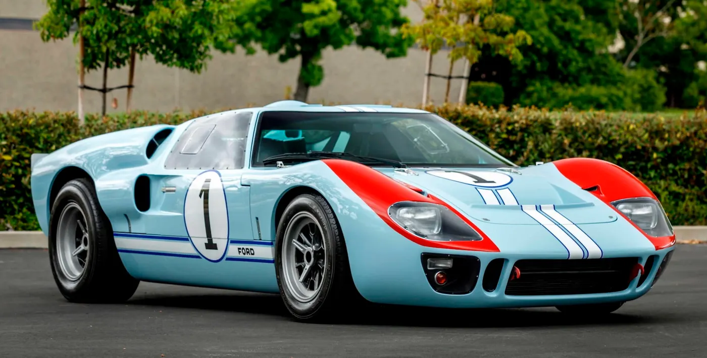
Figure 1: Original GT40 Mark-II
Basic Dimensions:
There were many variants of the high performance Ford GT40, but specifically Mark-II variant was chosen for modelling in this project. The Basic dimensions are given as follows:
Overall length = 4140 mm
Overall width = 1778 mm
Overall height = 1029 mm
Blueprint Setup:
The blueprint of the race car (figure 2) was downloaded from the website: the-blueprint.com. It was cropped accurately to pixels with the help of Adobe Photoshop. The foundation of the project was setting up of the blueprint correctly in the Solidworks environment.
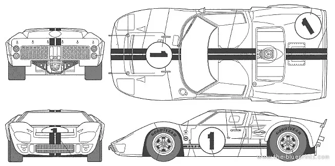
Figure 2: Blueprint
The Blueprint setup in the Solidworks:
Figure 3 shows the Front view, Back view, side view and top view, placed on the respective planes, separated by the distance as per the basic dimensions.
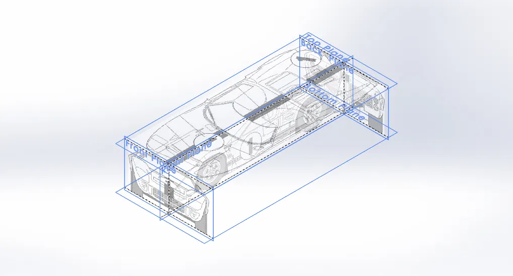
Figure 3: Blueprint Setup
Modelling the Body:
Surface Modelling:
Overview:
The next step was to create the all the outer surfaces of the left side of the race car with the help of surface modelling tools in Solidworks. The surfaces were later knitted together and converted into a solid.
Design Approach:
Features Used:
- 2D Sketch
- 3D Sketch
- Projected Curves
- Surface Lofts
- Surface Knits
- Surface Trim
- Surface Sweep
- Boundary Surface
- Ruled Surfaces
- Reference Planes
- Surface Fill
- Surface Extrude
Procedure:
- Reference Planes were created and 2D sketches were made in those planes.
- In case of lofted surface, which was predominantly used in this project, the 2D sketches were converted into a projected curve.
- The projected curves, 3D sketches and 2D sketches were used to create all the lofted surfaces
- In some instances, Sweep surface, Boundary surface and Fill surfaces were used to get the required desired surfacing.
- Trim surfaces were used to create complex surfaces on the side where, new surfaces had to be created as per the blueprint.
- All the surfaces were knitted together, and a solid was created. There were no problem with knitting; hence the surfaces weren’t modified in the later stages.
- Holes were made on the side were the tyres were to be mated.
Surface Modelling of the body (Figure 4) took about 80 % of the project time approximately.
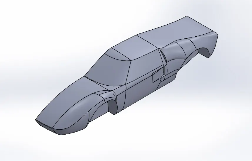
Figure 4 Surface Modelling of one side
Solid Modelling:
Overview:
Next the detailing on the body had to be done with solid modelling tools in Solidworks.
Design Approach:
Features Used:
- Cut Extrude
- Boss Extrude
- Dome
- Fillet
- Split Line
- Sweep
- Combine
- Revolve
- Mirror
Procedure:
- Cut extrude was used to create cuts for Radiator and Dome light housing.
- Boss extrudes and Dome was used to create the dome lights.
- Sweep was used to create the spoiler in the back.
- Cut Extrudes were used to create tail light housings and Exhaust manifold opening.
- Cut extrudes and boss extrudes were used to create the windshield, rear window, side windows in the race car.
- Mirror was used to create the other side of the car.
- Combine feature was used to combine all the parts together.
Figure 5 shows the model after mirroring and detailing.
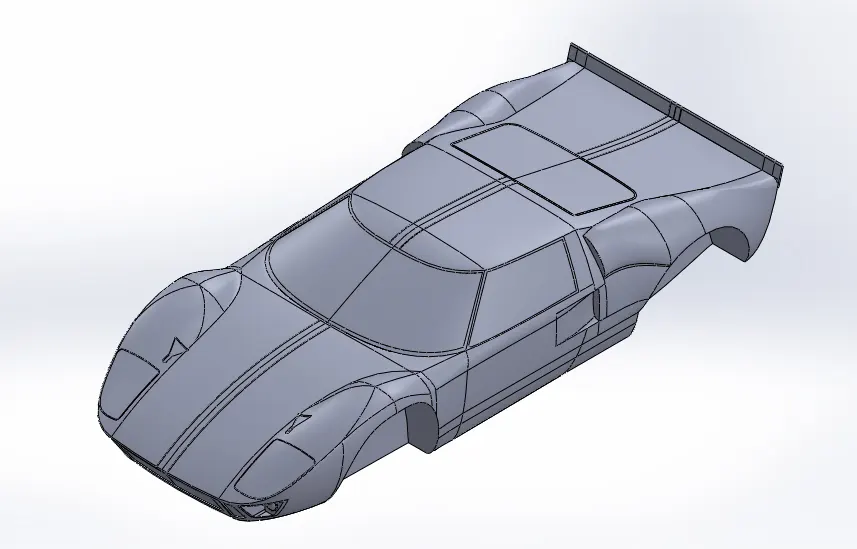
Figure 5: Mirrored part with detailing
Appearance:
Gulf Livery colour palette was chosen to colour the outer body of the race car.
The RGB combinations of the colours used are given below:
Gulf Blue : R106, G197, B244 – The Body
Burnt Orange : R252, G081, B011 – Headlight region
White : R255. G255, B255 – Headlight
Imdur White : R244, G244, B244 – Side stickers
Black1 :R064, G064, B064 – Windows, Radiator
Black2 :R000, G000, B000 – Bottom
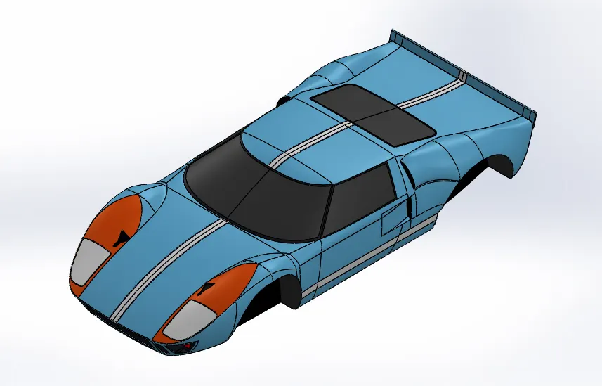
Figure 6: Appearance of the body
Modelling the Wheels:
Solid Modelling:
Overview:
The final Parts that were modelled were the front and back tyres and rims. The front and back wheels are similar in geometry and relations, but the only difference is its dimensions and size. Same design approach was done for both the tyres.
Design Approach:
Features used:
- Reference Planes
- 2D sketches
- Revolve
- Boss Extrude
- Cut extrude
- Fillets
- Circular Pattern
- Combine
- Dome
Procedure:
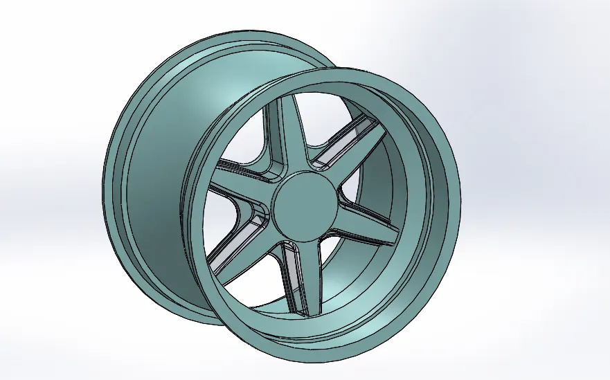
Rim:
- 2D sketch is created and revolved around to create the body of the rim.
- Boss Extrude is created for the Centre of the Rim.
- Boss extrudes, Cut extrudes and fillets were used to create the spoke, connecting the rim – centre and the rim body.
- Circular pattern feature was used to create six equally spaced spokes.
- Combine feature was used to merge the rim, spokes and rim – centre.
- Dome feature was used to create the centre cap
- Boss extrude was created which is an Axle lookalike, to be mated with the body.
Tyre:
- Intersection curve and splines were used to create the profile of the tyre.
- Revolve feature was used to create the Tyre Body.
- Cut extrude was used to create the single cut of the tread on the tyre.
- Circular pattern was used to create the continuous treads in the tyre with 40 equally spaced instances.
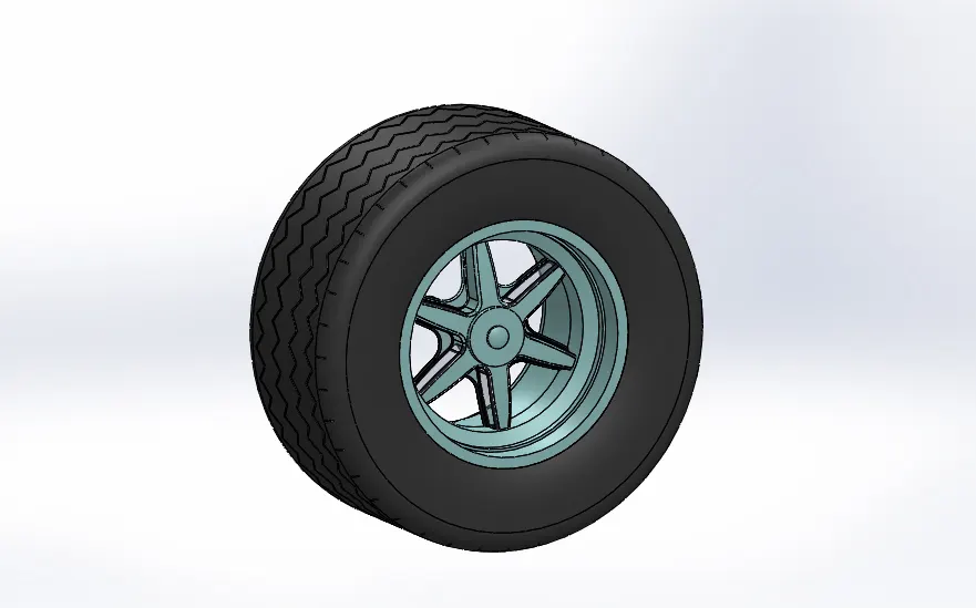
Figure 8: Final Wheel model
Appearance:
- Matte rubber was applied to the tyre.
- Chromium plate was applied to the rim.
Assembly:
The Body was brought in the assembly and fixed. The front and back tyres were imported and concentric and coincident mates were used to place the tyres in the appropriate positions as shown in Figure 9:
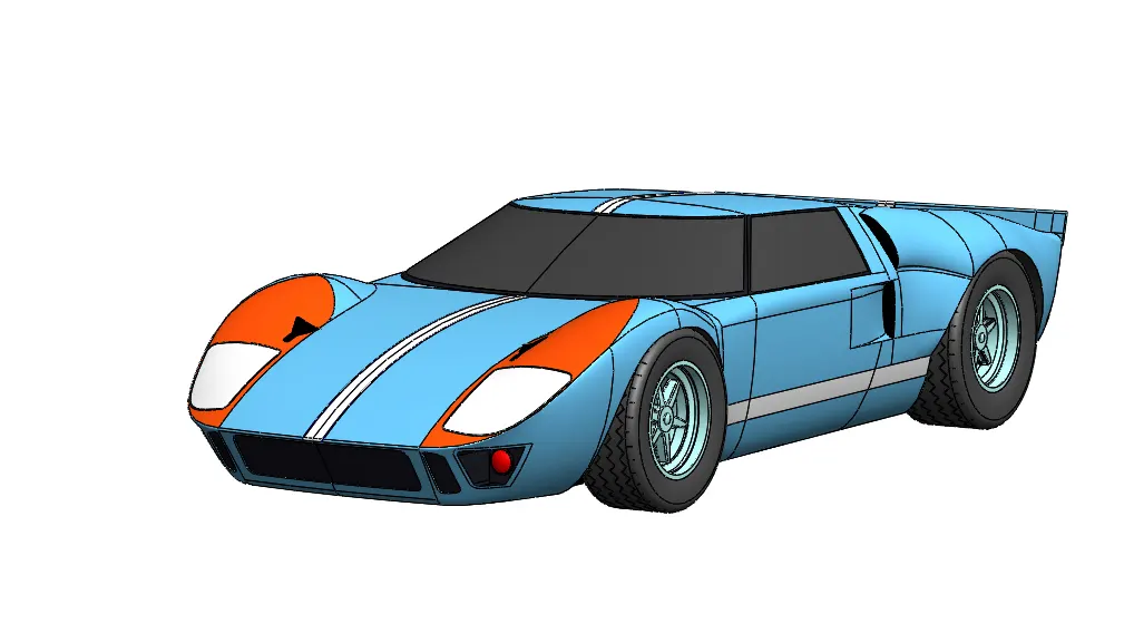
Figure 9: Assembly of GT40 in perspective view
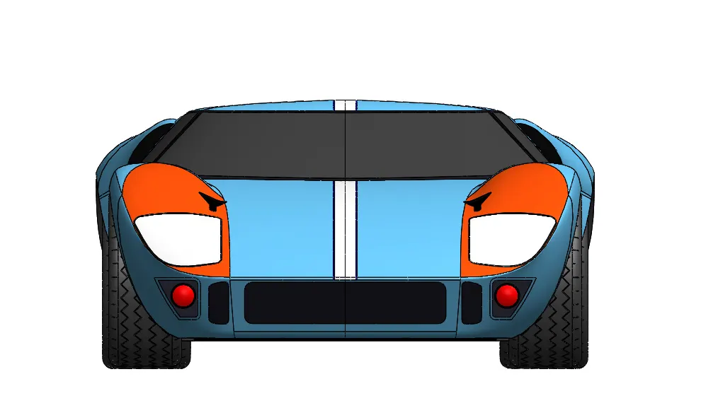
Figure 10: Front view
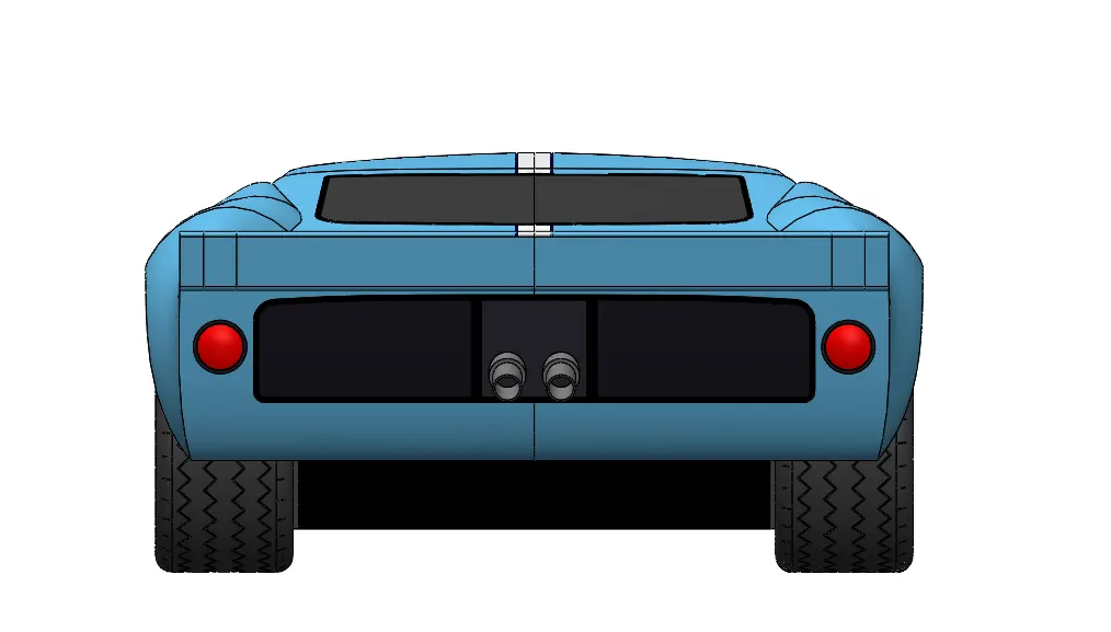
Figure 11: Back View
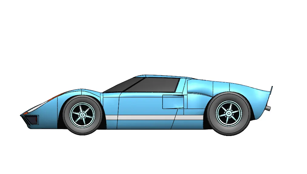
Figure 12: Side View
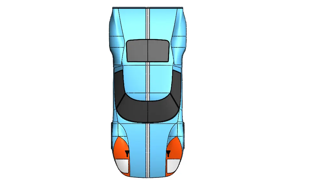
Figure 13: Top view
Rendering:
Rendering was done with the help of PhotoView 360 in Solidworks. Perspective view was enabled and camera was created to view the perspective.
- Scene was set to plain white
- Environment was set to urban05-bg_06
- Default lights were used.
The model is rendered with best quality. All the front, side, top and perspective views were rendered.
The images are attached below:
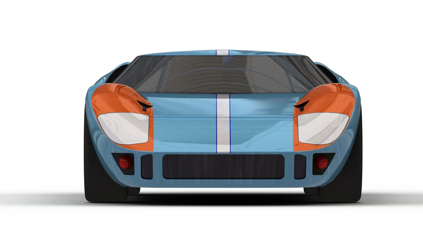
Figure 14: Rendered Front view
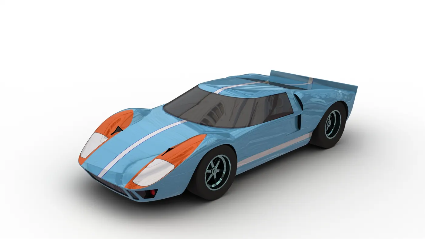
Figure 15: Rendered camera view
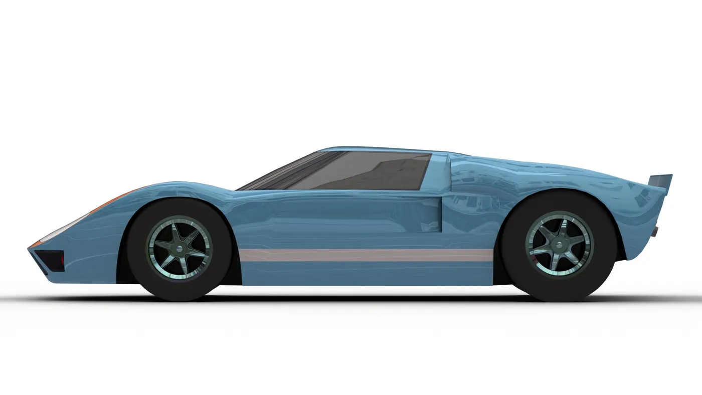
Figure 16: Rendered side view
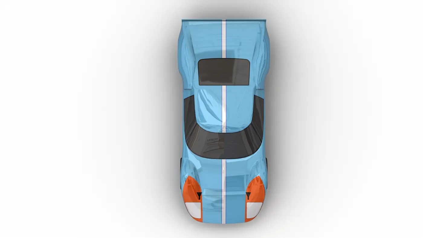
Figure 17: Rendered top view
Conclusion:
Thus the surface modelling of the body of the GT40, solid modelling of wheels and assembly were done with Solidworks. The surface modelling skills were heavily tested while creating this model. Rendering was also done with PhotoView 360 in Solidworks for high quality images.
Model:
Google Drive Link: Ford GT40
References: