Fender Design
1.0 AIM
Follow the given Master section to create the Drip Area.For the Sill, Bumper, Baffle(Splash), and A-Pillar mount create your own design according to the Engineering standard that you learned.Prepare a report with all the relevant images included for the mounting points created.
2.0 INTRODUCTION
2.1 FENDER
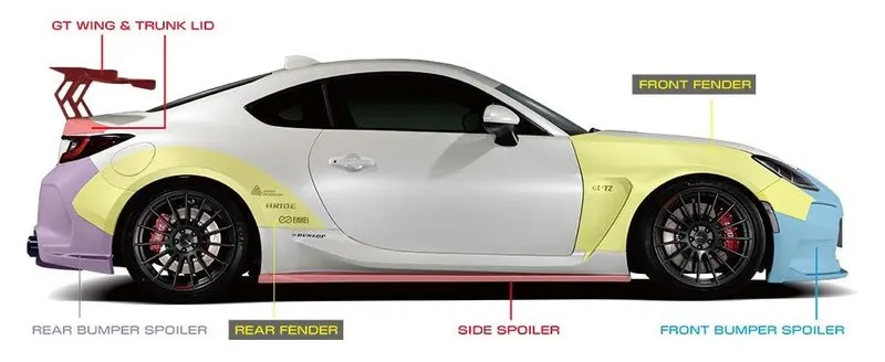
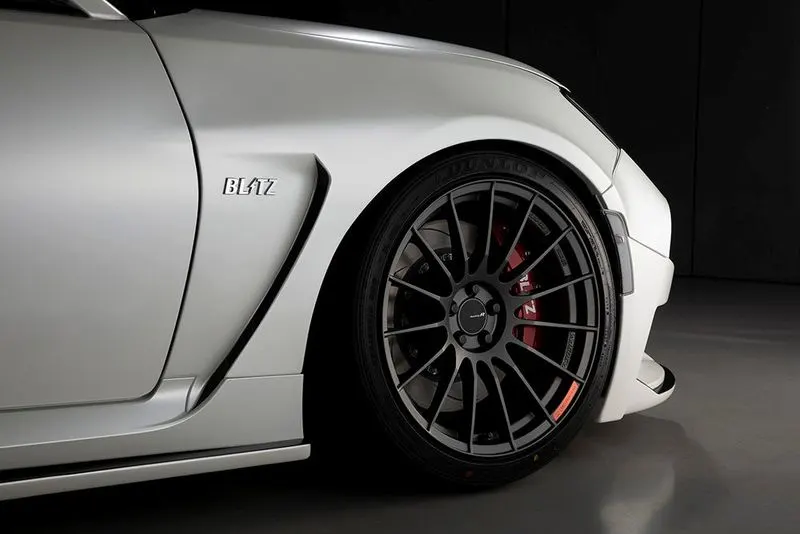
FIG.2.1 FENDER
A fender is the part of a car, truck, motorcycle, or other vehicles that frames or covers a wheel well. Its main purpose is to prevent debris, rocks, mud, liquids, sand, and other road debris from getting thrown in the air while the tire roate .The “fender” typically refers to the front panel that covers the front wheels, and the “quarter panel” typically refers to the rear panel that covers the wheel that also includes the roof pillar. The fender car part is the body kit or body part installed on the left and right sides of the vehicle. Manufacturers usually attach fenders to the wheel arches. There are different reasons why they are a requirement in vehicles. One obvious reason is to improve the aesthetics of the vehicle.Fenders also enhance the car’s aerodynamics. They also prevent mud, sand, rocks, liquid, and all sorts of debris from being thrown in the air while driving car.
To provide this kind of protection, fenders should have a firm and rigid material such as steel. If use every day on rough roads, it will experience a continuous “attack” of all kinds of debris.Mud and other sticky dirt can also adhere to the smooth rubber surface of the tires. Other loose debris, such as stones, can temporarily embed themselves in tire treads or grooves as the tire rotates while driving car.These foreign materials will be ejected from the tire surface and tread at high velocity as the tire imparts kinetic energy to them. While car is running, the tires rotate forward and upward.All passenger cars have broadly the same kind of fender. It’ll be made of the same material and color as the rest of the body and, as mentioned, blend as smoothly into the rest of the body as the design team can manage.The fender’s shape will roughly follow the curvature of the wheel sitting underneath it. It won’t run precisely parallel since cars often come with various wheel size options, but it’ll be pretty close.In every type of vehicle, each wheel has a separate fender liner. The function of fender liners is to prevent dirt, mud, water, environmental toxins, and other impurities from seeping into the engine bay causing serious damage.In addition, it also helps to protect the wires and other components inside the wheel well from corrosion. Driving a vehicle without a fender liner is not recommended as it acts as both a buffer and a barrier between car’s engine, hood, radiator, headlights, and windshield.
These are some of the reasons why car should have fenders. They catch the dirt, moisture, and debris and prevent them from hurting people and causing damage to other vehicles on the road. Fenders are there to contain these foreign materials within the confines of car.
3.0 MANUFACTURING PROCESS
Automobile panels are important parts of automobile, most of them are formed by sheet metal stamping, which has the characteristics of complex shape, large structure size, and high surface quality requirements. The fender is a covering panel that is installed on the left and right sides of an automobile body to cover the wheels. Because the forming quality of fender plays an important role in vehicle collision performance, the forming quality of fender is relatively high. Due to its deep drawing depth, complex shape, and other shape characteristics, it is relatively difficult to form. In the process of drawing forming, wrinkles, drawing breakage, springback, and other forming defects often occur.
3.1BENDING
Bending is one of the most common sheet metal fabrication operations. Also known as press braking, flanging, die bending, folding and edging, this method is used to deform a material to an angular shape.This is done through the application of force on a workpiece.V-bending is the most common bending method using a punch and die. It has three subgroups – bottoming, air bending and coining. Air bending and bottoming account for around 90% of all bending jobs.
- Bottoming is also known as bottom pressing or bottom striking. As the name “bottom pressing” suggests, the punch presses the metal sheet onto the surface of the die, so the die’s angle determines the final angle of the workpiece. With bottoming, the inner radius of the angled sheet depends on the die’s radius.
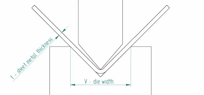
Fig.Bottoming
- Partial bending, or air bending, derives its name from the fact that the working piece does not actually touch the tooling parts entirely. In partial bending, the workpiece rests on 2 points and the punch pushes the bend. Is still usually done with a press brake but there is no actual need for a sided die.
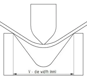
Fig. air bending
- The metal is given the die’s exact shape by applying great tonnage Coining derives it name from coins, as they have to be identical to make fake money distinguishable from the real one. Coining, in bending, gives similarly precise results. For instance, if you want to get a 45 degree angle, you need a punch and a die with the exact same angle. There is no springback to worry about.
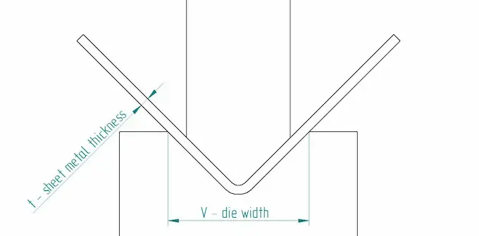
Fig.Coining
- U-bending is in principle very similar to V-bending. There is a die and a punch, this time they are both U-shaped, resulting in a similar bend. This is a very straightforward way for bending steel U-channels.
- step bending is, in essence, repetitive V-bending.Also called bump bending, this method uses many V-bends in succession to get a large radius for your workpiece. The final quality depends on the number of bends and the step between them. The more you have them, the smoother the outcome.
- Wipe bending, or edge bending, is another way to bend sheet metal edges. It is important to make sure that the sheet is properly pushed onto the wipe die. As a result, the wipe die also determines the bend’s inner radius. The slack between the wipe die and the punch plays an important role in getting a good result.o called bump bending, this method uses many V-bends in succession to get a large radius for your workpiece. The final quality depends on the number of bends and the step between them. The more you have them, the smoother the outcome.
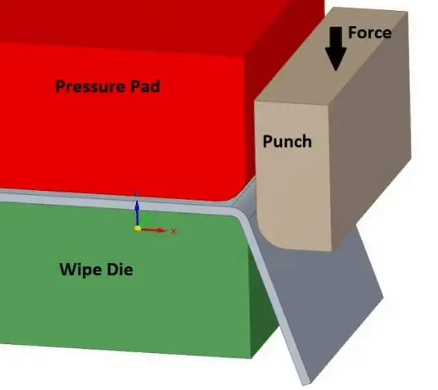
- Another way to bend edges is through rotary bending. It has a big advantage over wipe bending or V-bending – it does not scratch the material’s surface. Actually, there are special polymer tools available to avoid any kind of tool marking, let alone scratches. Rotary benders can also bend sharper corners than 90 degrees. This helps greatly with such common angles, as springback is not a problem any more.
- Bending Springback
When bending a workpiece, it will naturally spring back a little after the load is lifted. Therefore, it has to be compensated for when bending. The workpiece is bent beyond the required angle, so it takes the wanted shape after springback.
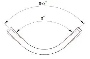
Fig.3.1 bending spring back
if the holes are too close to the bend, they may get deformed. Round holes are not as problematic as other types but your bolts may still not fit through. Again, see the bending force chart for minimum flange measurements and put the holes farther than the minimum.
4.0 FENDER DESIGN
FENDER MOUNTINGS
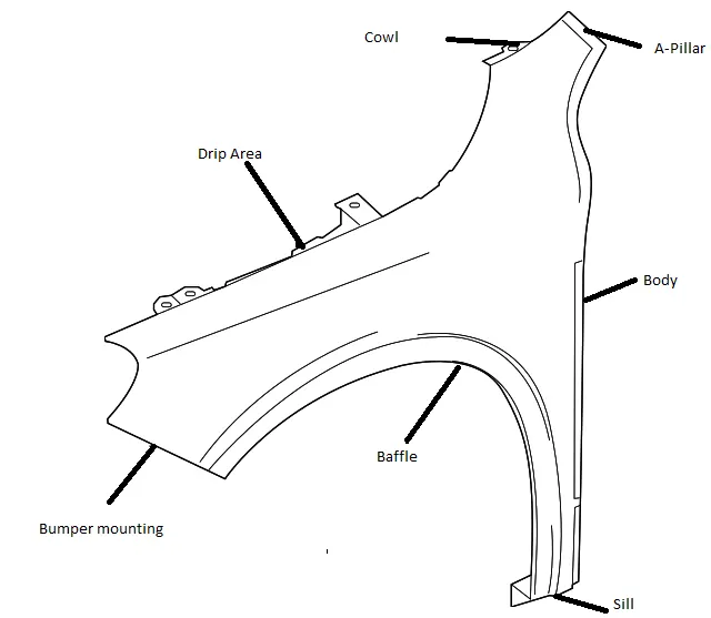
Fig . Fender mounting points
There are main five mounting points to fix the fender.
- DRIP
- BODY
- BUMPER
- SILL
- A-PILLAR
mainly fastners used to fix the fender.This regions hide by other car body parts.so it will not affect the aesthetics of the car.The master section for the design given below Fig 4.0
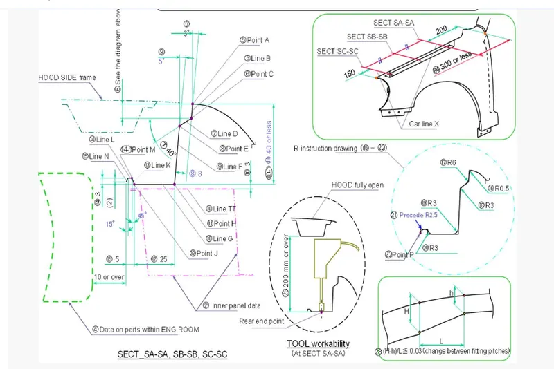
Fig 4.0 master section
- DRIP AREA
drip area is the region where the fender connected with engine compartment.drip area designed by following standerd design consideration.proper gap provided from the front and rear end of the fender for cowl and head lamp mountings.drip depth must be 40 mm for maximum productivity.if depth exceed it may cause wrinkling and spring back.based on master section accurate bend angle and clearence given for the drip area .
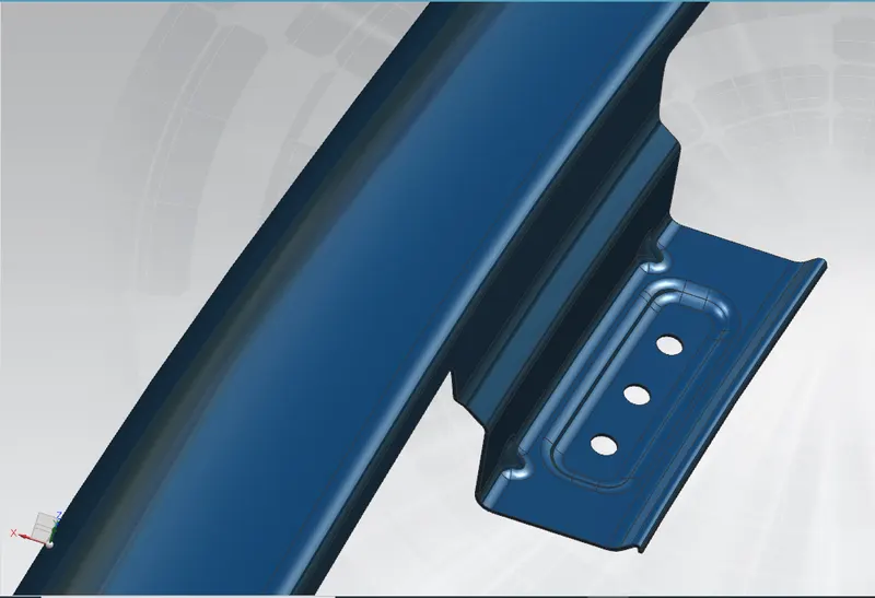
Fig.4.1 Drip Area
2. BUMPER MOUNTING
This region of the fender gets in contact with the front bumper of the car .proper area provided for fixing fastners and darts provide to stiffen the part.
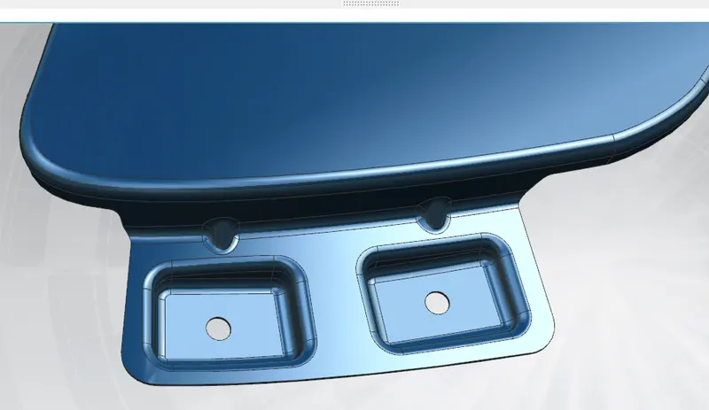
Fig 4.2 Bumper Mounting
3. SILL MOUNTING
This mounting region on the bottom side of the fender .Proper gap provided between the bend and hole for correct fiting of fastner.
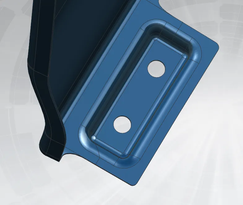
Fig 4.3. Sill mounting
4. A-PILLAR MOUNTING
The A-Pillar mounting joins the front fender to the A-Pillar, the vertically-angled pillar that supports the roof at the front side of the vehicle. The fender mounts with the A-Pillars to enhance the structural integrity of the vehicle in case of crash impact.
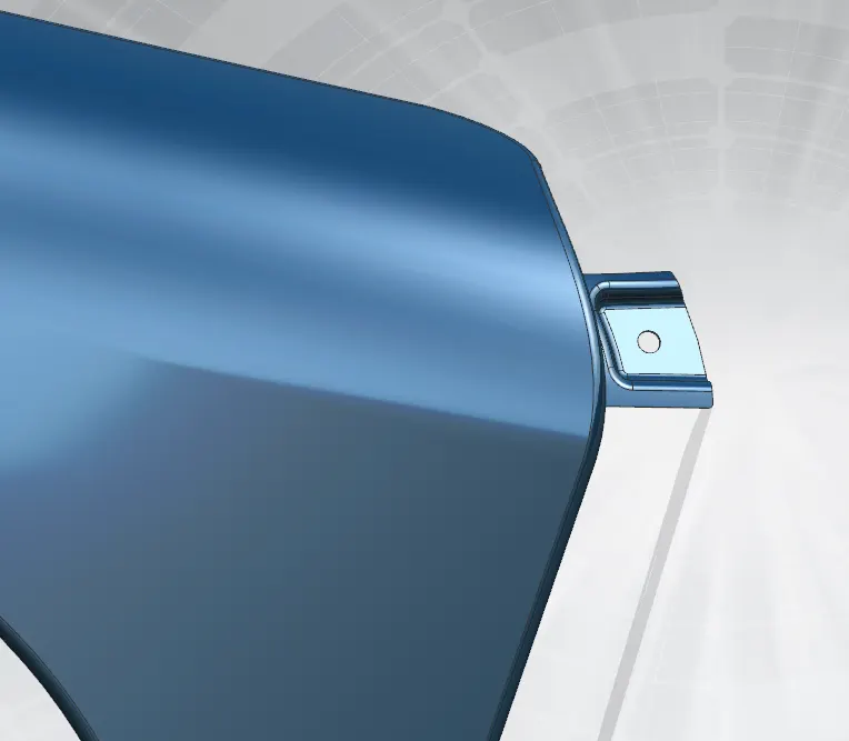
Fig 4.4 A-Pillar mounting
5. BAFFLE MOUNTING
This mounting is to fit a wheel arch area gor baffle. baffle is plastic unit used to fit for splash mounting .In this design holes provided for baffle mounting.
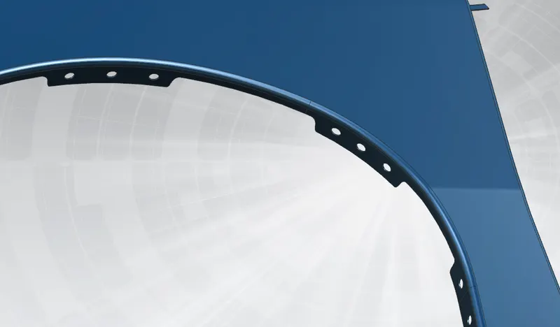
Fig 4.5 Baffle Mounting
5.0 CONCLUSION
Fender Drip Area,Sill, Bumper, Baffle(Splash), and A-Pillar mount area designed by flllowing the master section .