Challenge

Hood design-Week 2

                                                                                                                                DESIGN OF HOOD

The hood or bonnet is the hinged cover over the engine of motor vehicles. Hoods can open to allow access to the engine compartment, or trunk on rear-engine and some mid-engine vehicle for maintenance and repair.

                                                                                                   

                                                                                                                                Fig 1. Hood

Car hoods are typically constructed from steel and sometimes from Aluminium. Now many new types of materials like Carbon fibre, Fibre Glass and dry carbon are used in manufacturing of hoods.

HOOD DESIGN:

The important criteria for the design of the hood is the protection of the occupants inside the car during front collision. The design should be in such a way that during the collision the force should travel in the upward direction through the embosses and split to the sideways rather than travelling to the centre.
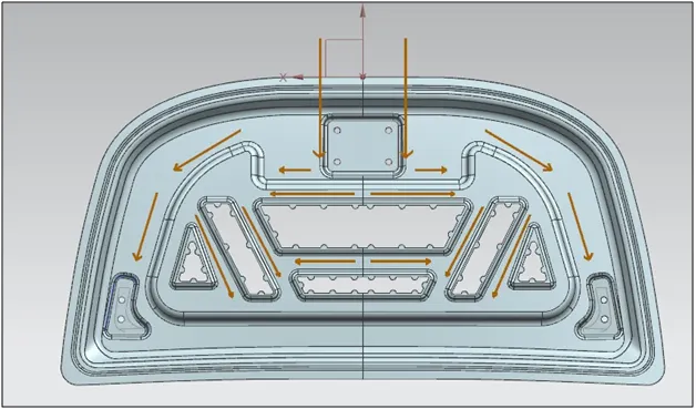
                                                                                 

                                                                                                                      Fig 2. Force direction during Collision

The hood consists of the following parts:

  1. The Outer Panel
  2. The Inner panel
  3. The Latch
  4. The Hinge

While Designing the Hood the main points to be considered are the following:

  1. The Latch Should be placed at the exact centre of the hood.
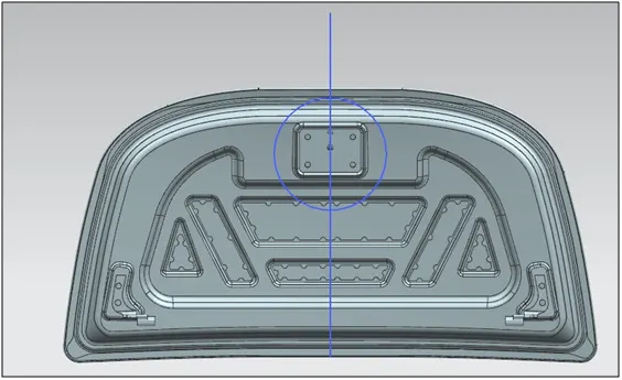
                                                                                    

                                                                                                          Fig 2. Latch Should be at exact centre of the hood.

  1. The Hinge axis should be in line with each other.
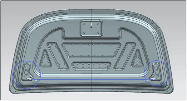
                                                                                  

                                                                                                                              Fig 3. Hinge axis in line.

  1. While hemming the outer panel with inner panel there should be no intersection between the parts.
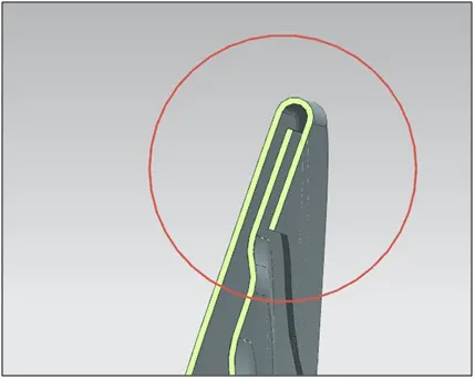
                                                                                                      

                                                                                                                                        Fig 4. Hemming

  1. The distance between the uppermost emboss on the inner panel and the outer panel should be 5cm for the placement of mastic seal to reduce the vibrations.
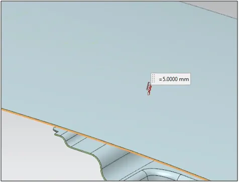
                                                                                                  

                                                                                                                                  Fig 5. Distance of 5mm

  1. The corner reliefs should be given for hemming process.
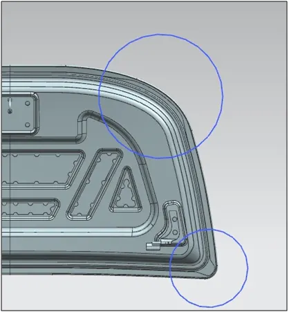
                                                                                                       

                                                                                                                                    Fig 6. Corner Relief

OUTER PANEL:

The outer panel is already available with us. It is the reference for outer panel.
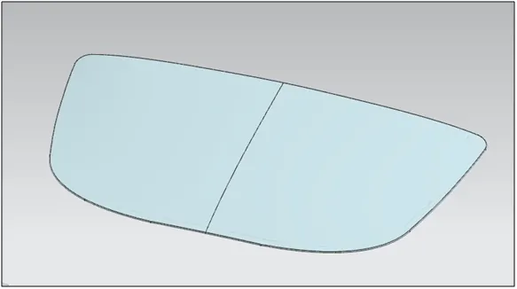
                                                                                     

                                                                                                                                  Fig 7. Outer panel

INNER PANEL:

The inner panel is created from the master section and taking the outer panel as reference.
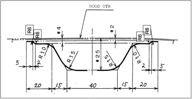
                                                                                   

                                                                                                                                      Fig 8. Master Section

The Features created in the designing of inner panel are:

Emboss:  Embossing is a stamping process for producing raised or sunken designs or relief in sheet metal. This process can be made by means of matched male and female roller dies, or by passing sheet or a strip of metal between rolls of the desired pattern.

Embossing can help disperse liquid more effectively, reduce friction and static, bolster metal panel stiffness and rigidity, increase metal surface area for acoustic or heat transfer and improve traction.
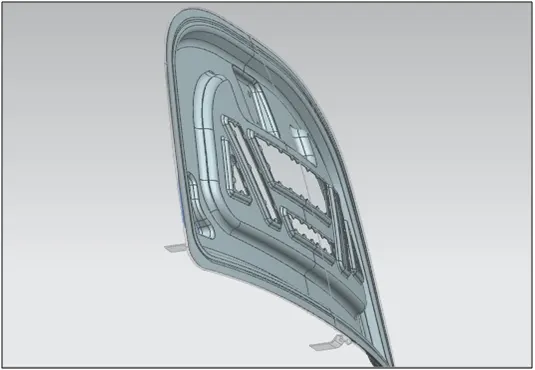
                                                                                             

                                                                                                                                        Fig 10. Emboss

Mastic Area: The mastic area is provided on the inner panel. It is the area where mastic sealant is applied to join the inner panel with the outer area. Mastic sealant is used to reduce the noise and vibrations.
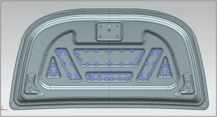
                                                                             

                                                                                                                                  Fig 11. Mastic sealant

Deep Drawing Simulation:

Deep drawing is a sheet metal forming process in which a sheet metal blank is radially drawn into a forming die by the mechanical action of a punch. It is thus a shape transformation process with material retention. The process is considered "deep" drawing when the depth of the drawn part exceeds its diameter.
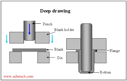
                                                                                     

                                                                                                                              Fig 12. Deep Drawing

In NX to check whether the sheet metal part we have designed can be deep drawn there is an option called draft analysis. This type of analysis is performed based on color ranges identifying zones on the analyzed element where the deviation from the draft direction at any point, corresponds to specified values.
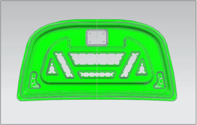
                                                                           

                                                                                                                             Fig 13. Draft analysis

Hemming:

At the corners the outer panel and the inner panel are joined together by hemming. No type of welding is done because it leaves a mark on the outer panel and damages the aesthetic beauty of the car.

Hemming is a forming operation in which the edges of the sheet are folded or folded over another part in order to achieve a tight fit. Normally hemming operations are used to connect parts together, to improve the appearance of a part and to reinforce part edges.

There are various types of hemming operations:

Conventional Die Hemming:  In conventional die hemming, the flange is folded over the entire length with a hemming tool.
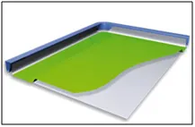
                                                                                                                         

                                                                                                                      Fig 14. Conventional Die Hemming

Roll Hemming: Roll hemming is carried out incrementally with a hemming roller. An industrial robot guides the hemming roller and forms the flange.
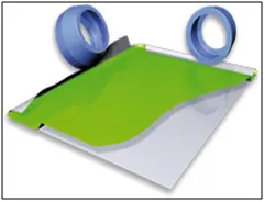
                                                                                                                         

                                                                                                                               Fig 15. Roller hemming
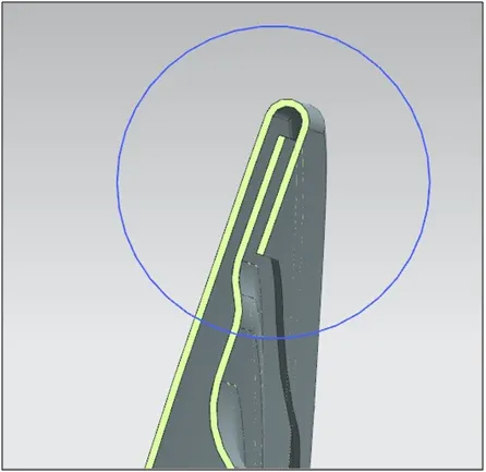
                                                                                               

                                                                                                                               Fig 16. Hemming

INNER PANEL VIEWS:
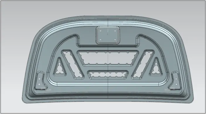
                                                                        

                                                                                                                                        Fig 17. View 1
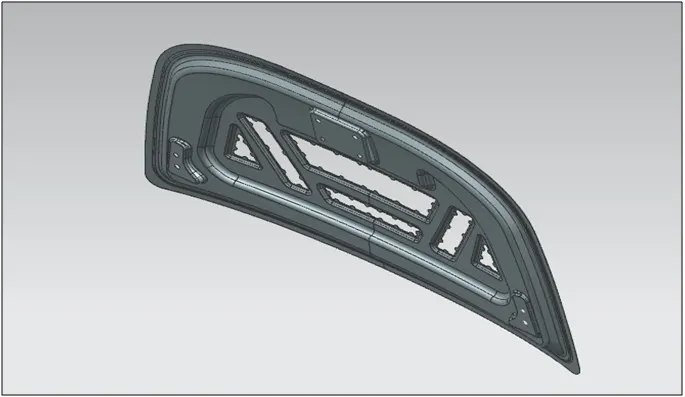
                                                                        

                                                                                                                               Fig 18. View 2

HINGE ASSEMBLY:

It consists of 2 parts. One which is attached to the inner hood and the other end to the engine compartment.
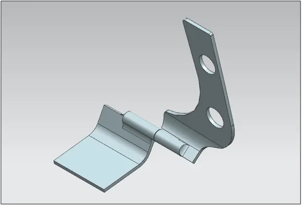
                                                                                   

                                                                                                                                        Fig 19. Hinge

LATCH:

Latch is that part which helps in closing the hood of the car. The placement of latch in the hood plays an important role. Latch should be at the exact centre of the hood.. For that some sketches should be drawn and constrained.

In the mid plane of the assembly draw a circle from the hinge centre point. Draw a line tangent to the circle and from the centre of the circle draw a line perpendicular to the tangent line.
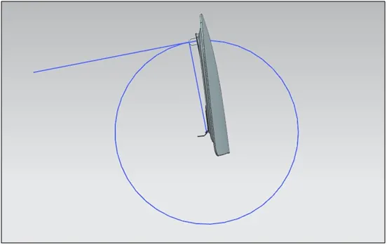
                                                                                       

                                                                                                                        Fig 20. Sketch for latch placement

In the same way draw a line at the centre of the latch and change the reference set to the entire part so that the sketch is visible in the assembly.
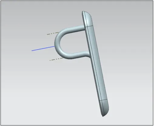
                                                                                              

                                                                                                                                Fig 21.Sketch in the latch

Now the centre line of the latch should be parallel to the tangent line and the centre point of the latch should be touching the intersection point of the tangent and the perpendicular line.

Assemble the hinge and mirror the assembly.

The Final Assembly Views:
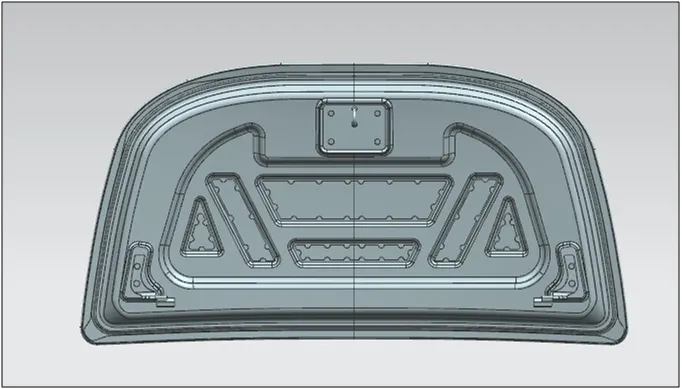
                                                                              

                                                                                                                                            Fig 22. View 1
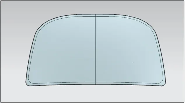
                                                                                 

                                                                                                                                         Fig 23.View 2
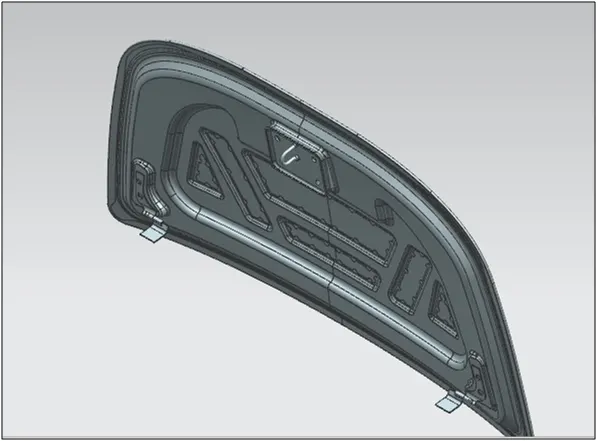
                                                                                   

                                                                                                                                 Fig 24. View 3

CONCLUSION:

The car hood was successfully designed in NX CAD.

Got a good understanding of all the design parameters to be considered in the designing of the hood.

                                                                                                                                              *************

Your portfolio, next

Ship work like this
in your own course.

Talk to a career counsellor

Free 20-minute call. We'll map the right course to where you want to work.

By submitting you agree to our Terms and Privacy Policy.

Talk to a career counsellor

Free 20-minute call. We'll map the right course to where you want to work.

By submitting you agree to our Terms and Privacy Policy.