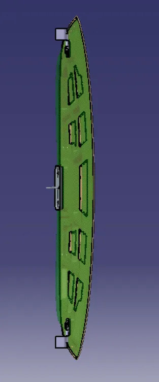
Hood design-Week 2
Introduction:-
Hood is a component of car used to cover the engine and its accessories, this hood design will gives the best and luxurious look for the car and some design considerations like weight and safety will be maintained while designing the hood.
Various considerations to be taken:
As hood is the primary and the most visible part of the car some considerations need to be taken throughout designing of hood.
- Manufacturing considerations:
The hood is made of sheet metal and the according to the manufacturing considerations
- Draft angle should be minimum 7 degree.
- Fillet radius should be a minimum of 3mm.
- Edges should be smooth.
- New Car assessment program(NCAP):
While designing hood the safety of passengers inside and the passengers outside the car should be taken care this is where NCAP comes in to action by performing various tests to provide rating for the vehicle based on the tests
- Embosses should be created in the manner that force should travel upwards through them.
- A minimum gap of 80mm should be maintained from the engine components to the inner panel of hood.
- No reinforcements should be provided in the impact zones, as the whole impact needs to be transferred to hood which will prevents severe injury.
- Noise, vibration and Harshness (NVH):
NVH deals with the noise and vibrations produced by the component and this should be taken in to consideration to reduce the noise and vibration produced by the component.
- Ergonomic and serviceability consideration:
Ergonomic and serviceability should be taken in to consideration for proper accessing of components
- Opening of hood
- Support of hood in open position.
- Position of striker and hinges which should not affect the engine components and proper locking of hood.
Design process:
Given data
Hood Thickness Information:
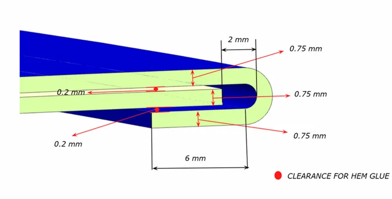
Outer Panel Thickness = 0.75mm
Inner Panel Thickness = 0.75mm
Reinforcement Thickness = 1.5mm
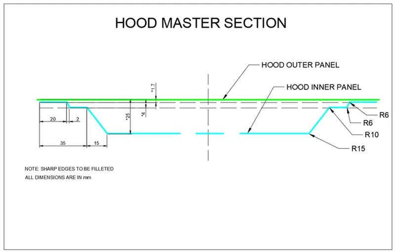
Master Section:
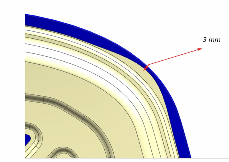
Hemming Data:
Relief rear section:
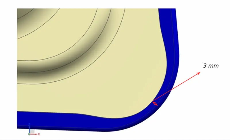
Front relief:
Based on the given data the hood assembly will be completed as mentioned in the below flow chart.
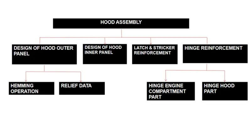
A top-down approach will be followed here as we were given a Class-A surface and master section was given.
Design of Inner panel:
Inner panel will be created by taking the master section as reference by following the considerations. The inner panel is having some steps which will be obtained by offsetting the surface.
Procedure followed
- Import the given class-A surface and name it as outer panel for reference
- Copy the surface and paste it in another part, so that we can use the surface for inner panel creation.
- Trim the surface to the half selecting the required plane as the surface has symmetry.
- Offset the trimmed surface to 1.7 mm downwards which will be our inner panel upper surface
- Create an parallel curve to the edge of the surface at an distance of 20 mm
- Trim the surface with curve which is created as parallel curve using split option
- Now again offset the main surface to 4 mm downward and create parallel curves to the edge at 22mm & 35 mm distance.
- Trim the surface using split command by selecting the parallel curve created and make sure the sure the surface between the two parallel curves will be remained.
- Join the surfaces by creating the shape fillet, which will create the fillet at the joined edges of the surfaces.
- Offset the main surface to the 25 mm downwards and create parallel curves to the edge of the surface at a distance of 50mm.
- Split the surface using the parallel curve created
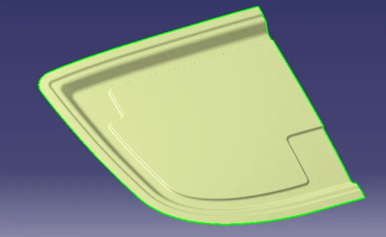
- The surfaces will be created as shown in the below image.
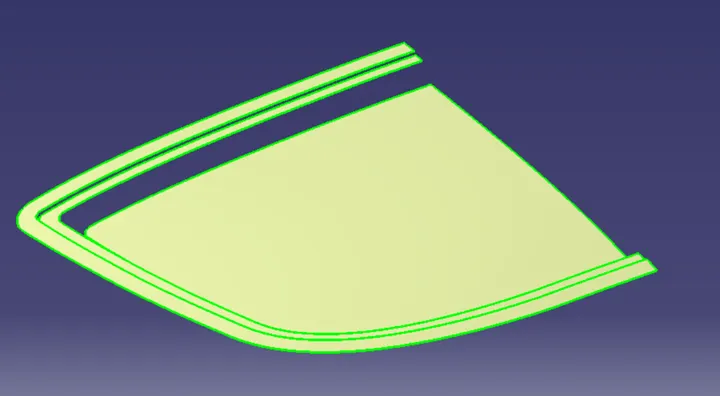
- Multi section surfaces are created using multi surface between the offset surfaces.
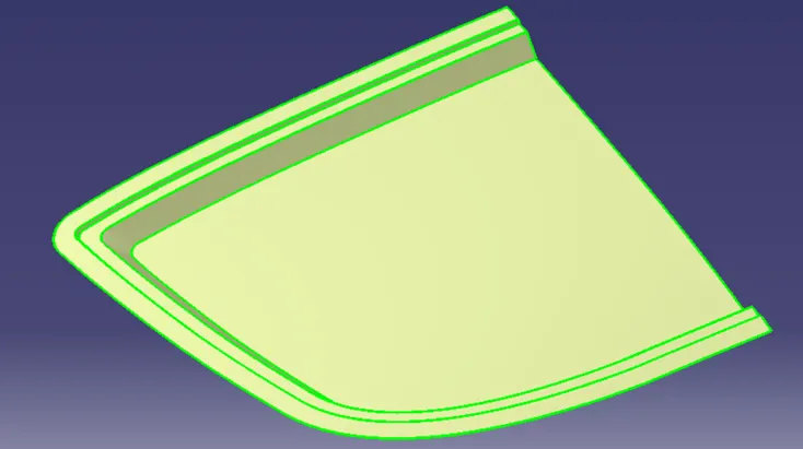
- Shape fillets are provided where the two surfaces need to be joined and the fillet should be provided.
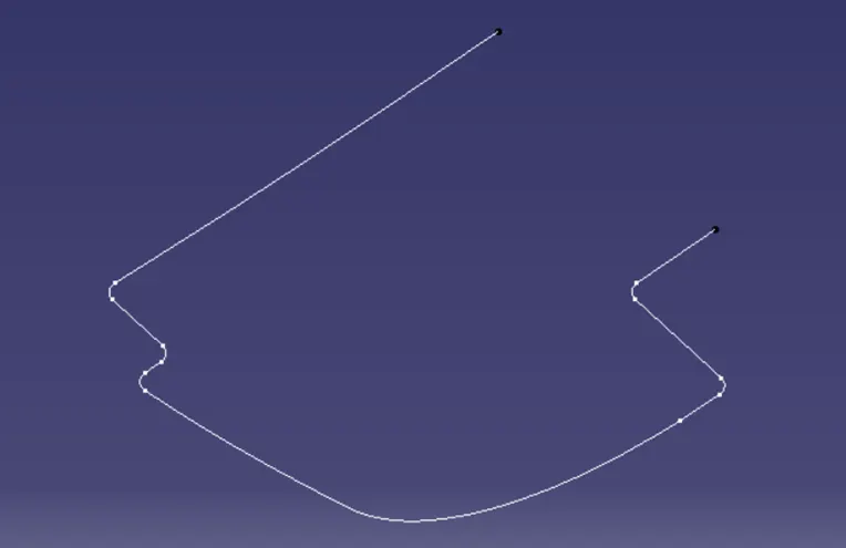
- Profile for embosses is created on the plane such that extrusion of the profiles will cut the surface created and enough space is provided for striker and hinge placement.
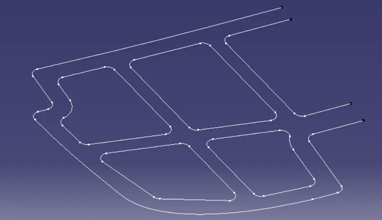
- Draw a sketch on the face and project it to the embossed surface which is created at an offset value of 5 to the downside surface and trimmed with main panel.
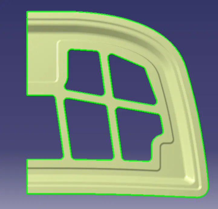
- The final surface will be created as
- Now as the hinge also follows the symmetry, hinge should be imported as a part and orientation should be made such that the hinge will be properly placed in the allocated area for creation of emboss.
Mastic data design:
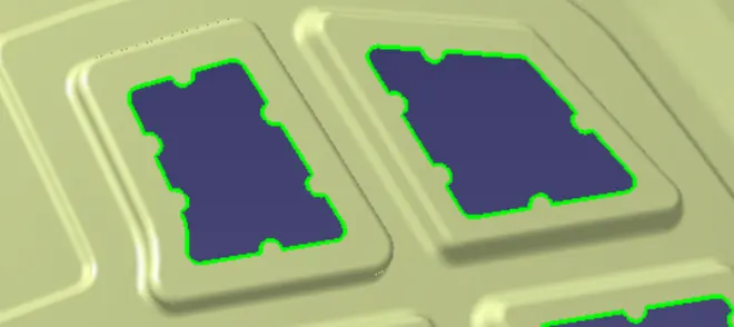
The main purpose of the outer panel is for the aesthetic looks, so we cannot use the welding to join the outer and inner panel. As the inner panel needs to be attached to the outer panel, at the edges hemming will be done but as the surface area is large it needs to be glued at the middle, there mastic seal will be applied.
- For mastic seal application proper surface need to be created for proper gluing a surface needs to be created at an offset distance such that gap between the outer panel and the offset surface should be 5mm.
Deep drawing:
Deep drawing is a sheet metal forming process in which a sheet metal blank is radially drawn into a forming die by the mechanical action of a punch. It is thus a shape transformation process with material retention.
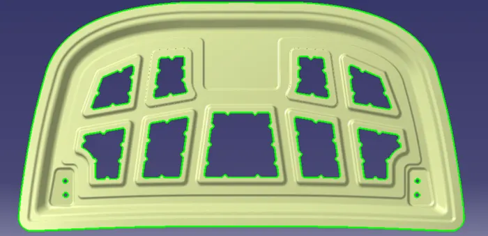
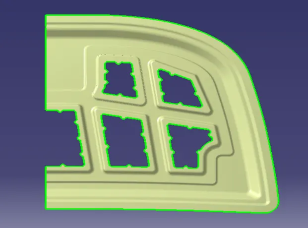
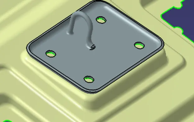
- Now the hinge and striker emboss need to be created, for that reference surface will be taken from the previously placed hinge and surface will be swept using the boundary of the reference surface and will be trimmed by the main input panel and fillets are provided.
- Symmetry for the surface will be created by selecting the proper trimmed surface and the plane at which the initial surface is trimmed.
- Now emboss for the striker need to be created but for striker there will be a particular path when closing the hood for that latch trajectory need to be created for proper alignment.
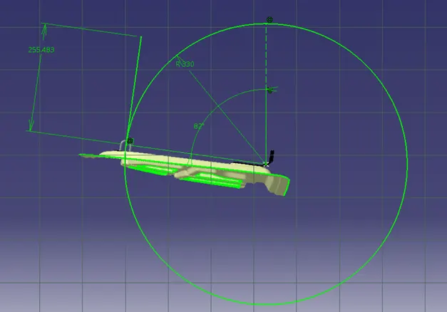
- After creation of trajectory the same process done in hinge emboss should be followed here for latch emboss creation.
- Now the complete inner panel is completed, the surface is thickened using thicken option with thickness as 0.75mm in the part design workbench to make it as a solid body.
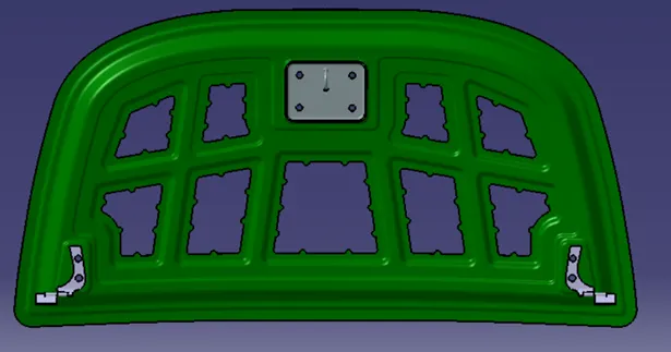
Designing of outer panel:
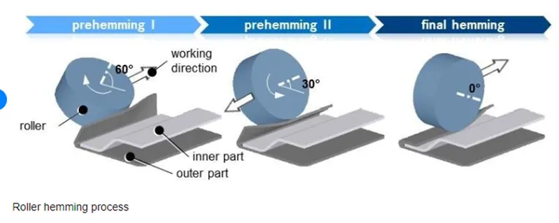
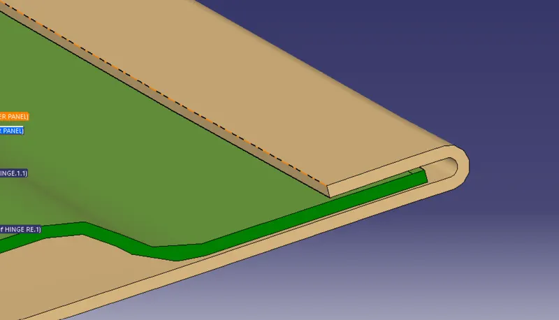
Hemming is a forming operation in which the edges of the sheet are folded over another part in order to achieve a tight fit.
The outer panel will be created using the given class-A surface, the surface needs to be modified as for the hemming process flange need to be created for the outer panel.
Procedure:
- Create an offset surface by selecting the outer panel surface for flange creation.
- Create an parallel curve taking edge of the offset surface and split the surface using the curve
Hemming relief
Hemming relief need to be provided as in hemming process one surface is folded over the other surface, In curvature surfaces due to folding at the corners surfaces will be overlapped to avoid this an relief will be provided by removing material at the corners.
- Hemming relief is provided to the offset split surface.
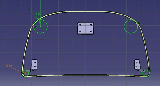
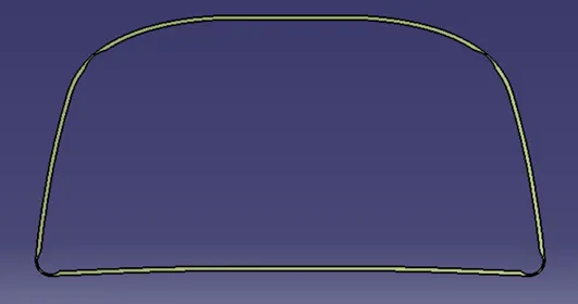
- After providing hemming relief the outer panel and the split surface with relief will be connected by creating multi-section surface.
- An tri-tangent fillet is used to create an fillet using the three surfaces selecting the upper and lower first and the side surface will be selected last based on the gap the fillet will be automatically formed.
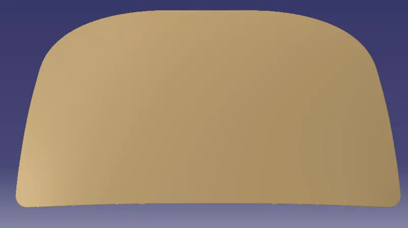
- The final outer surface is formed now.
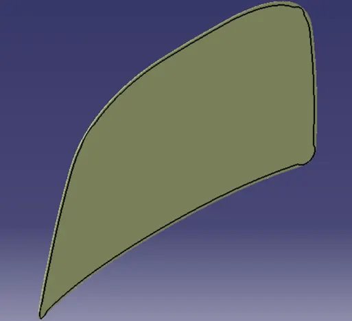
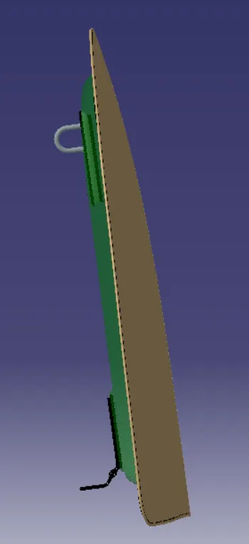
The inner and outer panel when assemble the sectional view will be as follows
Reinforcements:
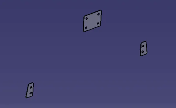
These are the support members, when fasteners are used on sheet metal shearing takes place to avoid these reinforcement plates will be created on the opposite side of hinge and latch emboss by taking the reference as their surface with a thickness of 1.5 mm.
Assembly:
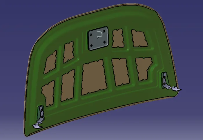
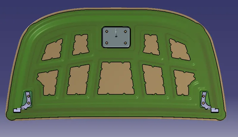
The final assembly of hood is created with outer panel, inner panel, hinge and its symmetry and latch and reinforcements of hinge and latch.