PART MODELLING, ASSEMBLY & RENDERING OF GO-KART IN SOLIDWORKS
PART MODELLING, ASSEMBLY & RENDERING OF GO-KART
Objective:
The main objective of this project is to create individual components of the Go-kart with proper dimensioning, constraints and with appropriate appearances based on the object type using Solid works modelling and making the whole a single assembly using different mates with all the parts and rendering it with a suitable scene using Solid works Photo 360.
Introduction:
Go-kart is a type of open wheel car, It is modelled based on our requirements and conditions It can be a normal or a racing kart based on the engines we provide, gear or gearless, high power or low power based on the end use of the product, it is mainly used for racings on long tracks and in this type of cars endurance is the main thing to be attained, so these type of cars will be mostly designed and fabricated keeping those conditions in hand. In this report we will be talking about the modelling of go-kart individual parts and appearances using solid works modelling, assembly of the go-kart and final rendering of the go-kart using scenes in Photo360.
Design Methodology:
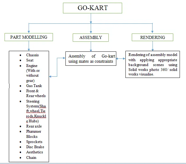
Tools & Features Used:
Individual parts of Go-kart are modelled using Solid Works part modelling each part is modelled using various features and tools based on their dimensions and method of approach.
The Tools & Features used are:
- Line: It is an entity used in sketching workbench to create a line of different types like for construction, centre line and midpoint line based on their applications.
- Circle: It is also an entity used and available in sketching workbench to create a circle of different types like circle and perimeter circle based on their applications.
- Spline: It is also an entity used and available in sketching workbench to create a spline of different types like spline, style spline and equation driven curve based on their applications.
- Rectangle: It is also an entity used and available in sketching workbench to create a rectangle of different types like corner rectangle, centre rectangle, 3 point corner rectangle, 3 point centre rectangle and parallelogram based on their applications.
- Arc: It is also an entity used and available in sketching workbench to create an arc of different types like centre point arc, tangent arc and 3 point arc based on their applications.
- Ellipse: It is also an entity used and available in sketching workbench to create an ellipse of different types like ellipse, partial ellipse, parabola and conic based on their applications.
- Slot: It is also an entity used and available in sketching workbench to create a slot of different types like straight slot, centre point straight slot, 3 point arc slot and centre point arc slot based on their applications.
- Polygon: It is also an entity used and available in sketching workbench to create a polygon and can change the number of sides based on their applications.
- Sketch fillet: It is also an entity used and available in sketching workbench to create a fillet or chamfer based on their applications.
- Point: It is also an entity used and available in sketching workbench to create point.
- Trim entities: It is a tool available in sketching workbench used to trim entities or extend entities based on the application the particular tool is used.
- Convert entities: It is a tool available in sketching workbench to project the sketch selected on the plane you are sketching and in this tool another option of intersection curve is there which is also used to project sketch.
- Offset entities: It is a tool available in sketching workbench to create an offset of sketch at a certain distance based on their applications.
- Mirror entities: It is a tool available in sketching workbench to create a mirror of sketch with respect to the axis selected based on their applications.
- Pattern: It is a tool available in sketching workbench in this tool two options are available linear sketch pattern and circular sketch pattern to create patterns of sketch based on their applications.
- Dynamic Mirror entities: It is a tool available in sketching workbench to create mirror of the sketch while drawing the sketch it is similar to mirror entities.
- Sketch Dimensions: It is a tool available in sketching workbench to create dimensions for the sketches to make constraint.
3D-Features are:
- Extrude Boss/Base: It is available in features tab used to add material to a closed sketch in which direction we want based on applications.
- Revolved Bass/Base: It is available in features tab used to add material to a closed sketch in revolving manner to which direction we want based on applications.
- Swept Boss/Base: It is available in features tab used to add material to a closed sketches along the guide curve based on applications.
- Lofted Boss/Base: It is available in features tab used to add material to a closed sketches of different sketches on different planes along the guide curve based on applications.
- Extrude Cut: It is available in features tab used to remove material from a solid body along the sketch in which direction we need based on applications.
- Revolved Cut: It is available in features tab used to add material by revolving along particular axis along sketch in which direction we need based on applications.
- Swept Cut: It is available in features tab used to add material to a closed sketch along the guide curve based on applications.
- Fillet: It is available in features tab used to make fillet or chamfer to edges of solid bodies.
- Linear Pattern: It is available in features tab used to pattern bodies, features, faces in linear or circular direction based on a single point and the direction we need based on applications.
- Draft: It is available in features tab used to create tapered surface by which angle you need and from which surface you need based on applications.
- Shell: It is available in features tab used to give wall thickness by removing all the inner material of a solid body except the given thickness based on applications.
- Mirror: It is available in features tab used to mirror the bodies or features with respect to plane based on applications.
- Reference Geometry: It is available in features tab used to create reference plane, axis, co-ordinate system or point based on applications.
- Curves: It is available in features tab used to project curves based on two curves on different planes and the composite curve which is used to combine the projected curves to make a single composite curve.
- Dome: It is available in features tab used to create closed surface in the form of circular or ellipse on an edge surface.
- Split: It is available in features tab used to split the body in two pieces along the sketch based on applications.
Surface Features used are:
- Extrude Surface: It is available in surfaces tab used to add material to a sketch with surface thickness in which direction we want based on applications.
- Swept Surface: It is available in surfaces tab used to add material to an open or closed profile with surface thickness along the path based on applications.
- Lofted Surface: It is available in surfaces tab used to add material to a different profiles with surface thickness along the guide curve based on applications
- Boundary Surface: It is available in surfaces tab used to create boundary surface between two profiles in two directions.
- Filled Surface: It is available in surfaces tab used to construct a surface patch within a boundary defined by existing model edges, sketches or curves.
- Fillet: It is available in surfaces tab used to create a rounded internal or external face along the edges on surface.
- Trim Surface: It is available in surfaces tab used to trim surface where on surface intersects with another surface, plane or sketch.
- Knit Surface: It is available in surfaces tab used to combine two or more adjacent and non-intersecting surfaces together.
- Ruled Surface: It is available in surfaces tab used to insert ruled surfaces from edges.
- Offset Surface: It is available in surfaces tab used to create offset surface using one or more continuous faces.
- Delete Face: It is available in surfaces tab used to delete faces from solid bodies to create surface or delete faces from surface bodies.
- Thicken: It is available in surfaces tab used to create a solid feature by thickening one or more adjacent surfaces
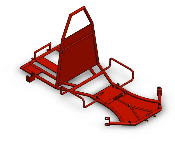
- CHASSIS:
The chassis of go-kart is a skeleton frame made up of pipes and other materials of different cross sections. The chassis of go-kart must be stable with high torsional rigidity, as well as it should have relatively high degree of flexibility as there is no suspension.
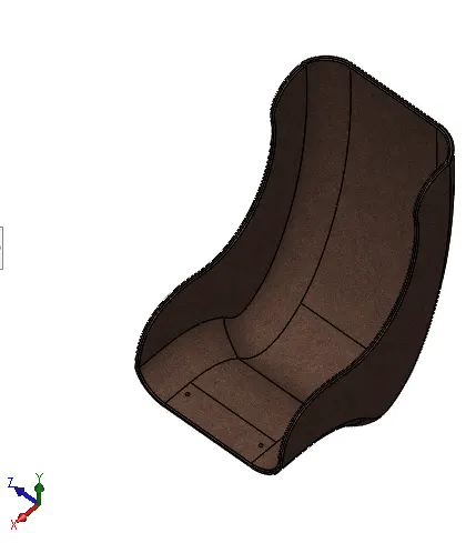
SEAT:
Seats are the objects which are used to take rest or to have a stable position, in racing karts there will be only single position which will ensure to maintain all possibilities of operations.
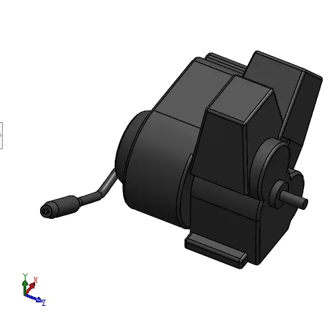
ENGINE:
karts are usually powered by a four-stroke gasoline engine producing anywhere from 5 to 13 hp (4 to 10 kW), or sometimes by an electric motor.
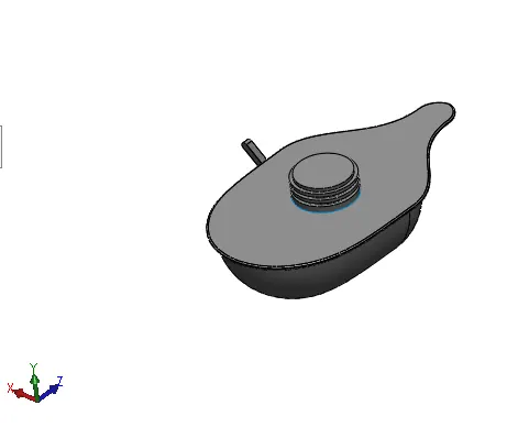
GAS TANK:
It is a fuel storing device and it will be connected to engine by means of a tube and the capacity of the tank will depends upon the engine and the racing condition.
FRONT & REAR WHEELS:
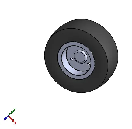
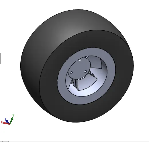
Go kart wheels are usually made of either aluminium, wheels are a good all-round choice balancing price and performance, there will be two types of wheels available dry tyres and wet tyres.
STEERING SYSTEM(SHAFT,WHEEL,TIE RODS):
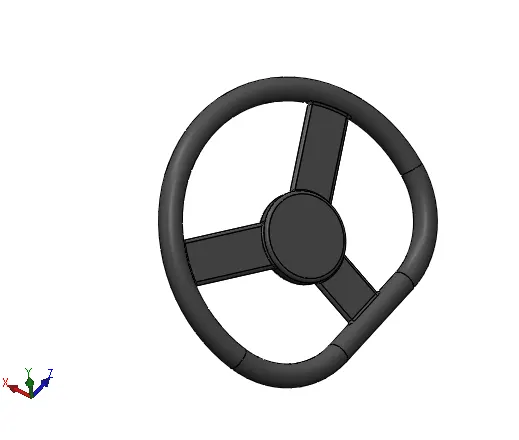
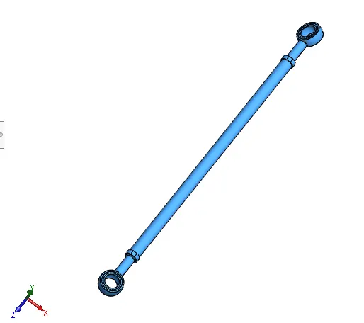
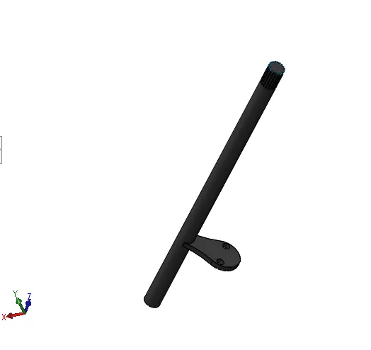
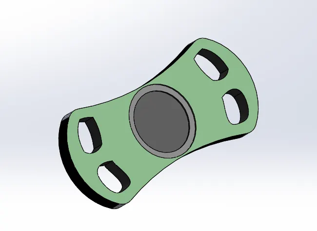
The ackermann steering system or the steering knuckles system is where the axles are mounted on knuckles out and away from the go kart. The wheels rotate vertically around these pivots, and cause the wheels to turn. There is a relationship in the wheels movement to a turned centre. It will includes steering shaft, steering wheel, tie rods.
KNUCKLE HUBS:
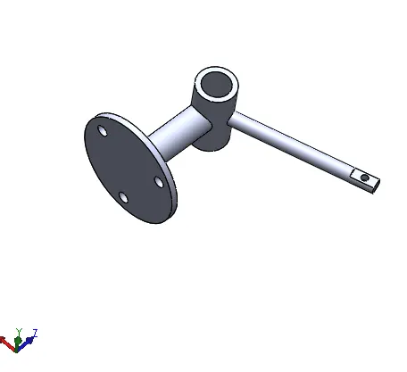
The wheels rotate vertically around these pivots, and cause the wheels to turn these are connected to chassis these will act as a connection between wheels and steering system.
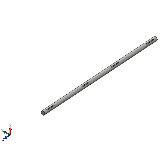
REAR AXLE:
In Go-kart this axle is responsible for delivering power to the driving wheels. It will be connected to engine with chain sprockets and will be fitted to chassis using plummer blocks.
PLUMMER BLOCKS:
Plummer block is a pedestal used to provide support for a rotating shaft with the help of compatible bearings & various accessories.
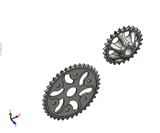
SPROCKETS: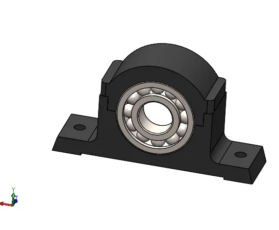
Sprocket-wheel is a profiled wheel with teeth, or cogs, that mesh with a chain. The name 'sprocket' applies generally to any wheel upon which radial projections engage a chain passing over it.
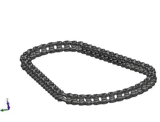
CHAIN:
Chain drives are widely used for the transmission of power where shafts are separated at distances greater than that for which gears are practical. In such cases, sprockets take the place of gears.
DISC BRAKE:
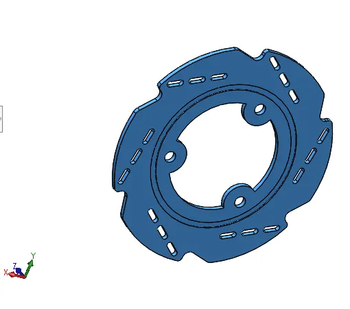
It is a device which is mounted on rear axle to stop the torqur of the shaft provided by engine by applying brakes.
AESTHETICS:
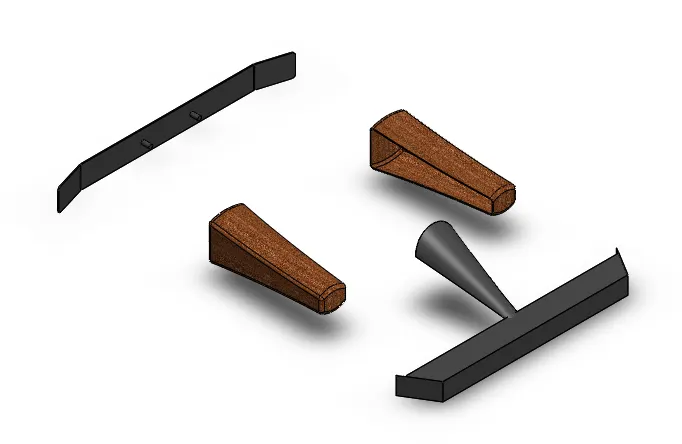
Aesthetics are the components which will give good looking while they are attached and will provide as safety in go-karts
ASSEMBLY:
Assembly means joining all the individual components of a model using mates as constraints which will give motions or will be stationary with respect to another part. This will result in the complete model which we want to obtain.
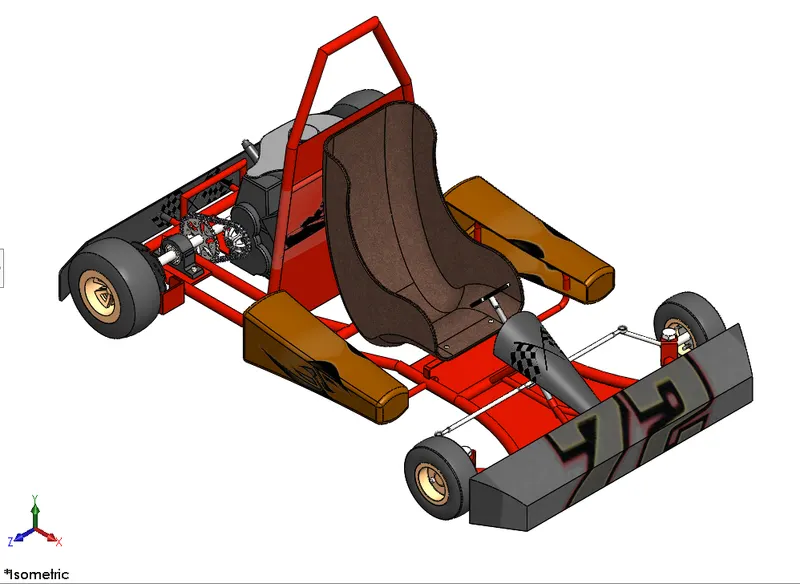
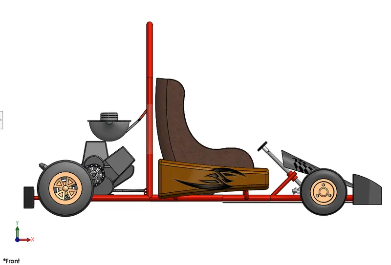
In Go-kart Modelling all the parts are modelled individually and appearances are applied to each parts based on their material and each part is opened in assembly workbench and are joined using mates (Coincide, Distance, Parallel, Concentric, Angle, Width, Limit Angle, Tangent) and one of the part of the whole assembly is made to be fixed to make the whole assembly perfect that means all other parts are joined to that fixed component using mates. So if the Assembly is moved all the parts will also move with respect to the component which is made fixed
The Images of Go-kart Assembly are:
ISO-METRIC VIEW OF ASSEMBLY
FRONT VIEW OF ASSEMBLY
RIGHT SIDE VIEW OF ASSEMBLY
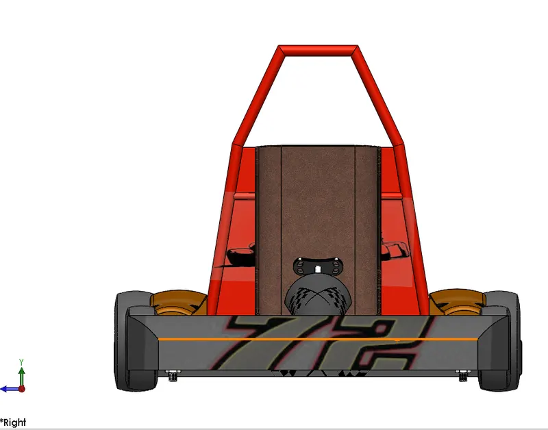
TOP VIEW OF ASSEMBLY
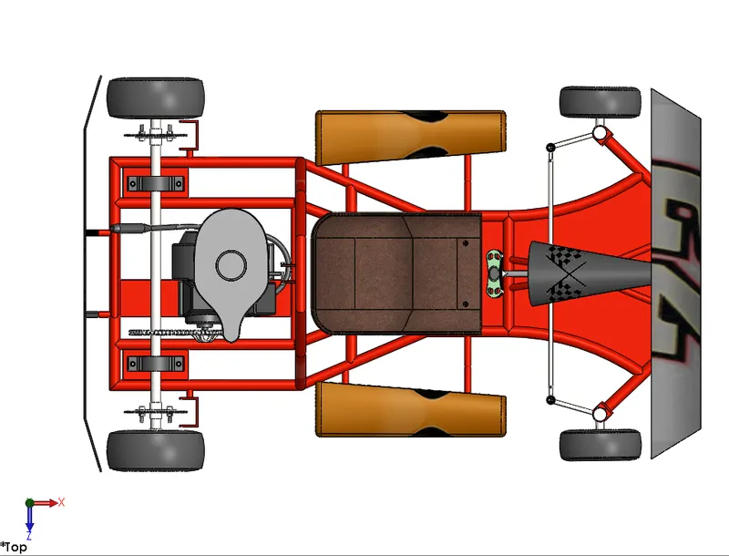
BOTTOM SIDE VIEW OF ASSEMBLY
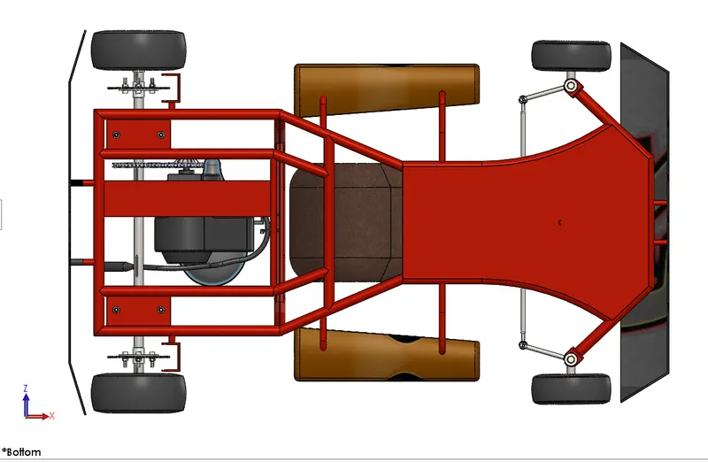
CAMERA VIEW OF ASSEMBLY
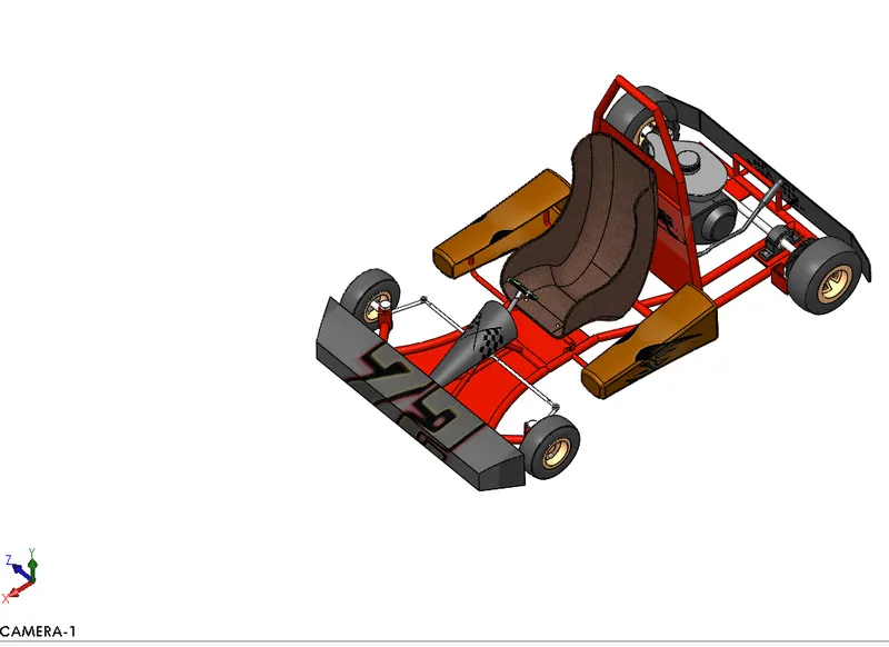
RENDERING:
In solid works we have Photo360 and Solid works Visualise to render any model, to make a model realistic as it looks in the outer environment, we can setup lights cameras in the way we want to look the model better and we can add decals to the parts which will give a good looking of the model we can customize the model by creating background scenes which will add environment to the model.
Rendering OF assembly model without using lights, background scenes.
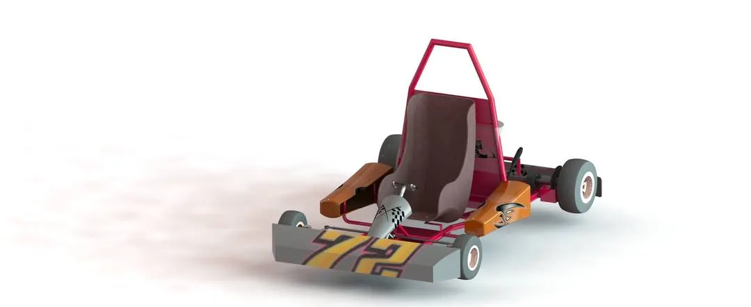
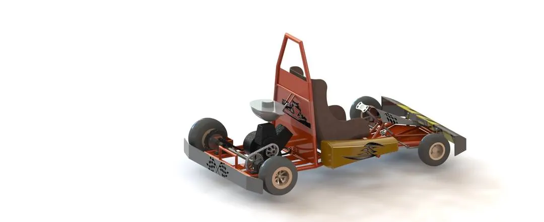
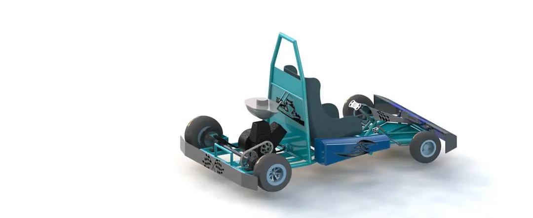
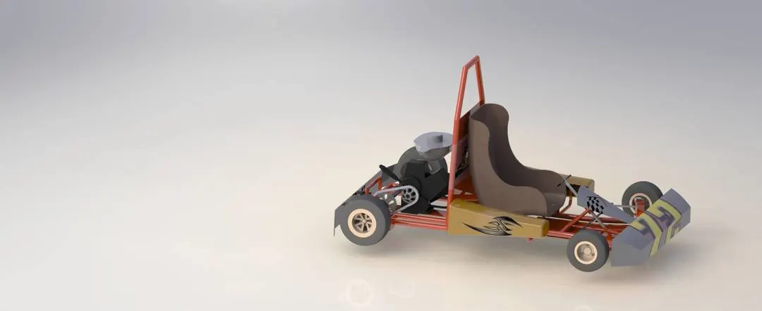
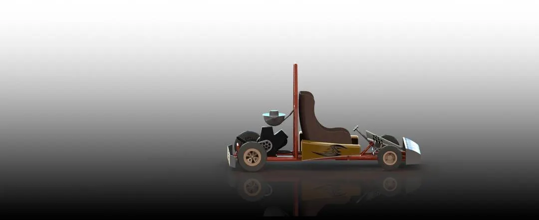
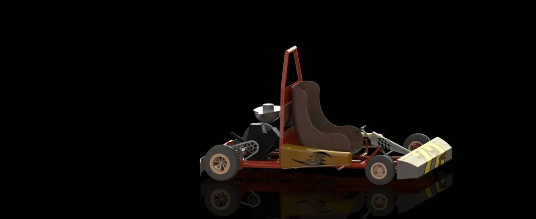
By using Photo 360 Final rendering appropriate background scenes option we can get the renders of model as shown below.
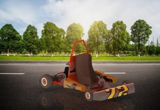
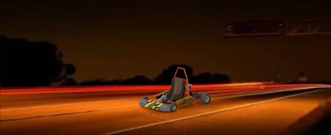
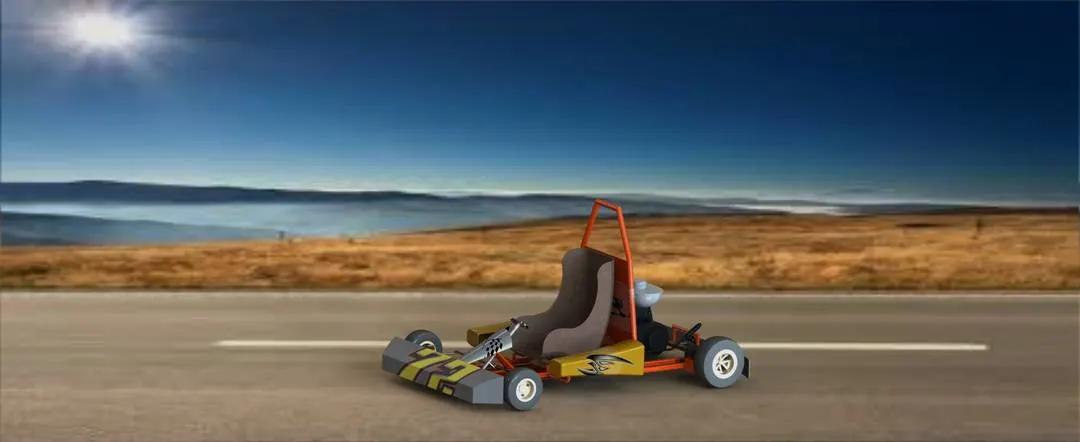
By observing the above images we can find the difference that after setting the background scene as nice environment was added to the model which is very good looking
CONCLUSION:
In this go-kart parts modelling, assembly and rendering. I had modelled individual parts and added appropriate appearances in solid works part modelling workbench and assembled all the parts using mates in solid works assembly modelling and for the better looks added decals, created camera views and rendered using appropriate scenes to the final assembly model using Solid works Photo 360.