AMERICAN CHOPPER PART MODELLING, ASSEMBLY & RENDERING
AMERICAN CHOPPER PART MODELLING, ASSEMBLY & RENDERING
Objective:
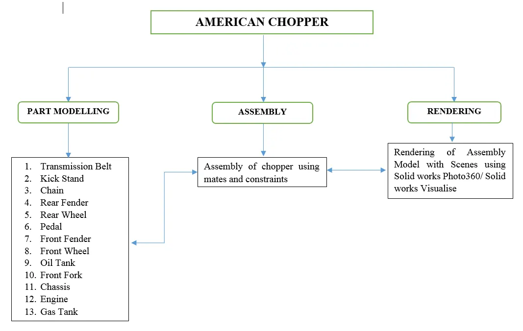
The main objective of this project is to create individual components of the chopper with proper constraints with appropriate appearances using Solid works modelling and making it a single assembly using all the parts and rendering it with a suitable scene using Solid works Photo 360.
Introduction:
American Chopper is a custom designed model based on our own requirements, its basic features are extended front fork and seat is located very near from the base and rear wheel and the engine in this model is dual cylinder engine with dual exhaust. In this report we will be talking about the modelling of chopper individual parts and appearances using Solid works modelling, assembly of the chopper and final rendering of the chopper using Photo360.
Design Methodology:
Tools & Features Used:
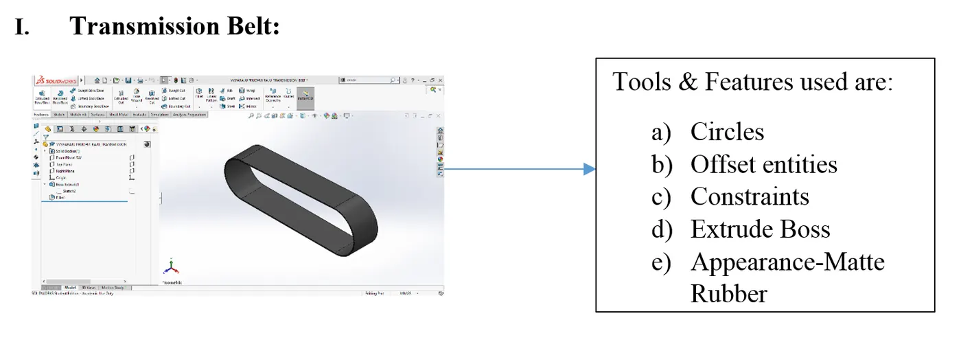
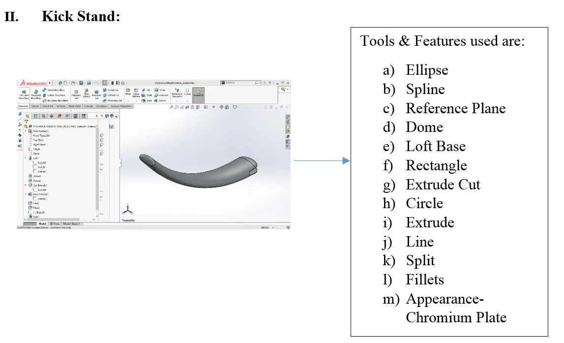
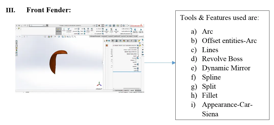
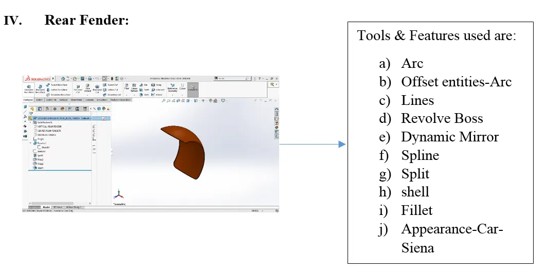
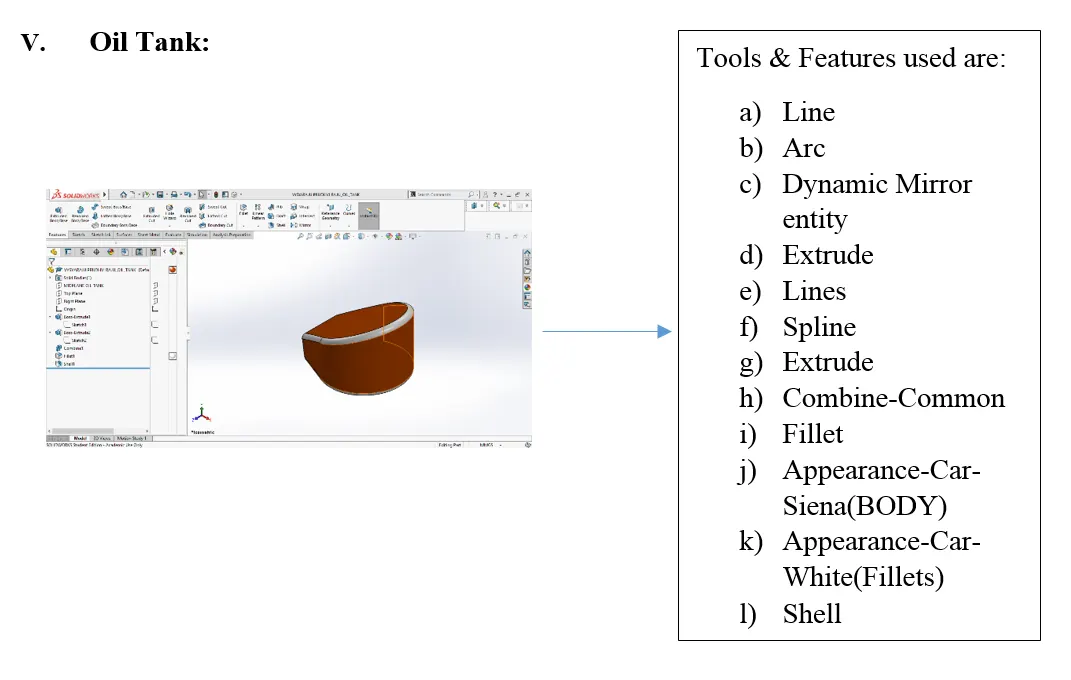
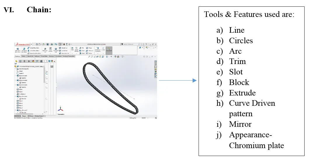
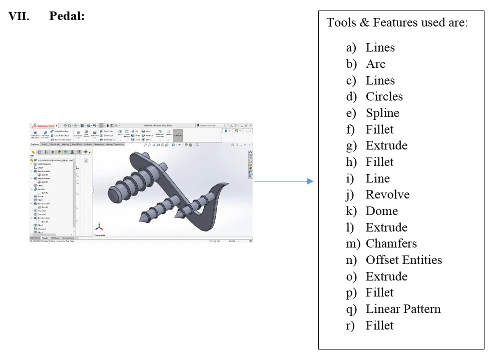
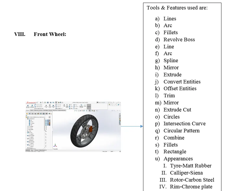
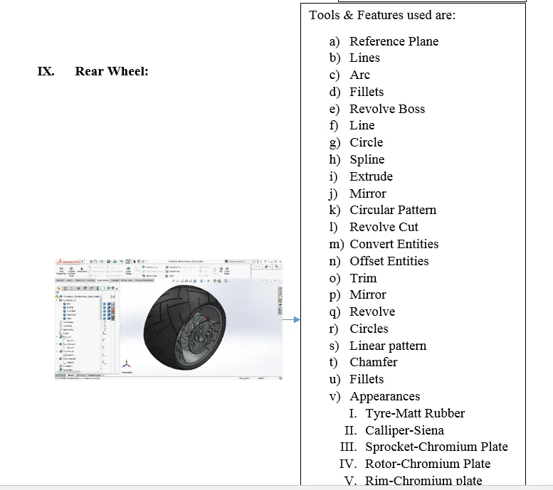
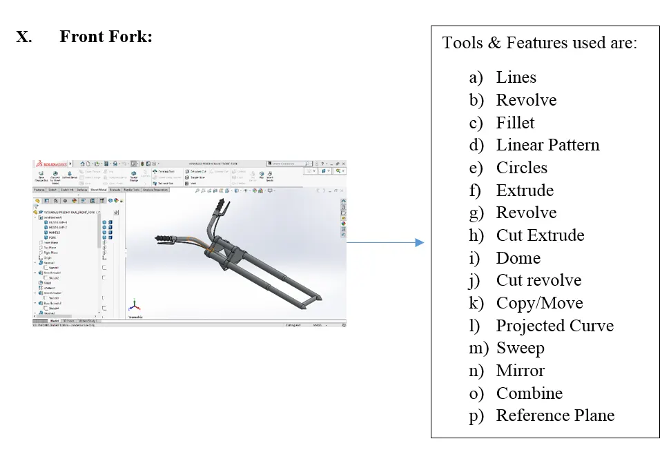
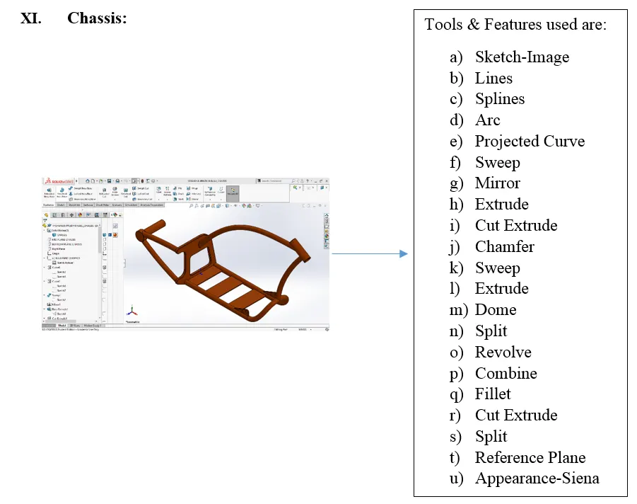
Individual parts of American Chopper are modelled using Solid Works part modelling each part is modelled using various features and tools based on their dimensions and method of approach.
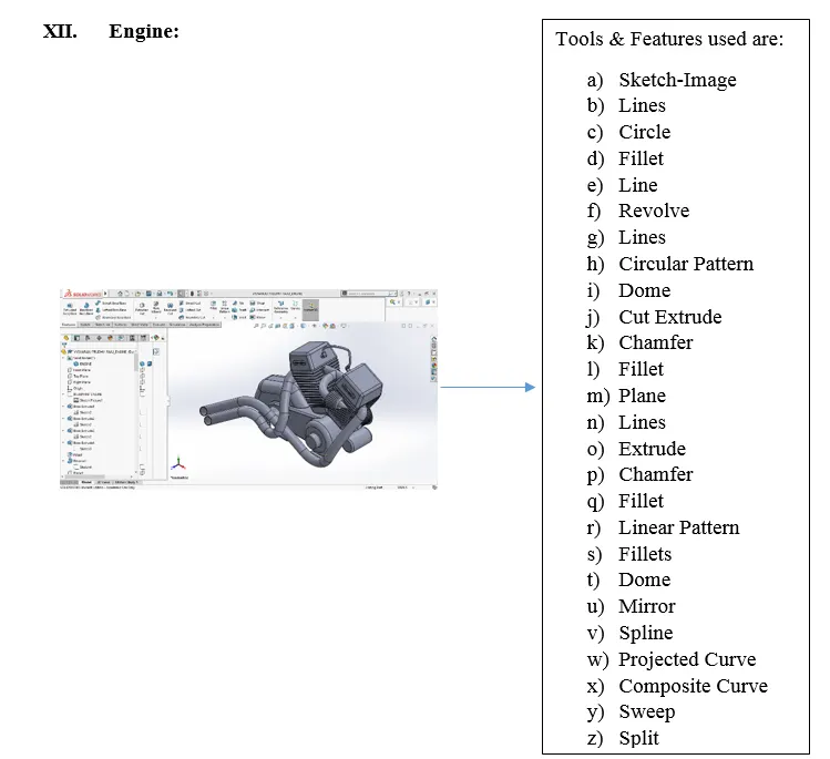
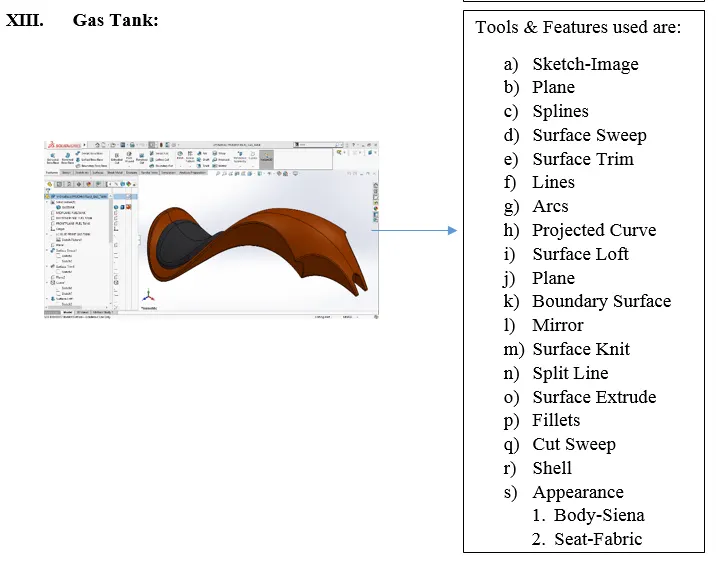
The Tools & Features used are:
- Line: It is an entity used in sketching workbench to create a line of different types like for construction, centre line and midpoint line based on their applications.
- Circle: It is also an entity used and available in sketching workbench to create a circle of different types like circle and perimeter circle based on their applications.
- Spline: It is also an entity used and available in sketching workbench to create a spline of different types like spline, style spline and equation driven curve based on their applications.
- Rectangle: It is also an entity used and available in sketching workbench to create a rectangle of different types like corner rectangle, centre rectangle, 3 point corner rectangle, 3 point centre rectangle and parallelogram based on their applications.
- Arc: It is also an entity used and available in sketching workbench to create an arc of different types like centre point arc, tangent arc and 3 point arc based on their applications.
- Ellipse: It is also an entity used and available in sketching workbench to create an ellipse of different types like ellipse, partial ellipse, parabola and conic based on their applications.
- Slot: It is also an entity used and available in sketching workbench to create a slot of different types like straight slot, centre point straight slot, 3 point arc slot and centre point arc slot based on their applications.
- Polygon: It is also an entity used and available in sketching workbench to create a polygon and can change the number of sides based on their applications.
- Sketch fillet: It is also an entity used and available in sketching workbench to create a fillet or chamfer based on their applications.
- Point: It is also an entity used and available in sketching workbench to create point.
- Trim entities: It is a tool available in sketching workbench used to trim entities or extend entities based on the application the particular tool is used.
- Convert entities: It is a tool available in sketching workbench to project the sketch selected on the plane you are sketching and in this tool another option of intersection curve is there which is also used to project sketch.
- Offset entities: It is a tool available in sketching workbench to create an offset of sketch at a certain distance based on their applications.
- Mirror entities: It is a tool available in sketching workbench to create a mirror of sketch with respect to the axis selected based on their applications.
- Pattern: It is a tool available in sketching workbench in this tool two options are available linear sketch pattern and circular sketch pattern to create patterns of sketch based on their applications.
- Dynamic Mirror entities: It is a tool available in sketching workbench to create mirror of the sketch while drawing the sketch it is similar to mirror entities.
- Sketch Dimensions: It is a tool available in sketching workbench to create dimensions for the sketches to make constraint.
3D-Features are:
- Extrude Boss/Base: It is available in features tab used to add material to a closed sketch in which direction we want based on applications.
- Revolved Bass/Base: It is available in features tab used to add material to a closed sketch in revolving manner to which direction we want based on applications.
- Swept Boss/Base: It is available in features tab used to add material to a closed sketches along the guide curve based on applications.
- Lofted Boss/Base: It is available in features tab used to add material to a closed sketches of different sketches on different planes along the guide curve based on applications.
- Extrude Cut: It is available in features tab used to remove material from a solid body along the sketch in which direction we need based on applications.
- Revolved Cut: It is available in features tab used to add material by revolving along particular axis along sketch in which direction we need based on applications.
- Swept Cut: It is available in features tab used to add material to a closed sketch along the guide curve based on applications.
- Fillet: It is available in features tab used to make fillet or chamfer to edges of solid bodies.
- Linear Pattern: It is available in features tab used to pattern bodies, features, faces in linear or circular direction based on a single point and the direction we need based on applications.
- Draft: It is available in features tab used to create tapered surface by which angle you need and from which surface you need based on applications.
- Shell: It is available in features tab used to give wall thickness by removing all the inner material of a solid body except the given thickness based on applications.
- Mirror: It is available in features tab used to mirror the bodies or features with respect to plane based on applications.
- Reference Geometry: It is available in features tab used to create reference plane, axis, co-ordinate system or point based on applications.
- Curves: It is available in features tab used to project curves based on two curves on different planes and the composite curve which is used to combine the projected curves to make a single composite curve.
- Dome: It is available in features tab used to create closed surface in the form of circular or ellipse on an edge surface.
- Split: It is available in features tab used to split the body in two pieces along the sketch based on applications.
Surface Features used are:
- Extrude Surface: It is available in surfaces tab used to add material to a sketch with surface thickness in which direction we want based on applications.
- Swept Surface: It is available in surfaces tab used to add material to an open or closed profile with surface thickness along the path based on applications.
- Lofted Surface: It is available in surfaces tab used to add material to a different profiles with surface thickness along the guide curve based on applications
- Boundary Surface: It is available in surfaces tab used to create boundary surface between two profiles in two directions.
- Fillet: It is available in surfaces tab used to create a rounded internal or external face along the edges on surface.
- Trim Surface: It is available in surfaces tab used to trim surface where on surface intersects with another surface, plane or sketch.
- Knit Surface: It is available in surfaces tab used to combine two or more adjacent and non-intersecting surfaces together.
ASSEMBLY:
Assembly in the sense joining all the individual components/parts of a Model using mates (Constraints) which will give any motion or to be stationary with respect to another part. This will result in the complete model which we want to obtain.
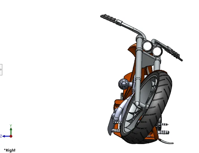
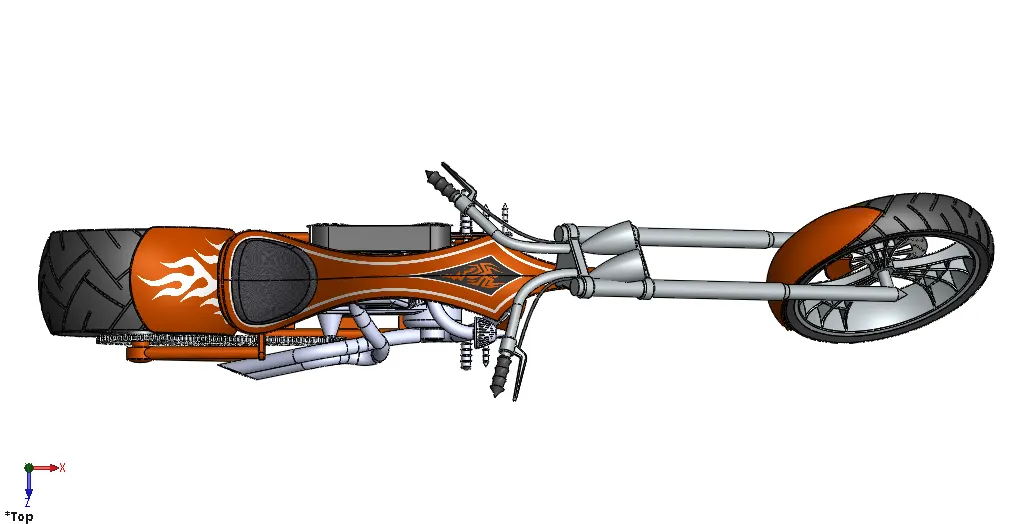
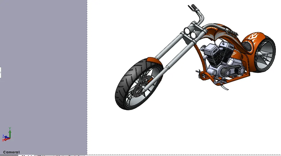
In American Chopper Modelling all the parts of the model are modelled individually and appearances are applied to each parts based on their material and each part is opened in assembly workbench and are joined using mates (Coincide, Distance, Parallel, Concentric, Angle, Width, Limit Angle, Tangent) and one of the part of the whole assembly is made to be fixed to make the whole assembly perfect that means all other parts are joined to that fixed component using mates. So if the Assembly is moved all the parts will also move with respect to the component which is made fixed
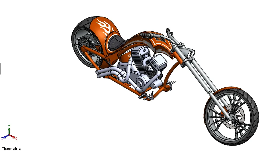
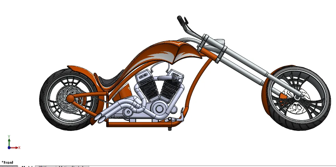
The Images of American Chopper Assembly are:
ISO-METRIC VIEW OF ASSEMBLY
FRONT VIEW OF ASSEMBLY
RIGHT SIDE VIEW OF ASSEMBLY
TOP VIEW OF ASSEMBLY
CAMERA VIEW OF ASSEMBLY
RENDERING:
In solid works we have Photo360 and Solid works Visualise to render any model, to make a model realistic as it looks in the outer environment, we can setup lights cameras in the way we want to look the model brighter and we can add decals to the parts which will give a good looking of the model we can customize the model by creating background scenes which will add environment to the model.
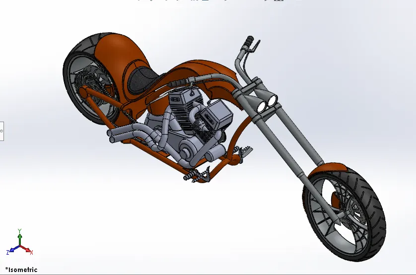
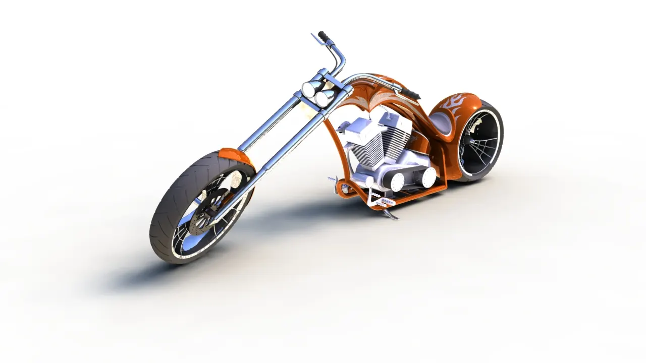
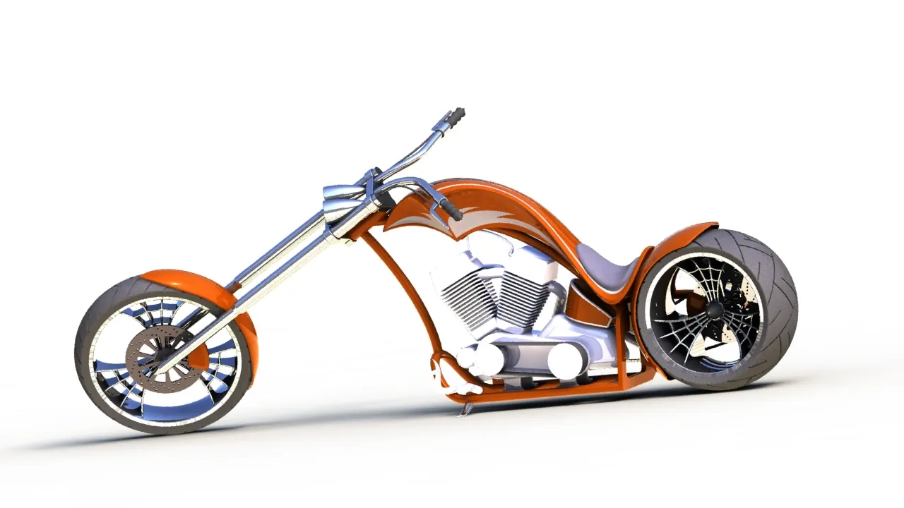
By observing the above images we can find the difference that after setting up lights and adding decals we can see the model is looking very good. We can also add the scenes to make it much better looking.
By using Photo 360 Final rendering option we can get the model as shown below.
CONCLUSION:
In this American Chopper parts modelling, assembly and rendering. I had modelled individual parts and added appearances in solid works part modelling workbench and assembled all the parts using mates in solid works assembly modelling and for the better looks added decals, lights, created camera views and rendered the final model using Photo 360.