Hood design-Week 2
DESIGN OF AUTOMOTIVE HOOD(BONNET)
AIM :
To design the hood(Bonnet) for the development & design consideration for the safety of pedestrian and the passengers.
OBJECTIVE :
- To design & Assemble the hood with the hinge, latch & striker.
- Design consideration of hood for the passenger & pedestrian safety.
- To find the moment of inertia of the hood.
- Draft analysis of hood for the manufacturing.
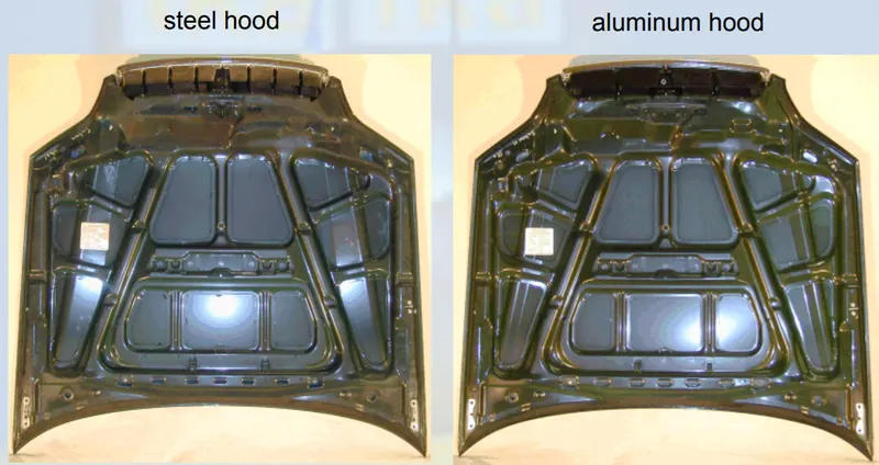
INTRODUCTION :
The car’s hood consists of an inner and an outer panel. The inner panel provides strength, while the outer panel is just a metal cover. The underside of the hood is often covered with a sound-absorbing material. Some high performance cars have ‘hood scoops’ which channel outside air directly to the air filter, which gives improved performance and efficiency.
The hood or bonnet is the hinged cover over the engine of motor vehicles that allows access to the engine compartment for maintenance and repair. On passenger cars, a hood may be held down by a concealed latch. On race cars, or cars with aftermarket hoods (that do not use the factory latch system) the hood may be held down by hood pins. A hood may sometimes contain a hood ornament, hood scoop, and/or wiper jets. Hood are typically made out of steel or aluminum, although aftermarket manufacturers may manufacture hoods out of fiberglass, carbon fiber, or dry carbon.
Requirement for hood :
- high global stiffness (bending, torsion)
- high local denting stiffness and strength (static and dynamic)
- dynamic stiffness (vibration behaviour)
- controllable deformation behaviour in frontal collision
- energy absorption at head impact
- minimized weight
- low costs
Hood Components :
- Outer Hood Panel
- Inner Hood Panel
- Hinge
- Latch & Striker
Hood outer panel :
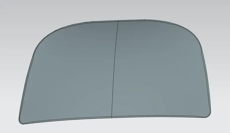
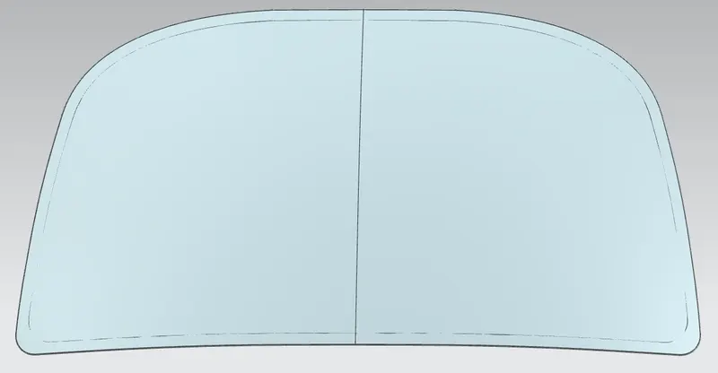
Hood outer panel is the extracted model from the A-surface also it gives proper look to the car.
Hood inner panel :
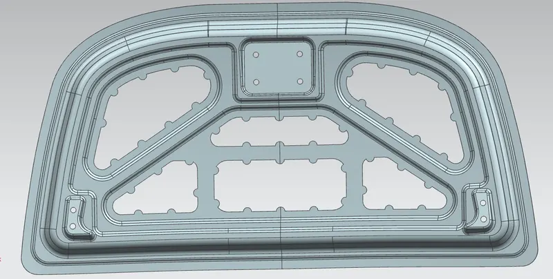
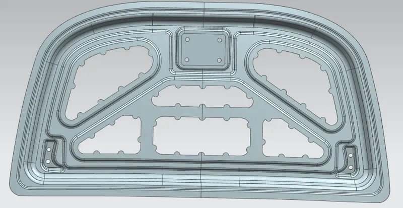
Hood inner panel which is used to give the strength to the outer panel.
Hinge :
The hood hinge is a mechanism that makes it possible for you to open and close your hood. This part allows the hood panel to move up and down, similar to how a hinge allows the movement of doors and windows. Each car typically has a pair of hood hinges (driver and passenger side) installed in the front of the vehicle.
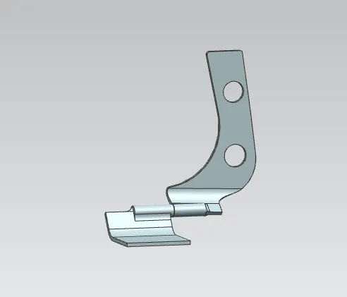
A hood hinge mechanism includes upper and lower brackets interconnected by pivoted links. An auxiliary hinge member is pivoted to the upper bracket and secured to the hood. The lower bracket is secured to the body. The upper hinge bracket and auxiliary hinge member are releasably secured to each other and normally move together as the hood moves between closed and partially open positions. When the auxiliary hinge member is released from the upper hinge bracket, the hood can be moved to various further open positions.
Latch & Striker :
The hood release system is common on most vehicles and usually consists of an interior hood latch handle, hood release cable and hood latch assembly. The hood latch handle is usually located below the steering wheel, beside the driver's seat or set into the door frame. On race cars or cars with aftermarket hoods (that do not use the factory latch system) the hood may be held down by hood pins. Some aftermarket hoods that have a latch system are still equipped with hood pins to hold the hood buttoned down if the latch fails.
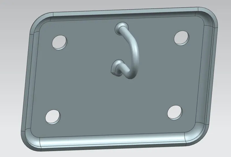
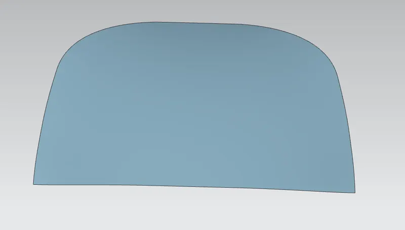
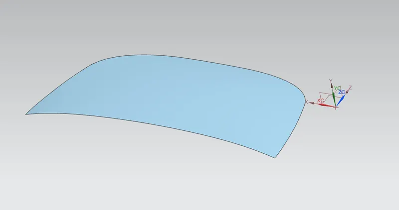
A-Surface for Hood :
Master Section :
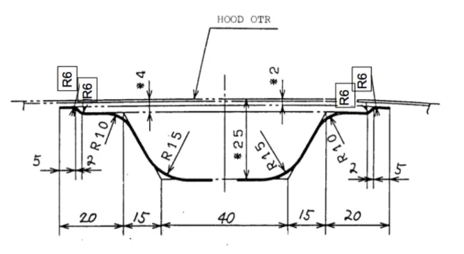
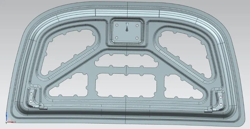
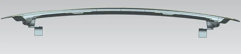
Design the Hood with the given A-Surface & master section.
Hood thickness,
- Outer Panel Thickness = 0.75mm
- Inner Panel Thickness = 0.75mm
- Reinforcement Thickness = 1.5mm
Design of Hood :
The designs are made as per the OEM design standards.
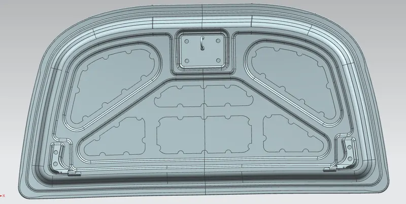
DESIGN CONSIDERATION FOR HOOD :
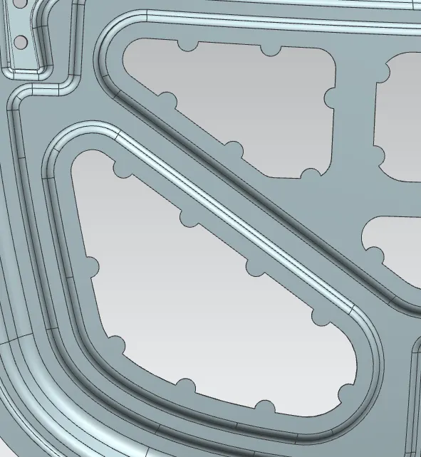
Emboss :
Emboss which gives the strength to the inner panel. this will help to desipate the force to outside of car while crash.
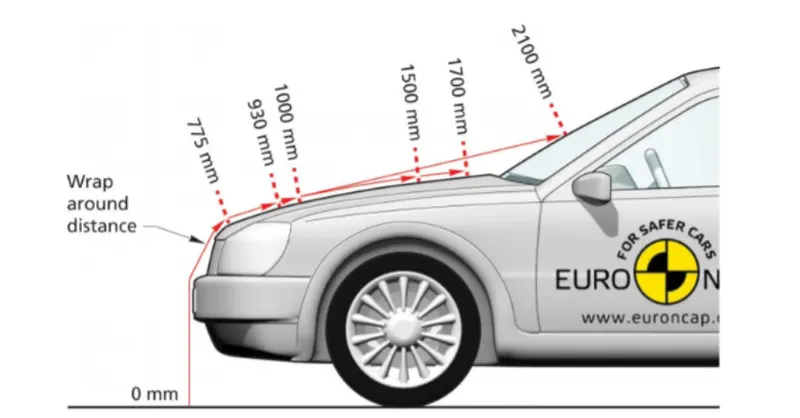
Wrap Around Distance :
WAD (Wrap-Around Distance) is the geometrically traced distance from the contact point with the Ground Reference Plane, vertically below the front face of the bumper, to any point on the vehicle front structure.
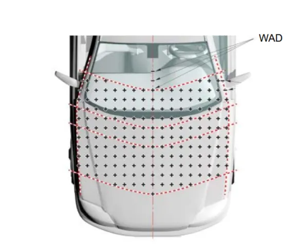
- Use a 1000mm straightedge to measure a vertical line parallel to the car's vertical plane, then tilt this line 50° towards the rear of the vehicle. Make the lower edge of this line 600mm tall. If the bonnet's upper-surface slopes 50° and the straightedge touches it in more than 2 places, fix the straightedge's rear tilt angle to 40°.
- Mark the points where the straightedge makes contact with the bonnet.
- If the lower edge of the straightedge makes contact first, make the marking there.
- If the upper edge of the straightedge makes contact first, follow the trajectory of WAD 1000.
- Remove the straightedge from the bonnet, running along the bonnet's cross-section, move it within a range of 100mm (with a ±3mm margin of error), have it make contact with the bonnet again and make a marking.
- Repeat steps (1) to (5) over the entire bonnet. Use a flexible ruler, etc., to connect the markings on the bonnet into lines. These lines need not be continuous and they can cross over emblems (within 100mm) and the like. These lines will be the Bonnet Leading Edge.
The Hood Side Edge Reference Lines,
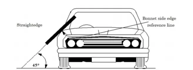
- Use a 700mm straightedge, fixed at 45° in relation to the reference plane parallel to the transverse vertical plane of the vehicle. Keep the straightedge parallel with the vehicle's cross section while making contact with the bonnet.
- Put a marking on the highest point where the straightedge and bonnet make contact.
- Remove the straightedge from the bonnet, move it forwards or rearwards within a 100mm range (with a ±3mm margin of error), touch it to the bonnet again, and make a marking on the highest point.
- Move the straightedge from the bonnet to A Pillar, and the roof (until it arrives at WAD 2100), and repeat steps (1) to (3). Ignore the fender mirror, door mirror, and antenna. Use a flexible ruler to connect the markings on the bonnet into lines. These lines will become the bonnet side edge reference lines. In this case, if the side edge reference lines are broken in the middle and are not consecutive, connect the various edges in the lateral direction of the vehicle.
Cut Section View :
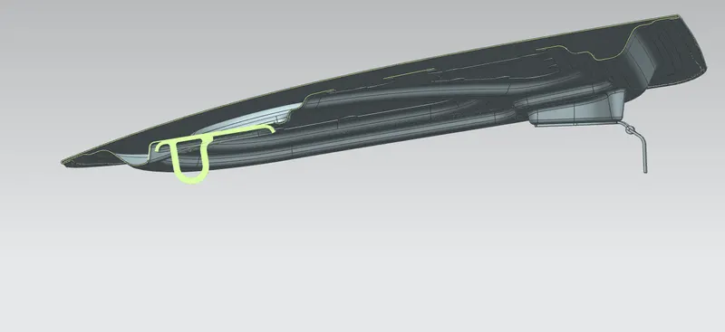
Hem Flange :
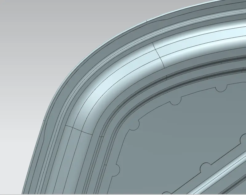
the hem are fold to edge of the part to create the round safe edge. Hems are created by bending the flange of the part in the hood design i used open hem to join the inner & outer hood panel.
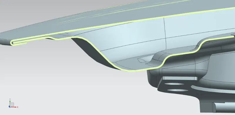
Rear Relief :
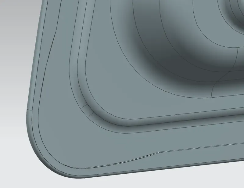
Front Relief :
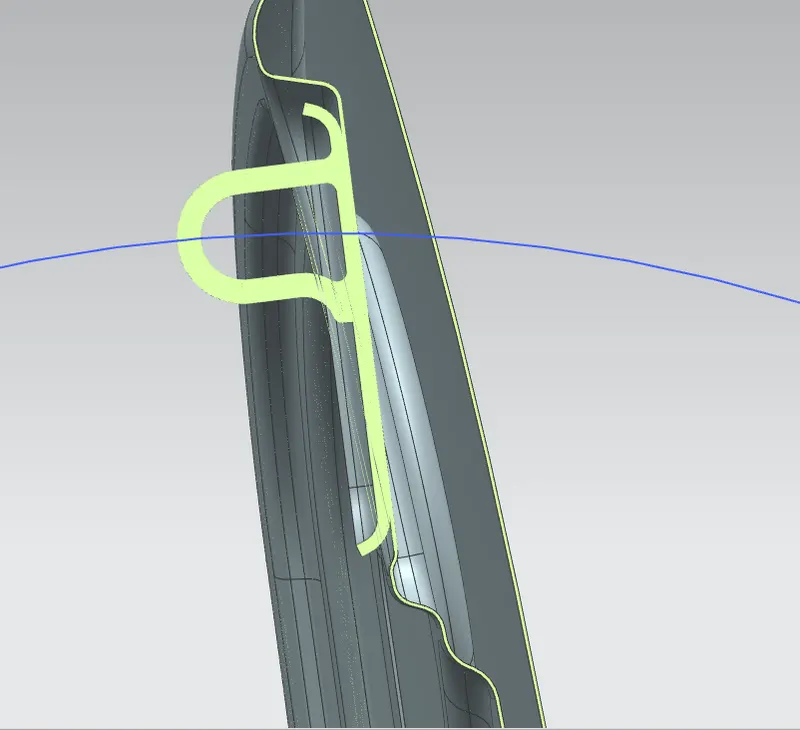
Position for the Striker :
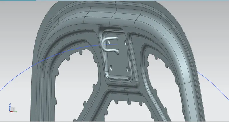
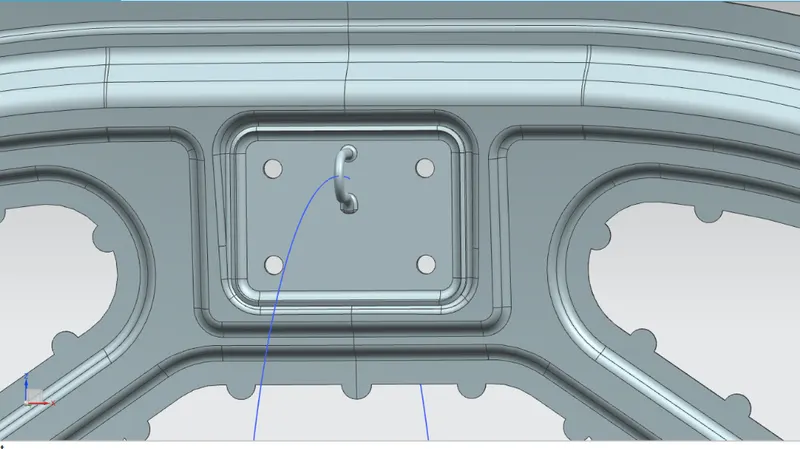
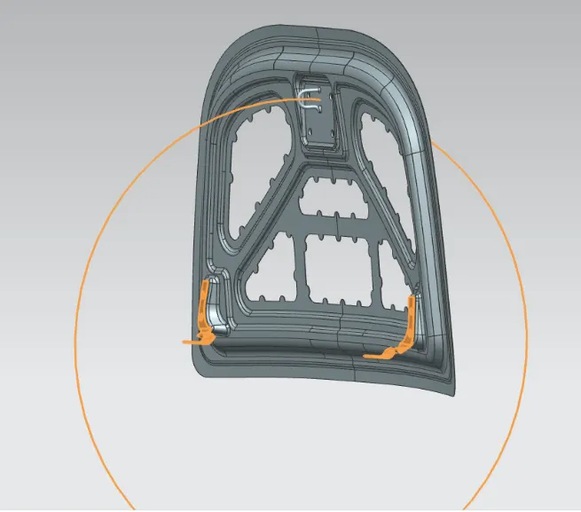
The striker should be positioned at the right direction otherwise the closing of the lid should be difficult. so to positioned the striker take the center axis between the two hinge and draw the circle. the striker should be perpendicular to the circle.
The below images will gives you the idea for locating the striker.
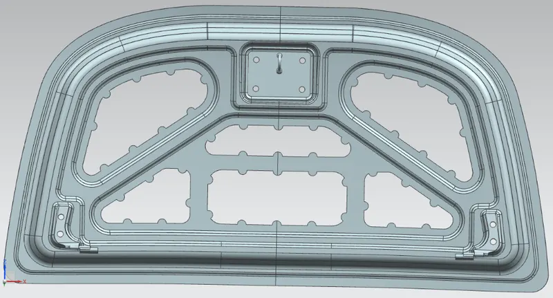
Mastic Seal :
Mastic seal which is like a rubber material used join the inner & outer panel and gives the strength to the hood also it helps to decrease noise & vibration. Each mastic seal which strengthen upto the 40 mm radius.
The below image shows the position for mastic points.
When the car crashes the force need to go outside of the car not inside to the passengers.
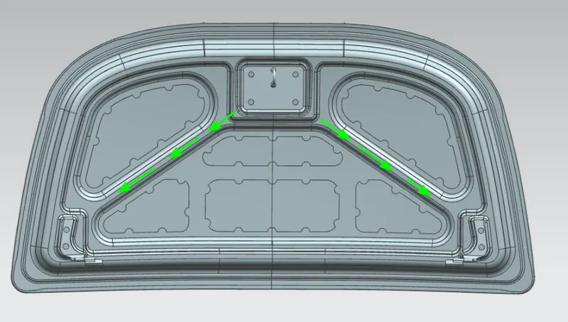
In the above image the arrow which shows the force travel outside.
Draft Analysis :
The below images shows the draft analysis of front & back side for hood.
As per the OEM standards the draft analysis should be minimum of 5 degree for the BiW component.
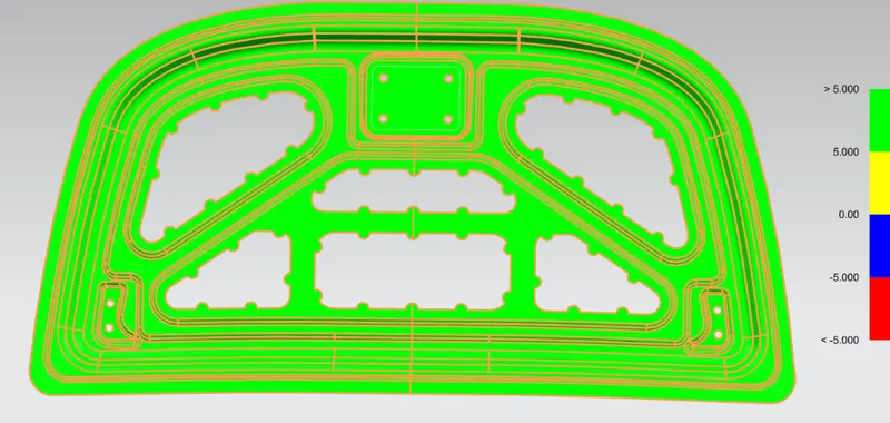
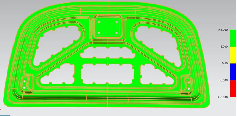
After the draft analysis the part is ready to manufacture.
Section Modulus for Hood :
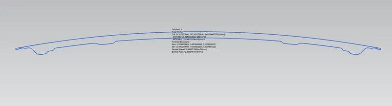
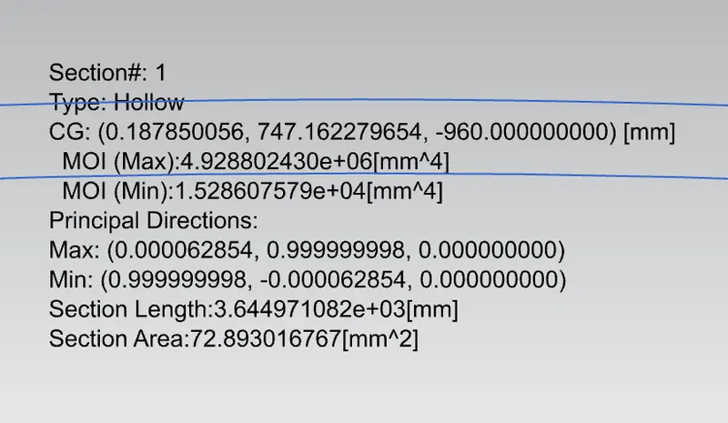
Section modulus(S) = Moment of inertia(I)/Distance between the netural axis and the extreme end of object(Y)
=1988.420817699 / 445
S = 4.46836
LINK FOR THE PART : HOOD ASSEMBLY
CONCLUSION :
Thus to design the hood(Bonnet) for the development & design consideration for the safety of pedestrian & the passengers and the draft analysis is made as per the OEM standards also the section modulus is calculated sucessfully.