Hood design-Week 2
AIM: Design and assembly of BIW Hood using NX-CAD application.
INTRODUCTION: The hood (American English) or bonnet (Commonwealth English) is the hinged cover over the engine of motor vehicles. Hoods can open to allow access to the engine compartment, or trunk (boot in Commonwealth English) on rear-engine and some mid-engine vehicles) for maintenance and repair.
In British terminology, hood refers to a fabric cover over the passenger compartment of the car (known as the 'roof' or 'top' in the US). In many motor vehicles built in the 1930s and 1940s, the resemblance to an actual hood or bonnet is clear when open and viewed head-on; in modern vehicles it continues to serve the same purpose but no longer resembles a head covering.
On front-engined cars, the hood may be hinged at either the front or the rear edge, or in earlier models (e.g. the Ford Model T) it may be split into two sections, one each side, each hinged along the centre line. A further variant combines the bonnet and wheelarches into one section and allows the entire front bodywork to tilt forwards around a pivot near the front of the vehicle (e.g. that of the Triumph Herald).
Hoods are typically made out of the same material as the rest of the body work. This may include steel, aluminum, fiberglass or carbon fiber. However, some aftermarket companies produce replacements for steel hoods in fiberglass or carbon fiber to make the vehicle lighter.
DESIGN SPECIFICATIONS FOR HOOD :
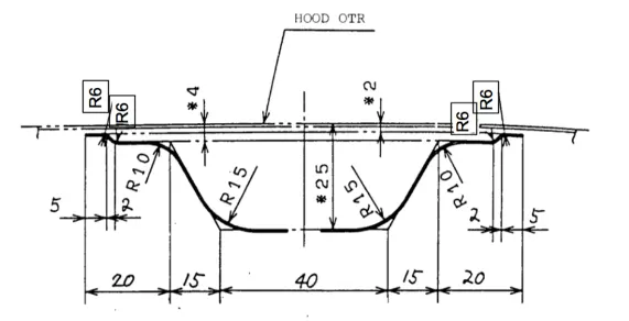
Hood Thickness Information:
- Outer Panel Thickness = 0.75mm
- Inner Panel Thickness = 0.75mm
- Reinforcement Thickness = 1.5mm
SEQUENCE OF OPERATIONS FOR DESIGNING A HOOD:
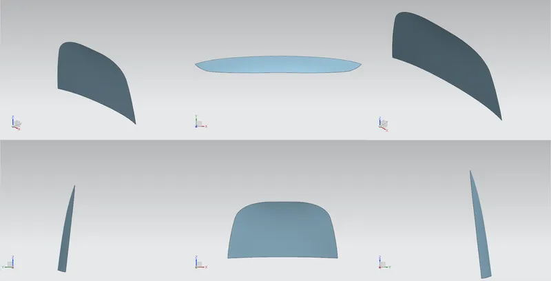
1. Design of outer panel of a hood
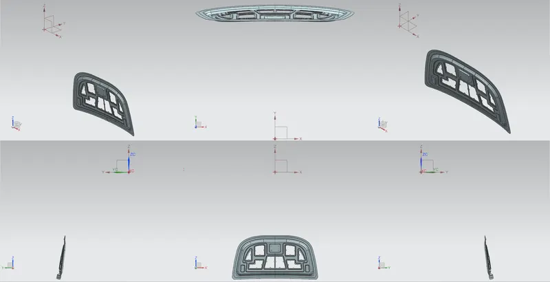
2. Design of inner panel of a hood
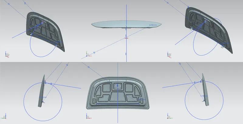
3. Design and assembly of hinge
4. Design of striker
5. Hemming and application of reliefs in outer panel to inner panel
6. Latch trajectory motion and assembly of all the components
HOOD INNER PANEL:
HOOD OUTER/SKIN PANEL:
HINGE , HOOD AND STRIKER ASSEMBLY:
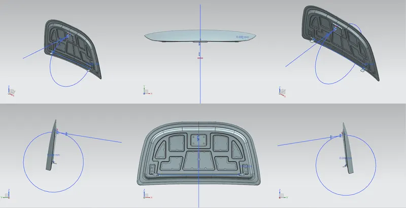
LATCH TRAJECTORY MOTION AND FINAL ASSEMBLY:
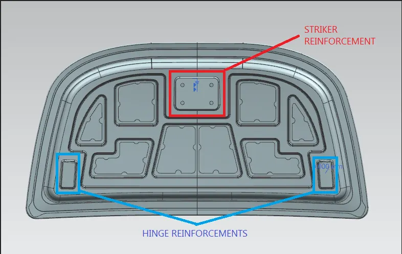
STRIKER/LATCH AND HINGE REINFORCEMENTS:
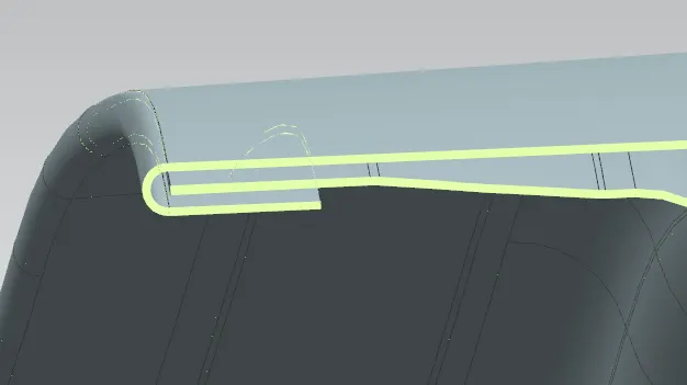
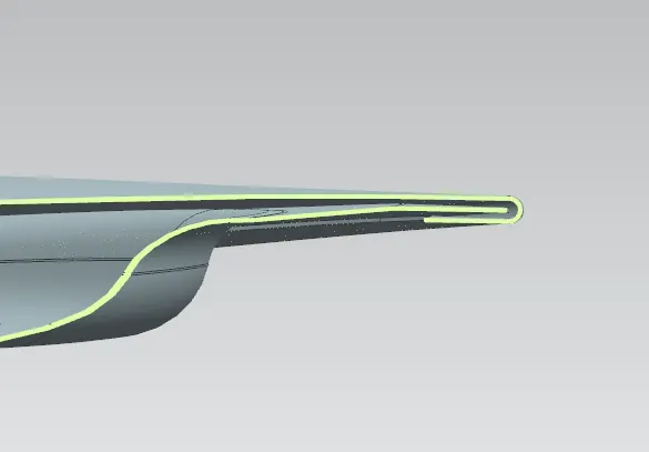
HEMMING OF OUTER PANEL:
Hemming is a sheet metal forming process in which sheets are joined by bending it usually to 180°. Automotive body panels and automotive parts such as deck-lids, trunk-lids, doors, hoods and tailgates are formed by hemming process.
TOOLS USED IN HOOD DESIGN:
SKETCH TOOLS: Tools like point, line, curve, rectangle, circle,arc,profile,spline,construction line,profile are mainly used while doing thee basic 2-D sketch.
ASSEMBLY TOOLS: 1. MOVE COMPONENT: This command is used to movie any particular part with respect to the datum planes and axis directions.
2. ADD COMPONENT: This command is used to add any particular model or sub-assembly into a main assembly.
3. MIRROR ASSEMBLY: This command is used to mirror or replicate any sub-assembly with respect to the datum planes.
4. ASSEMBLY CONSTRAINTS: This command includes touch align, concentric, distance, fix, parallel, perpendicular,angular,center, bond, fit, align,etc. These commands are mainly used to join two or more components together in an assembly mating process.
CURVE TOOLS: 1. PROJECT CURVE: This command is used to project the selected curves on the selected body faces with respect to the datum planes.
2. OFFSET CURVE IN FACE: This command is used to offset the required edges of face by selecting the edges of a face and giving them direction and distance to offset on that particular face.
3. CURVE ON A SURFACE: This is also a similar tool like offset curve which is used to create curves on the surfaces.
SURFACE TOOLS: 1. LAW EXTENSION: It is used to extend an existing surface or sheet based on the laws for distance and the angle of the extension. Law Extension creates flanges or extensions when a particular direction is important or when it is necessary to reference the existing face.
2. FACE/EDGE BLENDS:Face Blend is primarily used to blend between faces of separate bodies. It can also be used to blend between faces of a single body.Edge blend command creates smooth tangent faces between faces which connected on edge.
3. OFFSET SURFACE:This command is used to create an offset of one or more existing faces. The result is a new body (or bodies) with an offset relation to the chosen faces.
4. TRIM SHEET/ TRIM BODY: This command is used to trim sheet bodies to intersecting faces and datums, and projected curves and edges.
5. EXTEND SHEET: This command is used to extend the surfaces at the edges by selecting the required edges and giving then the distance.
6. SEW:Sew command is used to join two or more sheet bodies into a new single sheet body.
7. THICKEN: Thicken command is used to offset one or more connected faces or sheets into a solid body.
8. EMBOSS: Emboss command is used to create an embossing by modify a body with faces made by projecting a section along a vector, with options for end cap location and shape.
CONCLUSION: All the parts of hood are designed as per the considerations and design requirements and the final assembly is performed for all the associated parts of a hood.