Hood design-Week 2
Hood Assembly
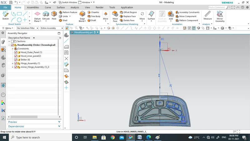
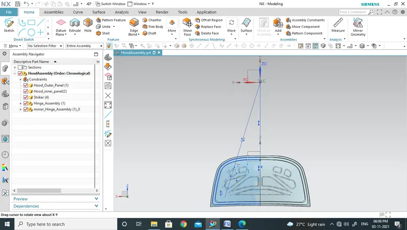
Objective: To create hood assembly with different parts in it.
Introduction: Hood is a part of car beneath which the engine and the other main parts of a car like transmission system, radiator are present.
Design Methodology:
- Open a new assembly file in NX CAD environment and name it as HoodAssembly.
- Go to Assemblies and Add Components of the assembly.
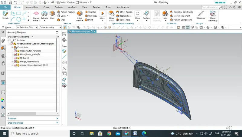
- The different components of the hood assembly are:
- Hood Outer panel.
- Hood Inner panel.
- Hinge assembly.
- Striker.
We have the Outer panel, Hinge assembly and striker given to us. The inner panel is what we have to create.
Steps to create inner panel:
- In Assemblies there is an option called Wave Geometric Linker. This helps us to copy the geometry of one part to the work part in an assembly. So, using wave geometry linker we can copy the geometry of outer panel to the inner panel which is now the work part.
- Create Feature group of this file and name it as parent file.
- Offset the parent surface to 0mm and get another surface.
- Create a feature group of this surface also and name it as working surface.
- Offset the working surface to 2mm downwards as mentioned in the master section.
- Use offset curve in face and create a curve on the surface which is 20mm offset inwards. While using offset curve in face if we select fillet (best fit) and radius (30mm) under Fillet Sharp Corner option, the sharp corners of the offset get filleted.
- Using trim sheet trim off the inner part of the sheet. Now a 20mm strip will be left.
- Now again offset the working surface to 4mm
- Using Offset curve in face offset the edge of the new sheet to 40mm
- Again, use trim sheet to trim off the outer side of the sheet (fig 1).
- Using Through curves create a surface between the two sheets (fig 2).
- Now, again offset the working surface to 25 mm downwards and then using offset curve in face offset the edge of the curve to 55mm
- Use Trim sheet to trim off the outer sheet.
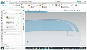
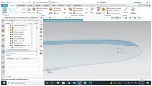
Fig 1 Fig 2
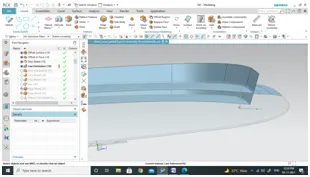
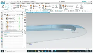
Fig 3 Fig 4
- Use Law extension extend the edge, creating a surface (fig 5).
- Using trim and extend trim off the unwanted parts of the sheet to get the desired output (fig 4).
- Now, use face blend and edge blends to create blends where ever necessary.
- After applying blends sew all the sheets together.
- Make a sketch leaving some space for hinges emboss and striker emboss.
- This sketch is made on the XZ plane and is projected on to the sheet using project curve option. Fig 5.
- Create a surface along the sketch using law extension. Fig 6.
- Offset the lowest surface to 15mm upwards
- Using trim and extend cut the offsetted surface in the shape of the law extension. Fig 7
- Use trim sheet to obtain the emboss as shown in the Fig 8.
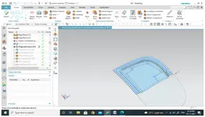
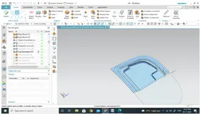
Fig 5 Fig 6
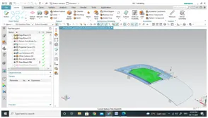
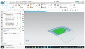
Fig 7 Fig 8
- Now make a sketch for creation of reinforcement for hinge assembly. When a hinge is mounted, it adds weight because of which the strength of the hood reduces. So we need to make reinforcement.
- Using emboss command make the hinge emboss and then apply blends to the edges using edge blend.
- Go to Assembly Constraints and apply Align constraint between hinge’s back surface and face of the emboss.
- The center line of hinge should be parallel to the X-axis. Apply parallel constraint for this.
- Obtain curve from hinges using wave geometry linker.
- Use Point under curve tab, to create a point. Use Arc/ellipse /sphere center option to create a point at the center of the composite curve.
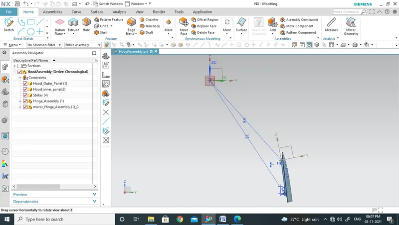
- Create a center point on the other hinge in the same way. Join the two centers with a line.
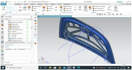
- Now, with the mid-point of this line as center point, construct a circle. Draw a tangent line to this circle from where the striker is located. Also, draw a line from the center of the hook. Apply coincide constraint the points of this line and the points of the tangent.The striker moves to its correct position. Apply touch constraint so that the striker is fixed wrt the hood.
- The striker moves to its correct position. Apply touch constraint so that the striker is fixed wrt the hood.
-
-
- Make embosses on the inner surface in different shapes. Use emboss command for this.
- To get an even surface for mirroring, extend the sheet by 5mm and then trim it using mid plane as boundary. Use mirror geometry to mirror the entire geometry.
- Using extend sheet, extend the inner most edges for applying
- Using thicken; thicken the inner panel by 75mm in the upward direction.
-
Hemming:
- Make outer panel as the work part.
- Offset the outer edge towards inwards to about 5mm.
- Use law extension and create a surface which is symmetric about the edge of the outer panel.
- Offset this surface inwards to about 15mm.
- Offset the outer panel to 15mm downwards.
- Using trim sheet, trim off the inner part of the offsetted surface.
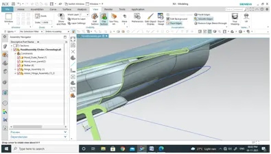
- Use Face blend(3- face) to create a hem.
-
- Anbu Bmhow to create the mastic points in hood