Hood design-Week 2
HOOD ASSEMBLY
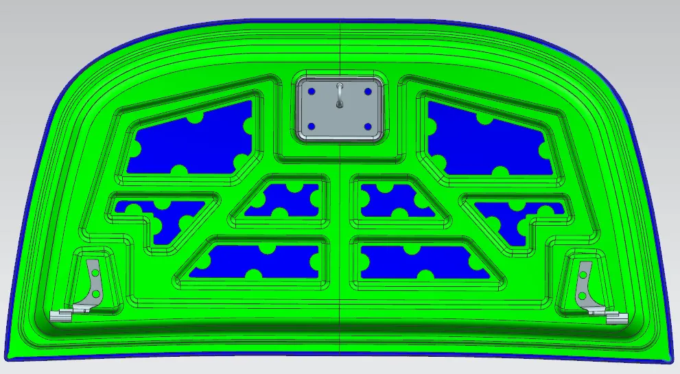
From the given class A surface (outer panel) ,the inner panel is made by following the design requirements and necessary embosses and cut outs are made acording to the design norms. Hinges are mounted on the inner panel by creating seperate embosses for it. As well as the striker is also mounted on the pannel by creating a embossed region on the inner panel. The cut outs are created on the inner panel for pedastrian safety and also providing space for mastics. The outer and inner panel is joined with help of mastic gel , which also gives NVH to the hood. The edge of the outer panel is bent so that it could be joined with the inner panel, this process is called hemming. The area of moment of inertia of the hood assembly was found by section inertia analysis in NX. Moment of inertia is used to find out the section modulus, Z=I/Y. Draft analysis is done and the hood assembly is clearing the analysis , minimum draft angle of 7 dgrees is given to the assembly. NOTE: "DUE TO FILE SIZE CONSIDERATION , I HAVE SPLITTED IT INTO TWO FILES AND UPLOADED IT. PLEASE EXTRACT BOTH THE FILES AND COMBINE BOTH OF THEM ,SO THAT "HOOD ASSEMBLY MAIN" FILE CAN BE OPENED". https://drive.google.com/file/d/1kuVyt8v89OPwrCulvJimYu5wOjzan04m/view?usp=drive_link THIS LINK HAS THE SINGLE FOLDER OF THE HOOD ASSEMBLY FILE