Hood design-Week 2
AIM:-
To Design Hood Outer Panel, Inner Panel and the necessary reinforcements by following the Master Section mentioned with the Design parameters explained in the videos & detailed report about the Hood Design which includes a detailed explanation about hood and its components, Latch Trajectory, Mastic Data, Emboss Definitions, Manufacturing process like Deep-Drawing and Hemming, and all the parameters followed in the design.
HOOD:-
A car hood, also referred to as a “bonnet” in some countries, is the hinged cover that rests over the engine bay of a front-engine vehicle. The car hood protects the engine and connected parts from the elements while providing easy access for repairs and maintenance.Car hoods are typically constructed from steel and sometimes from aluminum. Aftermarket car hoods may be constructed from various other materials, including carbon fiber, fiberglass, or dry carbon. Hood consist of inner panel and outer panel. The outer panel is the surface which we seen from outside and the inner panel which provides strength to the hood and helps in fixations of reinforcements, striker ,hinges and its is attached to hood outer panel in the engine compartment side.
The hood is classified into two types:-
- Active hood
- Passive hood
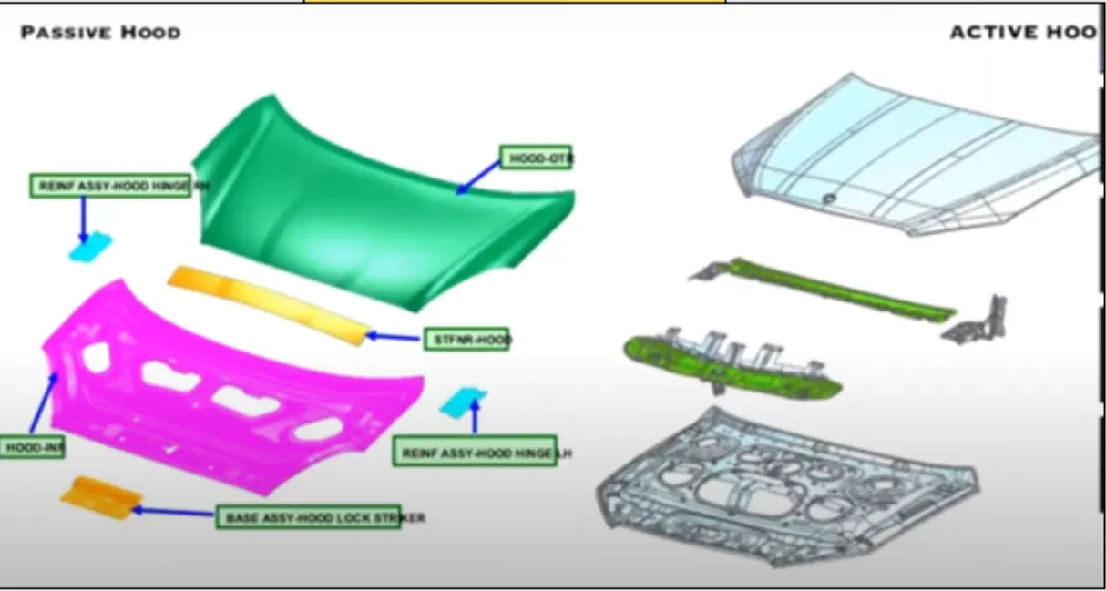
Active hood:-
It is a type of hood which is mostly made for global market as per the european standards which consists of large reinforcements for the inner panel and for the attachments like striker, hinges. It also has good safety standards according to Euro Ncap and the price of the Car is higher when compared to the cars having passive hood.
Passive hood:-
It is a type of hood which is mainly for indian market satisfying the standards with respect to the indian market. The inner panel of the hood itself is act as a improvement in strength and safety when compared to the Active hood and it has less reinforcements and safety standards will change according to the indian market.
Design consideration of Hood:-
- Hood opening angle
- Hood support stay
- Hood inner panel structure
- Pedestrian safety
Hood Opening Angle:-
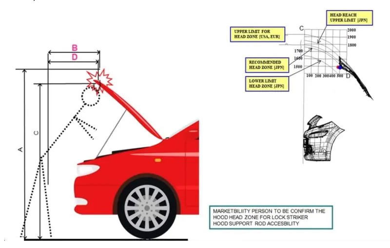
The hood opening angle must differ from country to country for example as it is mentioned in the above image people from europe and american regions they will be around 6feet height and it is the average height in those country. In India people will be having an average height of 5.5feet similar to japan. According to the countries market requirement it will be decided.
Hood Support Stay:-
There are two types of hood stay
- Support rod
- Gas stay
Support rod:-
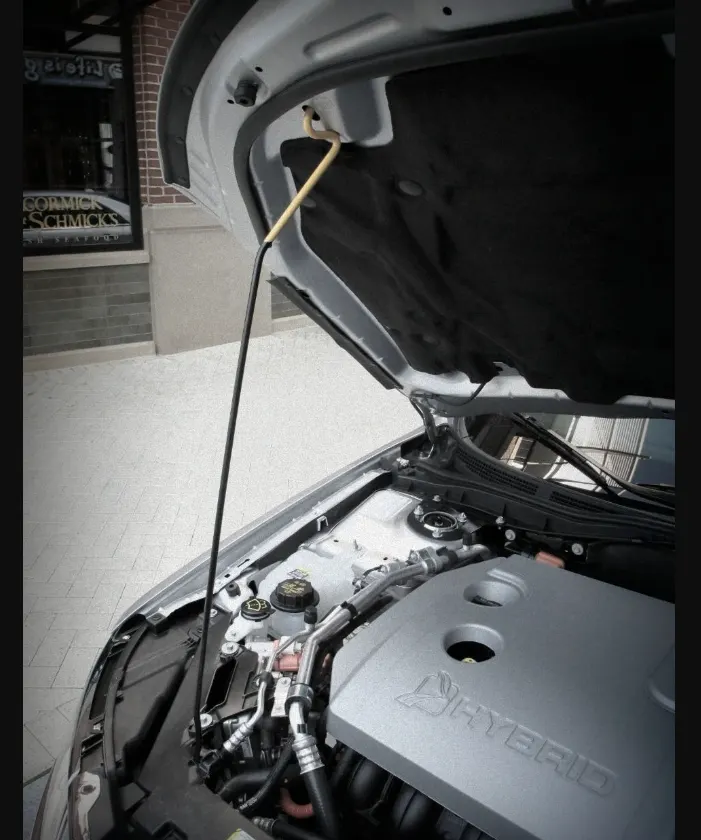
The above image is the support rod and it is simple when compared to the gas stay. Both price and maintenance purpose.
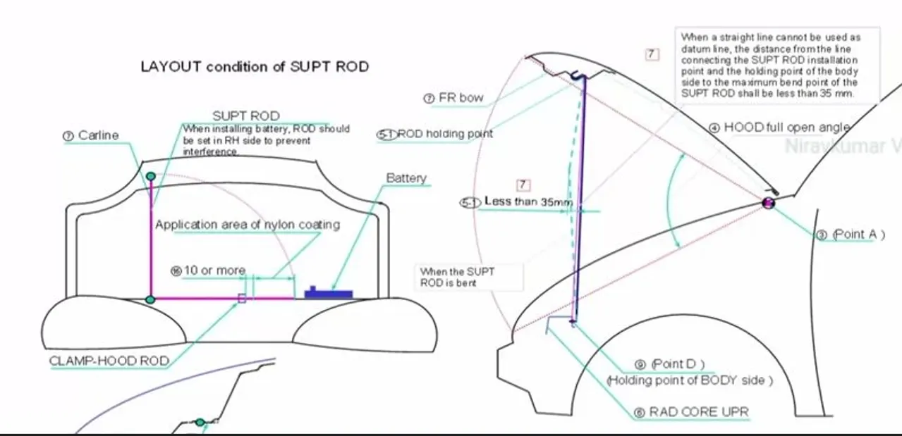
The above image shows that the support rod should be placed on the opposite side of the battery compartment in the car so that we can easily remove battery if we want. The support rod bending between the starting point and end point should not be less than 35mm due to the stress consideration if it is more than 35mm it may have a reduction in stiffness due to the load from the hood and may bend more after some time. According to the opening angle of the hood support length will be decided.
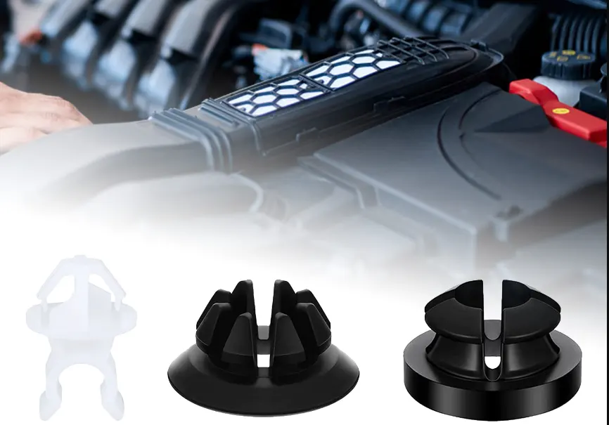
The above image is the grommet clips which is used to hold the support rod in engine compartment and hood.
Gas stay:-
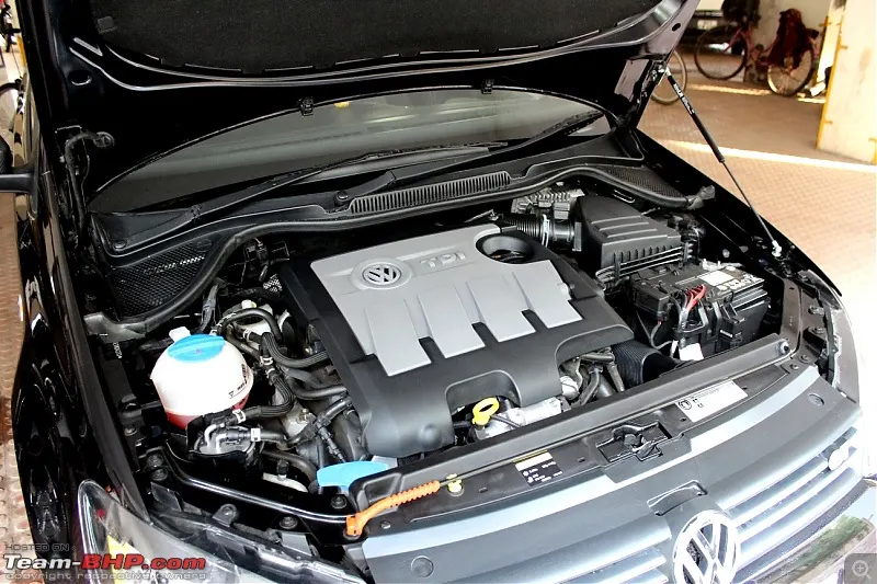
A gas stay is used to open the hood, keep it in an opened state and then closing the hood. One side of gas stay is mounted on body side and other side is mounted on the hood this is automatic process, that is the gas stay uses an actuator to open the hood. According to the opening angle and length of the hood, gas stay opening length is decided.
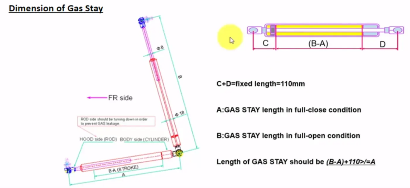
The dimensions mentioned in the above image is an example but according to different standards follwed by the industry it will differ.
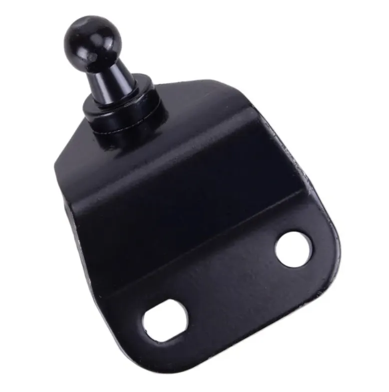
The above image is the ball stud which is used for the fixation of gas stay in both engine compartment and the hood inner panel. Reinforcements also created accordingly.
Pedestrian Safety:-
The side reference line and wrap aroud distance of the car is the main factor in the pedestrian safety
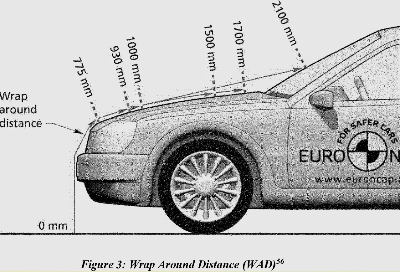
The wrap around distance is the trace of the points received on the front structure, when one end of the flexible tape required length held at ground reference level and the other end in contact with the front structure.
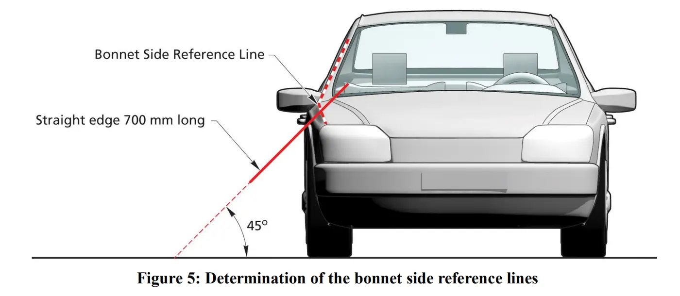
The side reference line means the trace of the highest contact point between straight edge inclined at angle of 45deg and side of the vehicle.
These are the things which the head impact of a child or adult over the hood region is measured these test are taken by the Europe Ncap organisation for the pedestrian safety ratings of the car.
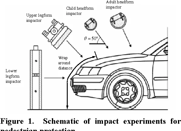
The above diagram shows the impact prediction of a child and adult over the hood.
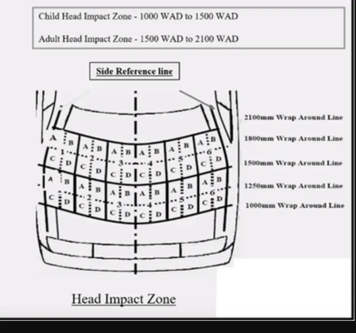
As shown in the above image the child head impact will be around 1000-1250 wrap around line and for adult
it will be around 1500-1800 wrap around line these are the values for this type of hood and it will varies according to the hood design and size.
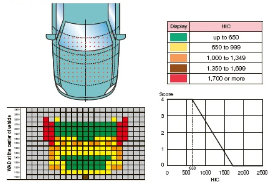
The above image shows the head injury criterion score of a car, the green regions are the zones where the pedestrian can have a less impact when he experiencing a head impact during an accident. Also in the lower region it is for the child head impact zone where they can experience less impact during an accident.
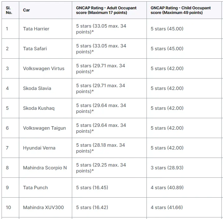
The above image represents the pedestrian safety ratings of the cars in india with respect to the global Ncap ratings. These ratings are based on the HIC values of the car hood.
Hood Outer and Inner Panel Design:-
The Class A skin of the hood outer panel will be given by the styling team. With respect to the engine to hood clearance gap and other components. They will do the benchmark and come up with ideas it is the industry perspective that how they will design a hood inner panel.
But here i have a created the hood inner panel with the given mastersection and cosidering the design standard rules.
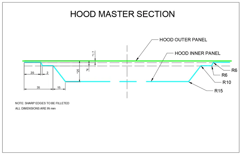
The above image is the given mastersection for the hood inner panel.
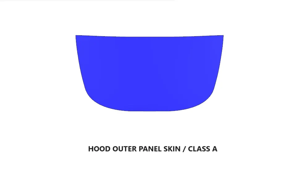
The above image is the given hood outer panel.
Hood Inner Panel creation:-
Using wave geometry linker option to extract the outer panel skin for creating the inner panel.
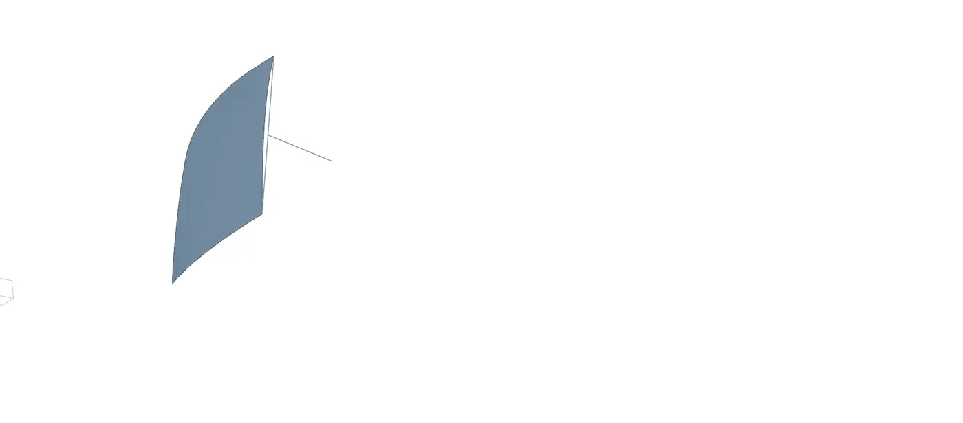
The linked face is trimmed with respect to the datum plane and created a line between the two edges of the trimmed inner panel. Then created a tooling axis from the midpoint of the created line the tooling axis should be perpendicular to the line.
According to the given mastersection the outer panel is offseted to 1.7mm for creating the first flange
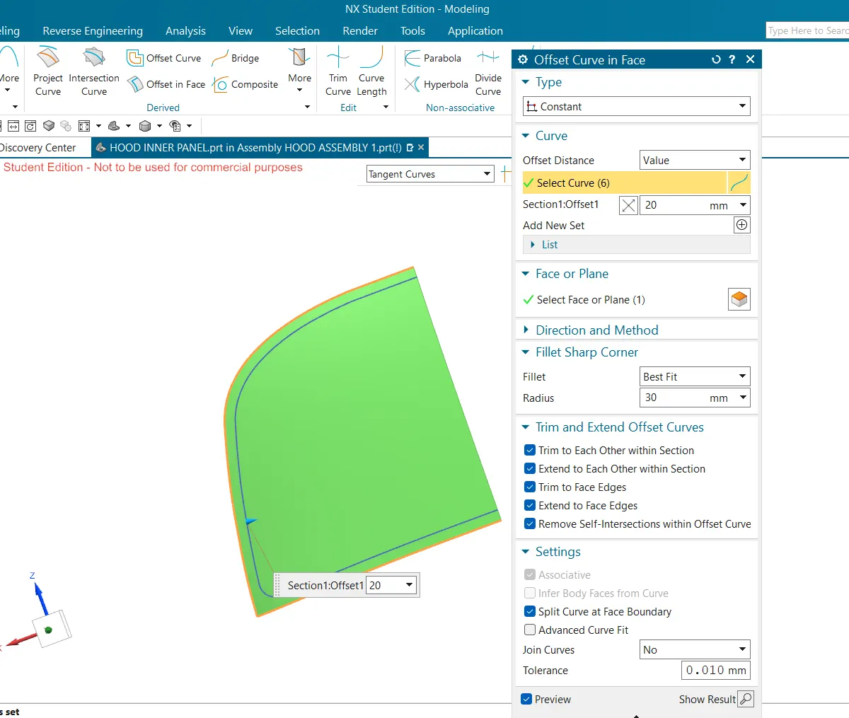
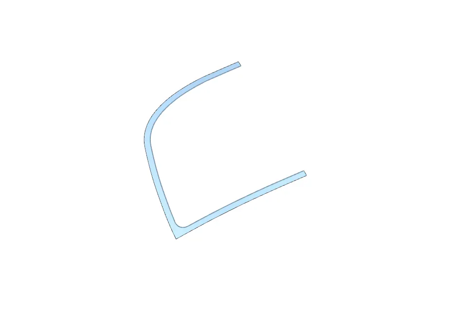
Using the offset in face tool to create the offset face for the first flange creation which is 20mm and trimmed it to form the first flange for the inner panel according to the mastersection data.
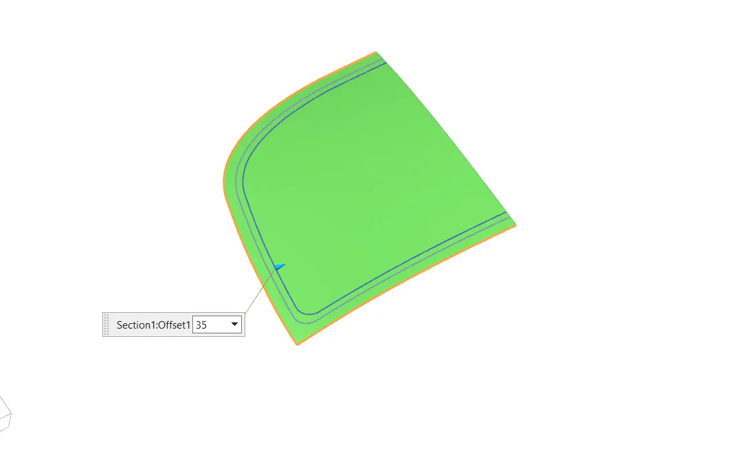
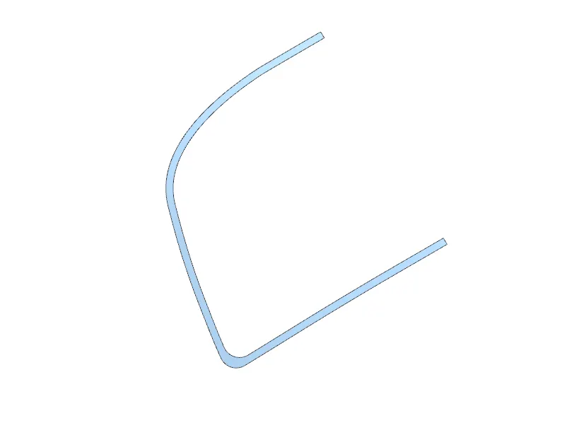
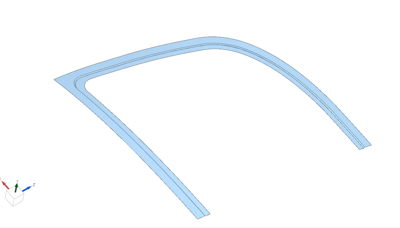
Then refered the master section and offset the inner panel to 4mm then created the second offset face curve to create the second flange which is 22mm and 35mm and trimmed it. Using the Through curves tool connected the 1st and 2nd flange.
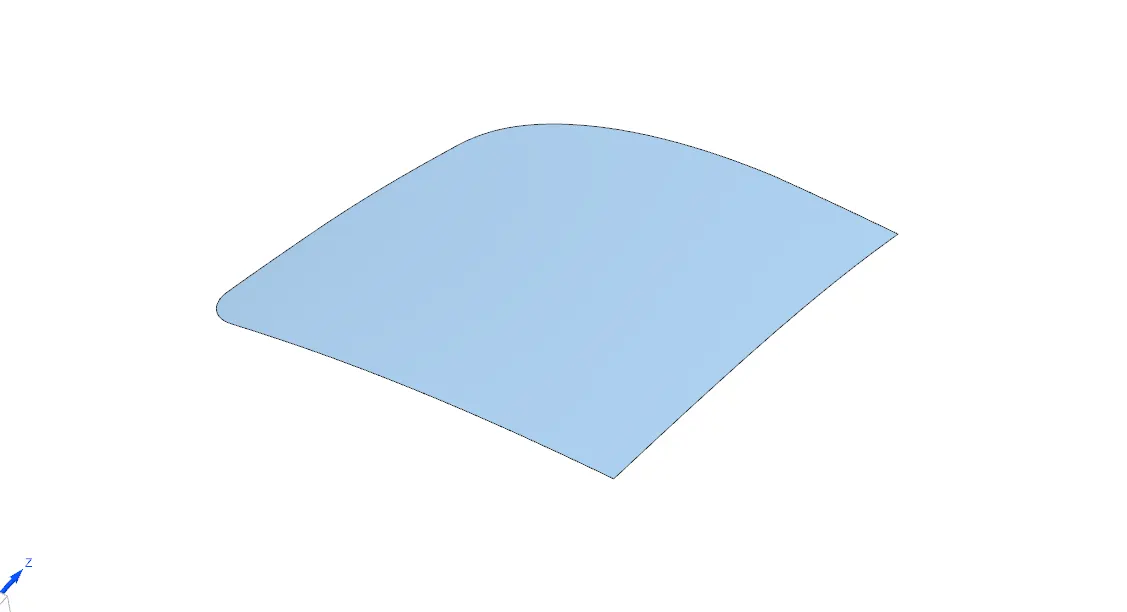
Then refered the master section and offset the inner panel to 25mm then created the third offset face curve to create the third flange which is 35mm and 50mm and trimmed it.
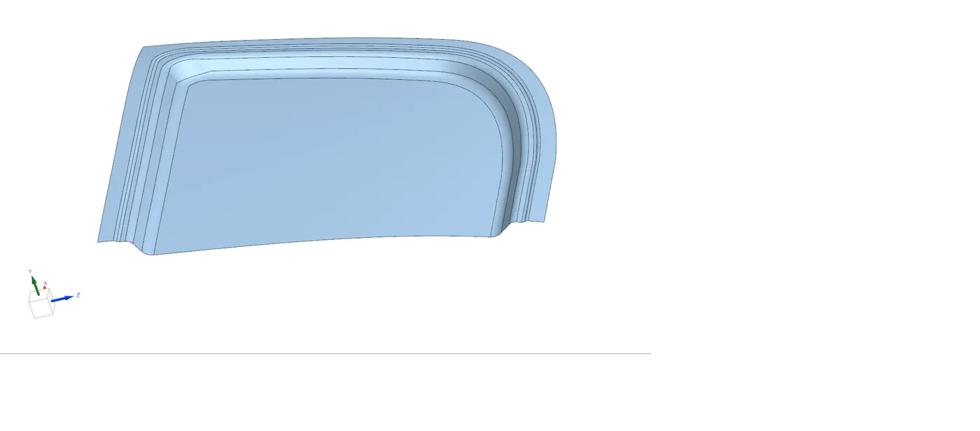
After creating all the flanges given a face blend for every flanges with respect to the mastersection and created a innerpanel cutout.
Emboss:-
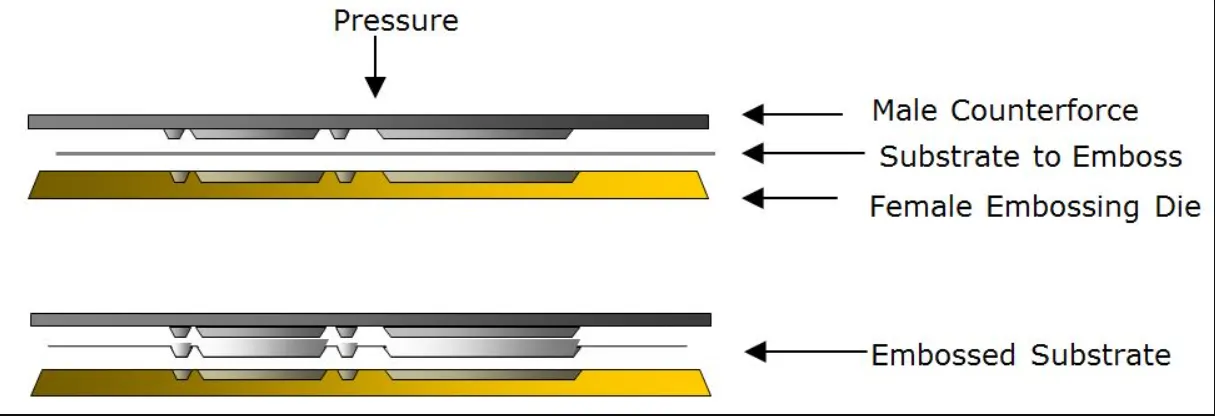
The embossing is a process where the sheetmetals are changed into desired shapes with the help of die and a counterforce as we seen in the above image, sheet metal embossing is a stamping process for producing raised or sunkens designs or to produce a relief in sheet metal.This process can be made by means of matched male and female roller dies or by passing the sheet or strip of metal between two rollers of the desired pattern.
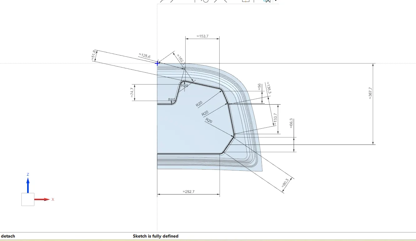
Creating a fully defined sketch in the respective datum plane and projected the sketch using project curve option over the desired face of the inner panel and Using emboss command created the emboss on the created inner panel.
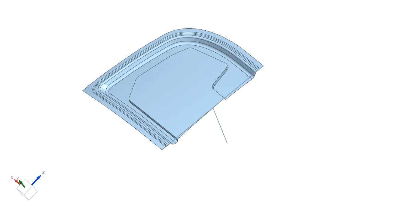
The above 1st emboss is created with the draft of 10deg along the tooling direction with 10mm depth, for biw components the minimum draft angle should be 7deg as per the design guidliness which helps in ejecting the component easily with increased die and tool life. The edge blend is given for both the edges of the created emboss as per the guidliness minimum fillet radius should be 3+the thickness of the component here i gave 6&5 mm for the bottom and top edges of the emboss. To ensure that the outer panel fillet edge and the emboss fillet edge had minimum distance of 5-10mm, in sheet metal design especially in the edge to edge of a fillet it should be a minimum distance of 5-10mm to make the stamping process feasible.
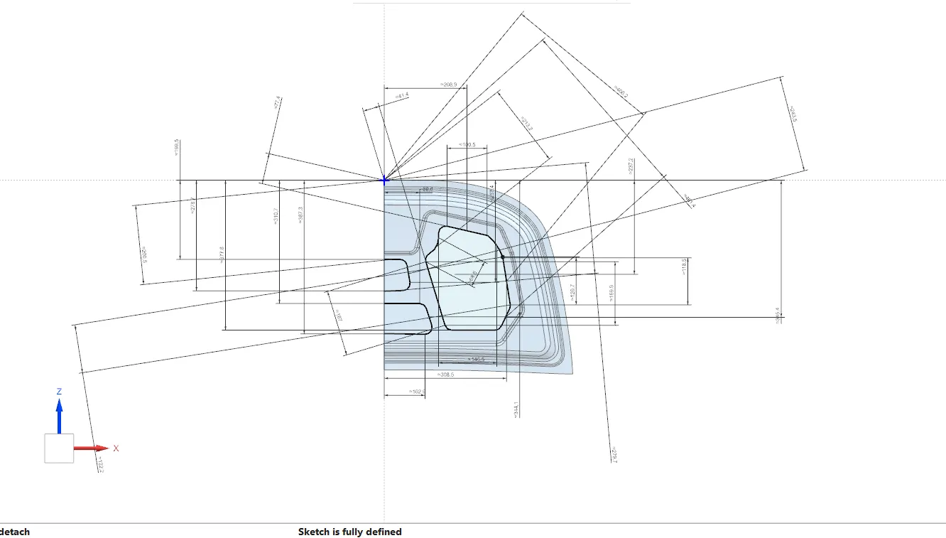
Created a fully defined sketch for the second emboss and projected over the inner panel face.
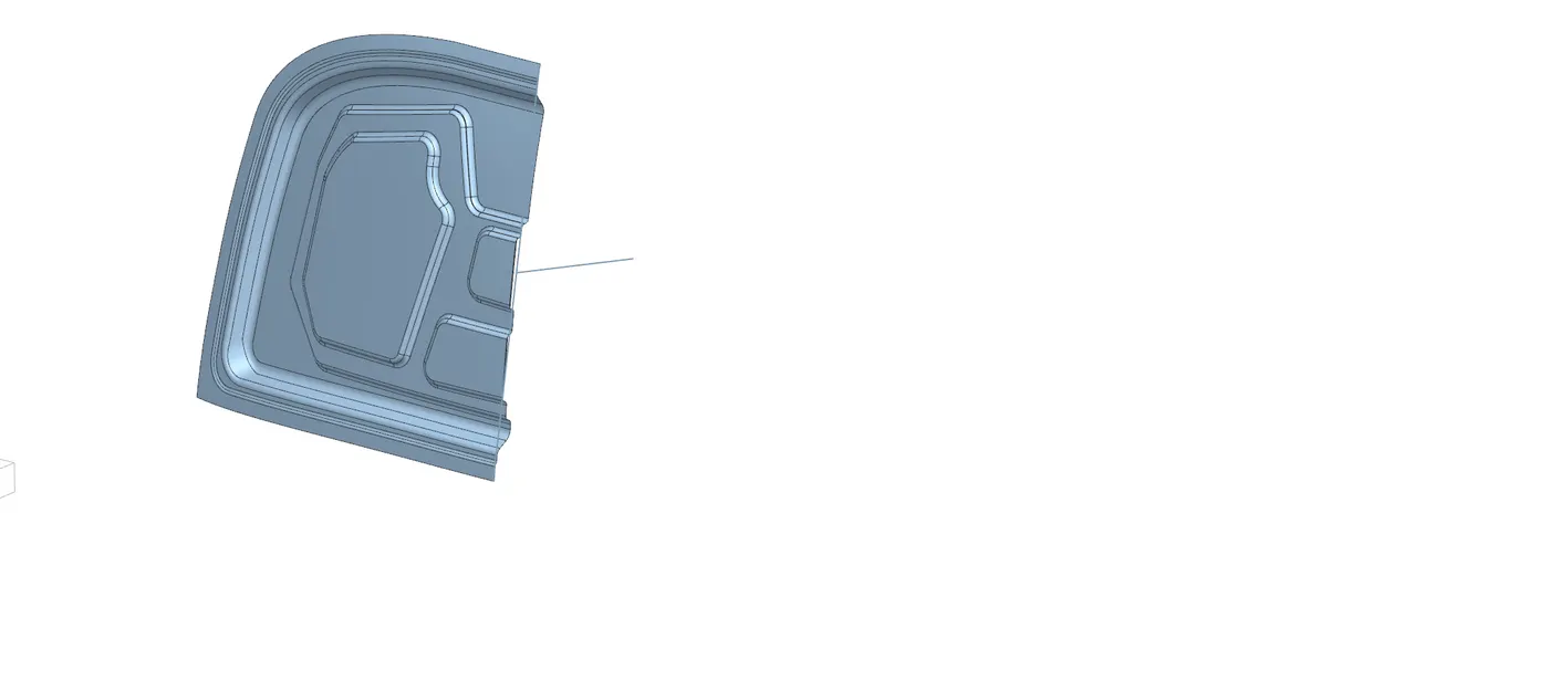
The second emboss is created with draft angle of 12mm and the depth of 8.5mm from the first embossed face. By giving the second emboss during embossing or stamping process it goes deeper and giving the increased draft will help during ejection of die. The depth of these two embosses are determined by the given mastersection data and after thickening the inner and outer panel there will be 5mm clearance between the inner and outer panel should has to be maintained for the mastic glue which helps in joining of inner panel with the outer panel.
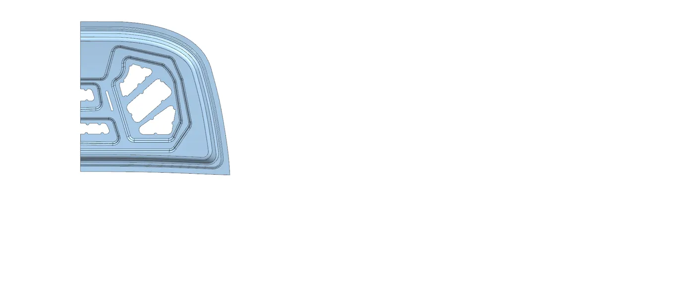
Mastic sealants are elastic compound that behaves like rubber and it is placed between the outer and inner panel. Initially it is in paste form but after the hot furnace bath it gets hardened thus joining the outer and inner panel.The mastic will helps to reduce the noise and vibrations it act as a good solution for NVH , The mastic cutout is created and the mastic will cover the distance of 80mm dia and it act as a sealant between the inner and outer panel. For the mastic , there should be a 5mm distance from the thickened inner panel to the thickened outer panel.
Hinge Mounting:-
For the hinge to be mounted on the inner panel we have to create a hinge mounting. The emboss is created for the hinge mounting with the help of datum plane which is created with respect to the parallel angle of the hood.
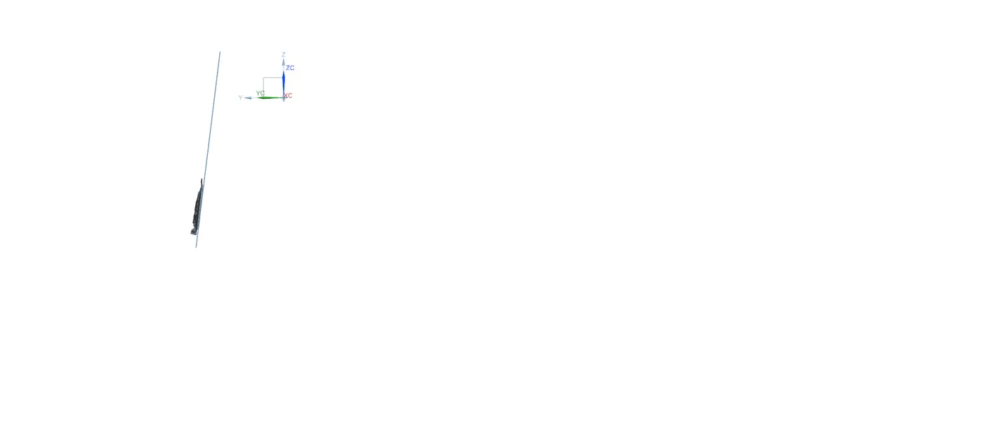
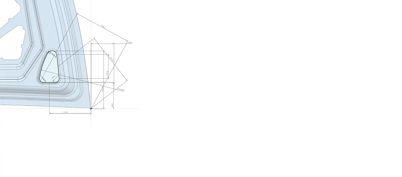
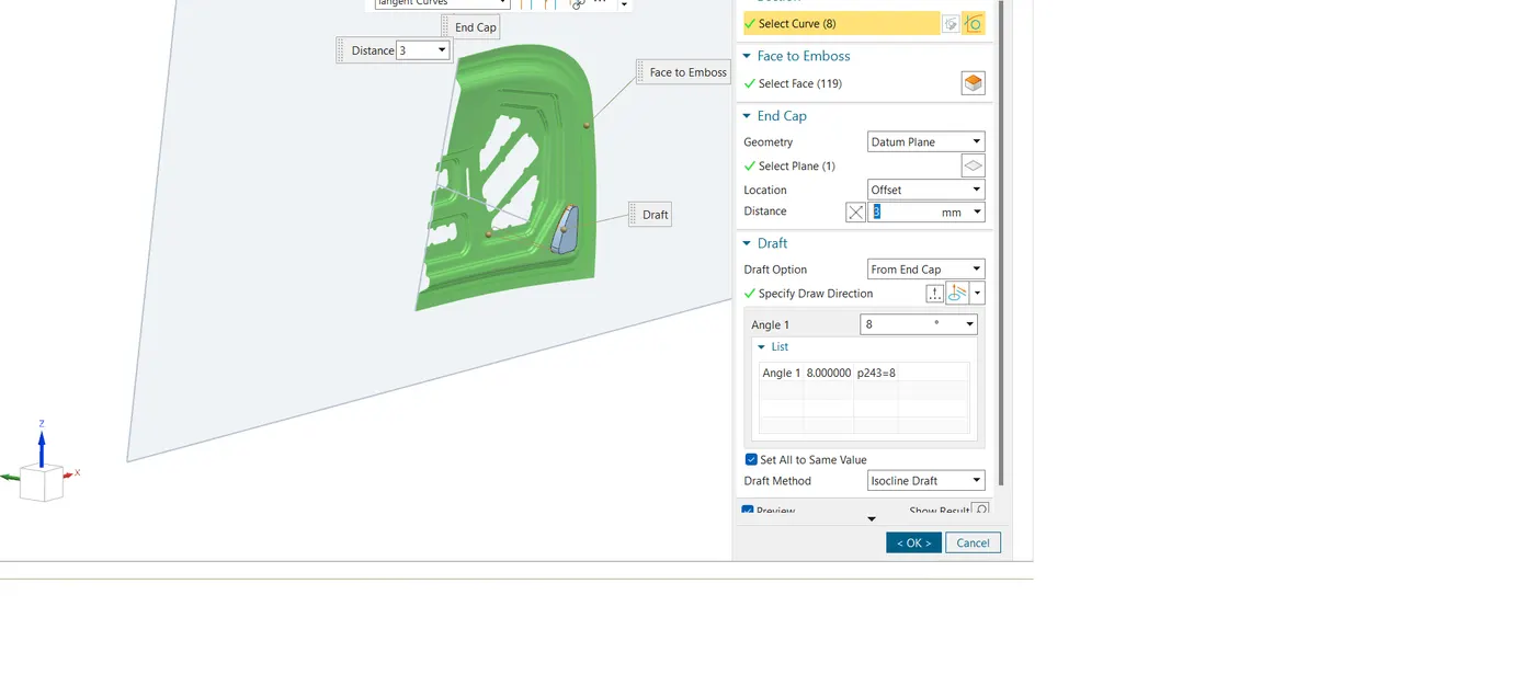
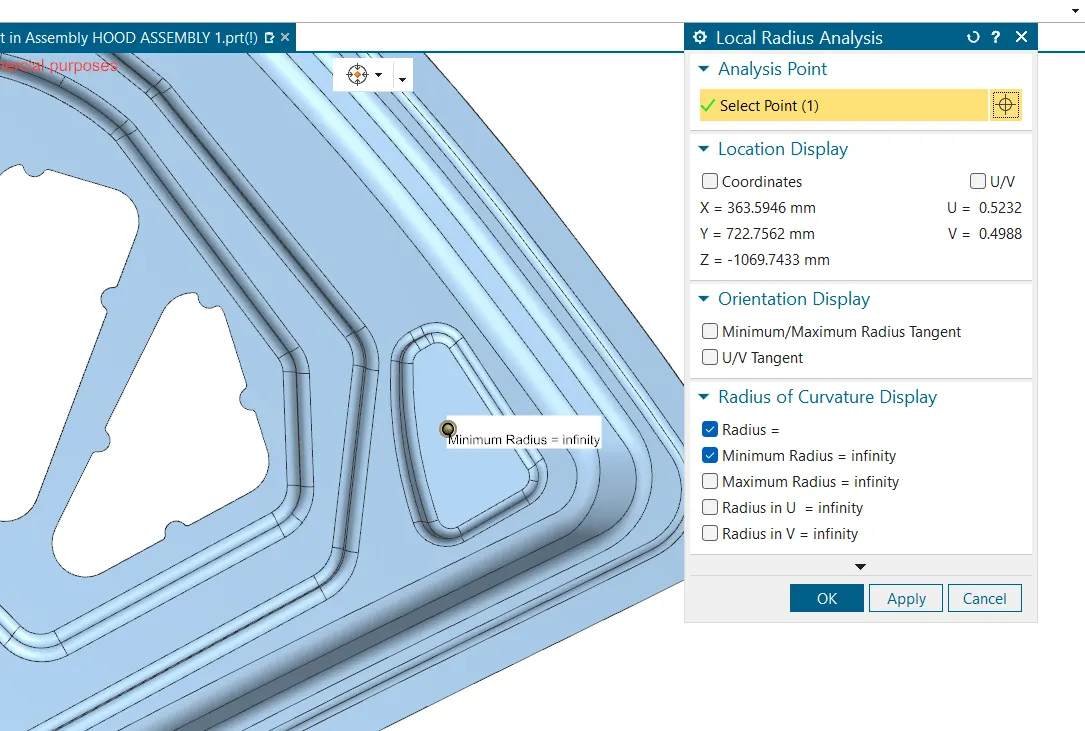
The use of datum plane is the mounting should be a flat face for the hinges so for that a datum is created with respect to the hood inner panel angle.Using the local radius analysis checked the mounting surface and it is indicated as a flat surface.
After created the mounting applied edge fillets and mirrored the part using mirror geometry command.
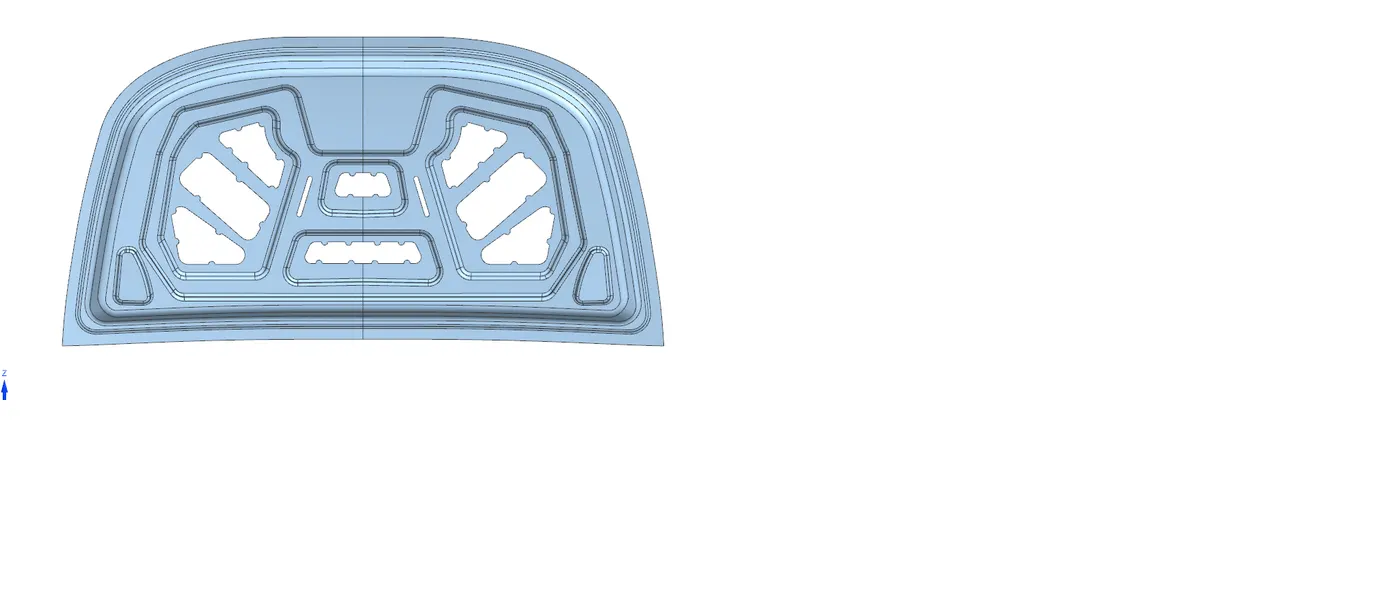
Sometimes after sew these two parts it may show some gaps between two parts to avoid that use extend sheet command to extend the centre portion that is the centre edge of the part and make a trim with the centre datum plane which is going to be the reference for mirror the part. Once done that you can also check by examine geometry command to analyse any gaps between the mirrored parts.
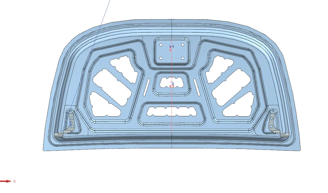
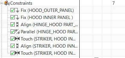
After created the mountings for hinges , we have to assemble it for the further trajectory arrangement for striker. So for assembly the hinge to the hinge mounting, we should give fix constrain for the inner panel and given the touch constrait with the hinge emboss and given a parallel constraint aling x axis.Once it is assembled in the positon, mirror the hinge using mirror assembly command to ensure the axis or plane for mirror the part and make it as associative so that the modifications in the parent part will be reflected to the mirror part.
Striker mounting:-
The striker is located inside the inner panel of the hood for that a mounting has to be created for that first we need to create a trajectory for the striker so that it can lock with the help of the latch in the engine compartment properly. For creating the trajectory we need to create an axis from the LHS hinge to the RHS hinge.
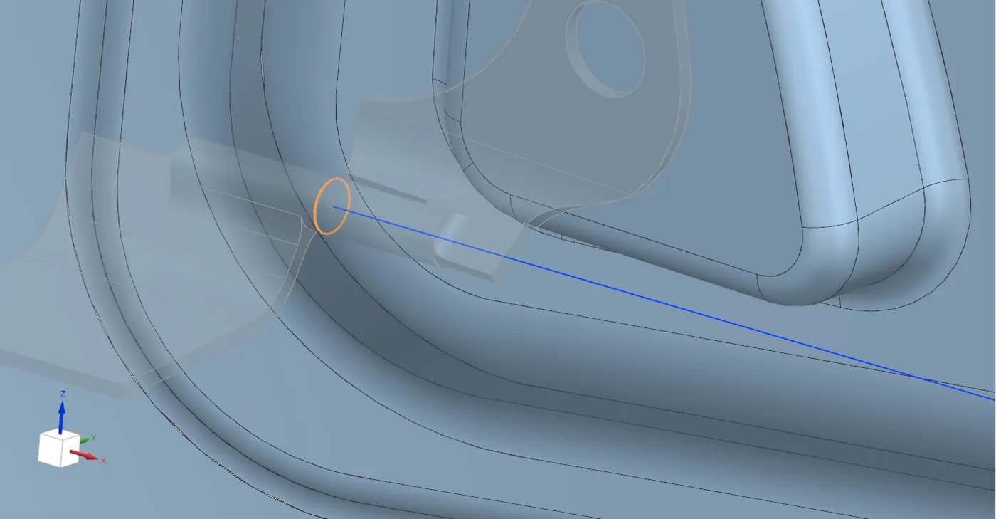
Using wave geometry linker extracted the circular curve from the both LHS & RHS hinge. Then created a point in the centre of the extracted circle.Then created a line from point to point.
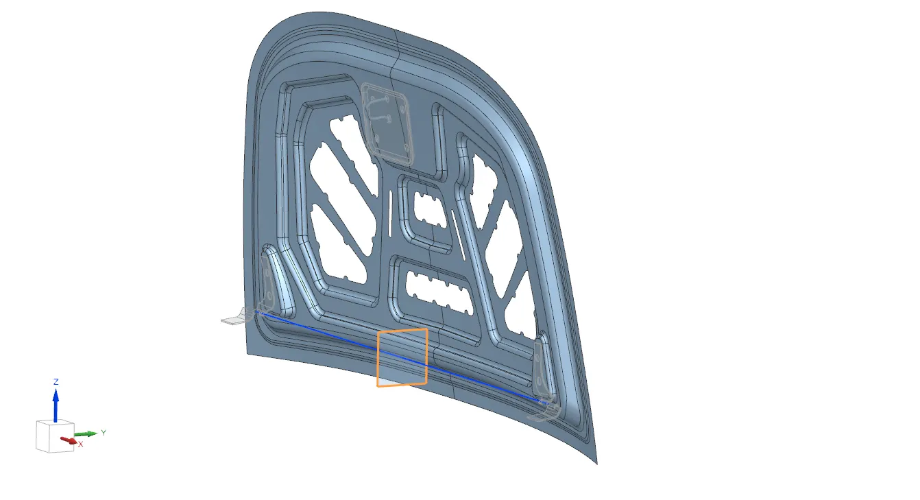
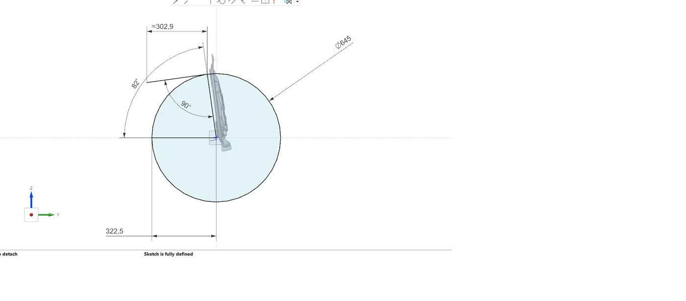
At the centre of the line created a datum plane for creating the trajectory of the striker. From the datum plane created a circle of dia 645mm and also created a line which is for reference ,horizontal to the circle. Also another line is created from the centre point to the circle in the in an angle of 82deg with respect to the horizontal reference line, then created the tangent line starting from the intersection point of the 82deg line end point with the circle and also made it tangent to the circle , Now it is the tragectory of the striker with respect to the hood.
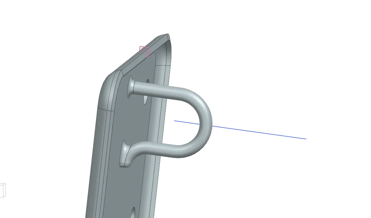
Datum plane is created at the centre of the striker and created a horizontal line in the centre of the hook. The line created in the hook of the striker (starting point) is assembled to the end point of the tangent line in the hood inner panel by applying touch constraint. Then again applied touch constraint to the striker line with the tangent line and aligned it with datum plane created for the trajectory to the datum plane created in the striker hook. After giving these constraints we have to check the position of the striker and adjust it by reducing or increasing the diameter of the circle.
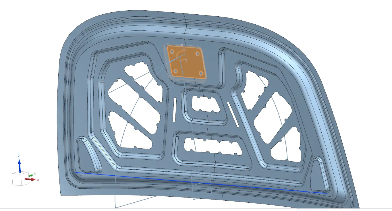
Extracted the back surface of the striker by wave geometry linker to create the mountings, after that extended the surface because while giving fillets chances of size of the mounting will be less for the striker.
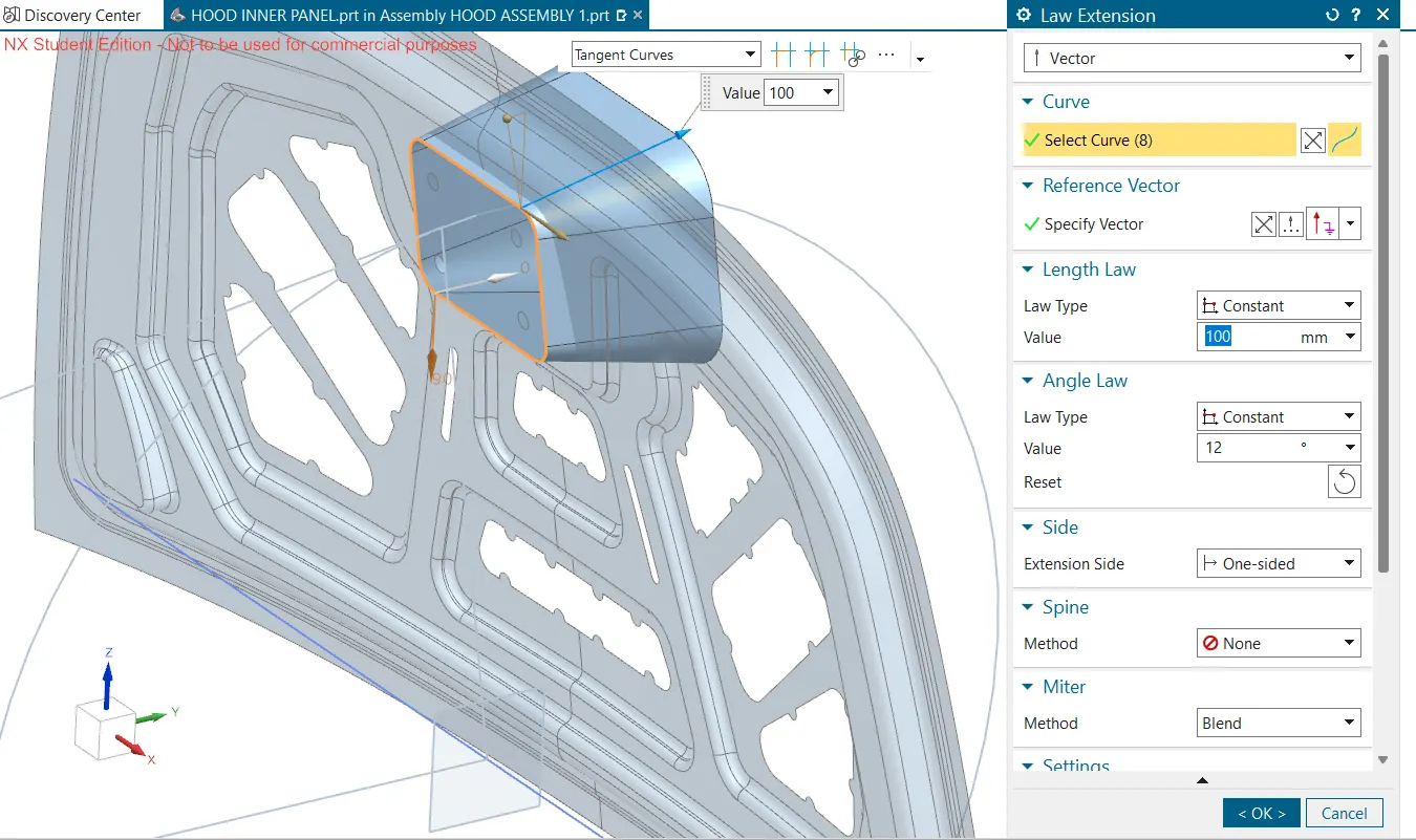
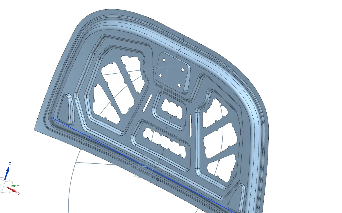
Then using trim and extend command trimmed the unwanted portions of the law extensions and created the mounting for the striker. Then applied edge fillets for the mounting and checked the mounting is large enough to support the stricker and edge to edge clearance of the fillet also checked. The mounting depth can be adjusted by adusting the angle of the stricker trajectory.
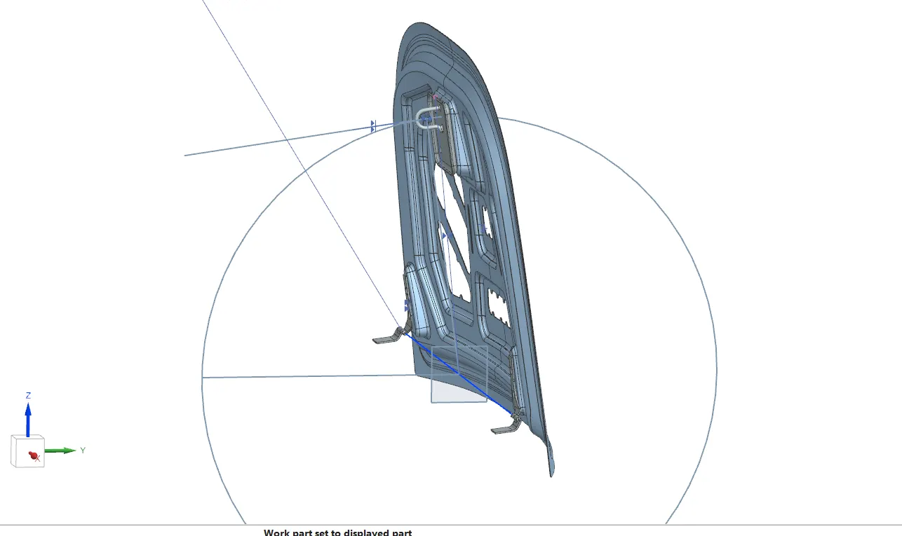
After giving the assembly constraints check the mountings of stricker and hinges which should be properly contact with the mounting surface.
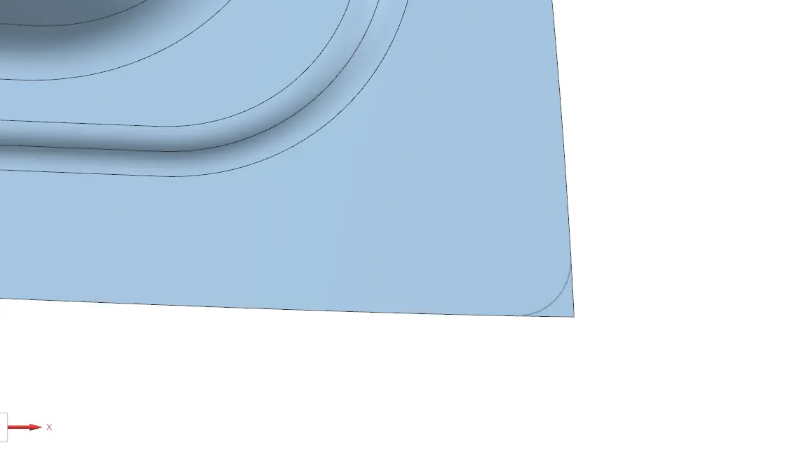
Created the bridge curve on both sides and trimmed the sharp corners of the inner panel to avoid interfernce with the outer panel during hemming process.
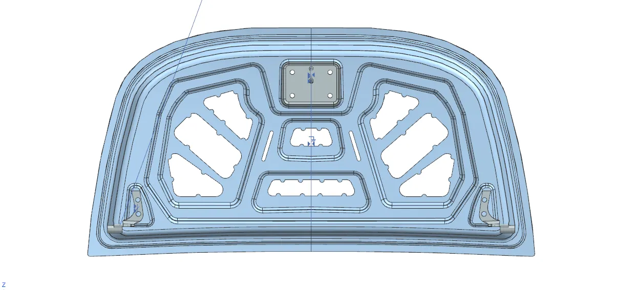
After that trim thickened the innerpanel for 0.75mm as mentioned in the challenge.
Joining process:-
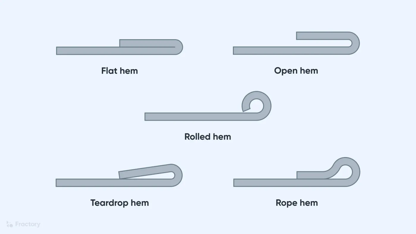
Hems are folds to the edge of a part to create a rounded, safe edge. Hems may be open, flat, or tear-dropped, and tolerances depend on the hem’s radius, material thickness, and features near the hem. The process of creating hems is called hemming.
Flat (or) Closed hem:-
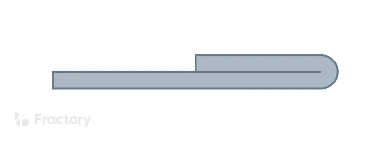 In a flat or closed hem, the part of the edge that bends sits completely flush over the rest of the metal sheet. The angle between the returning flange and the sheet metal is 180 degrees. The inside radius is zero and thus, there is no gap between the returning flange and the metal sheet.
Closed hems require a lot more power and tonnage from the presses than open or teardrop hems and it is also not advised for metal sheets that are over 2-3mm in thickness since the sheets are likely to fracture.
Open hem:-
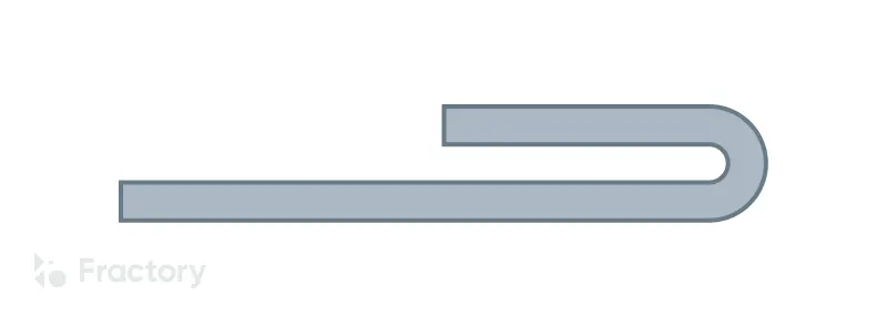 In an open hem, the returning flange is folded over the sheet metal but there remains an air pocket between the two. The bend angle in this hem type is also 180 degrees.
Teardrop hem:- 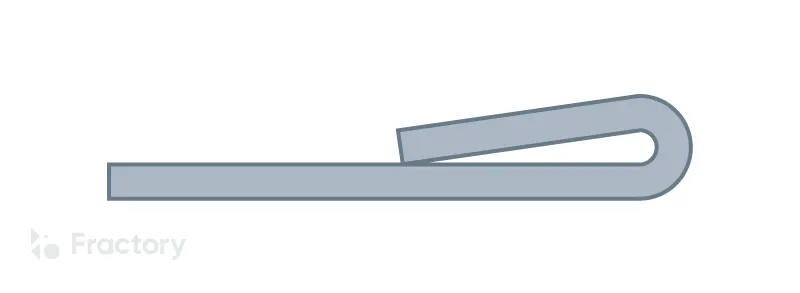 In a teardrop hem, the returning flange is bent beyond 180 degrees. The resulting shape resembles a teardrop.It is perfect for materials that do not have the required ductility to provide closed hems. Teardrop hems are used for fragile materials such as aluminium.
Rope hem:-
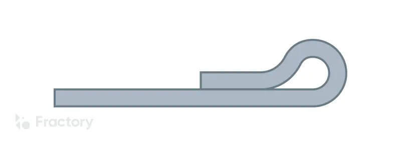 A rope hem has a returning flange at a bent of more than 180 degrees. Once the hem achieves the shape of an open hem, the returning flange is pressed onto the part surface through a flattening die.The edge is bent in shape similar to an open hem and then the second piece to be connected is inserted into the gap between the metal sheet and the returning flange. Further pressing takes place making the second parts sit flush between the metal sheet and the returning flange and create a joint.
Rolled hem:-
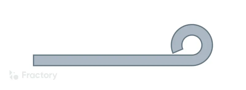
In a rolled hem, the bent portion of the sheet metal is tucked back into itself. This creates smooth round edges all around for holding the part from the hemmed edges. This process is also commonly referred to as curling.
Hemming process:-
- Die hemming process
- Roller hemming process(Manual roller hemming, Robotic roller hemming)
Hemming is a technology used by the automotive industry to join inner and outer closure panels together (hoods, doors, tailgates, etc). It is the process of bending/folding the flange of the outer panel over the inner one.
Here we will do the open hem and most of the OEM's uses robotic roller hemming.
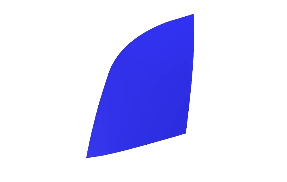
Trimmed the given class A for creating the hemming on one side and later will do the mirror geometry. Then made a cut in the corner portion of the outer panel with 8mm of bridge curve which is already done in the inner panel.
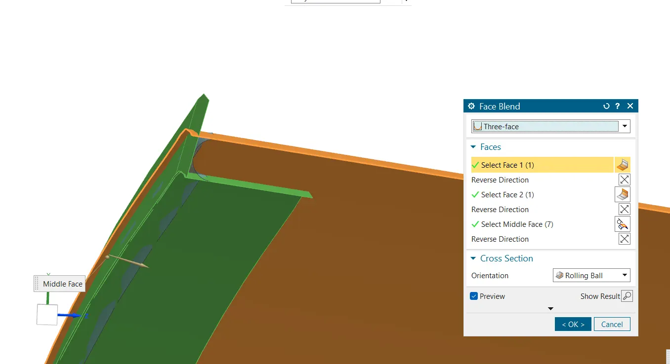
After that offseted the outer panel to the distance of 2.65mm with respect to the above mentioned values for hemming flange creation. Created a offset face in curve for 7mm for the hemming and created another offset face in curve for 0.1mm to create the hemming bend surface, law extension is created for aroung 8mm with 97deg which has to intersect with the outer panel surface and applied 3 face blend for the hemming curve of the outer panel.
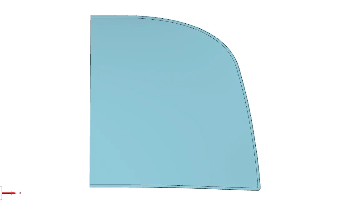
The hemming should be like this before giving relief in the corners.
The above image is an example for rolller hemming.
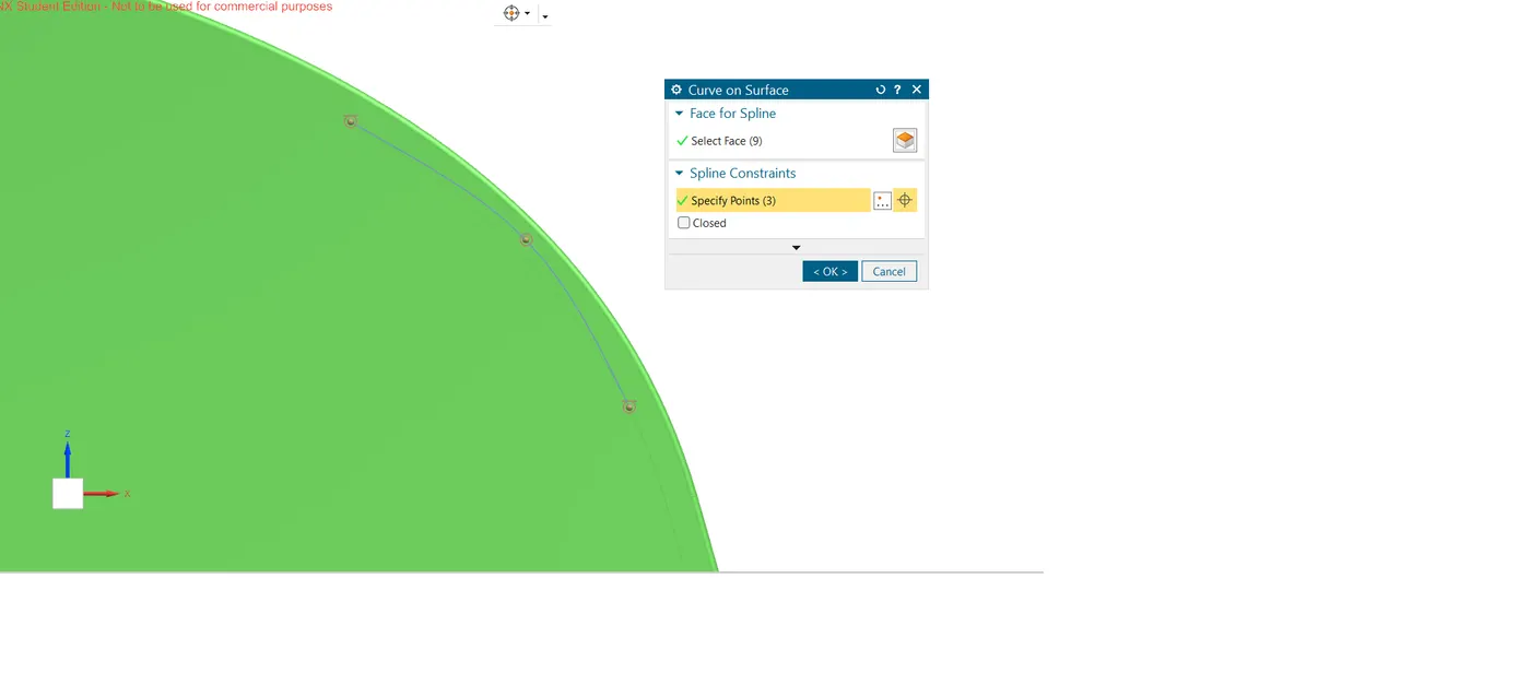
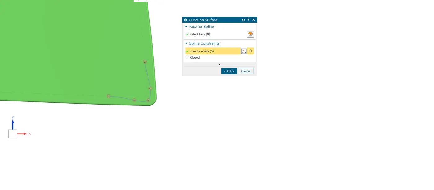
The relief has to be created over the corners of the outerpanel which is to avoid overlapping of sheets during roller hemming.
Both the front and rear relief has to be maintained 3mm length as per the design guidliness.
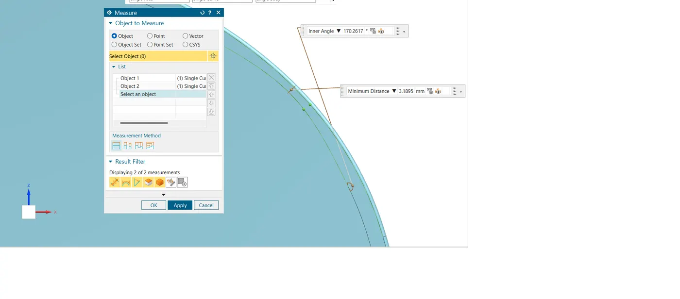
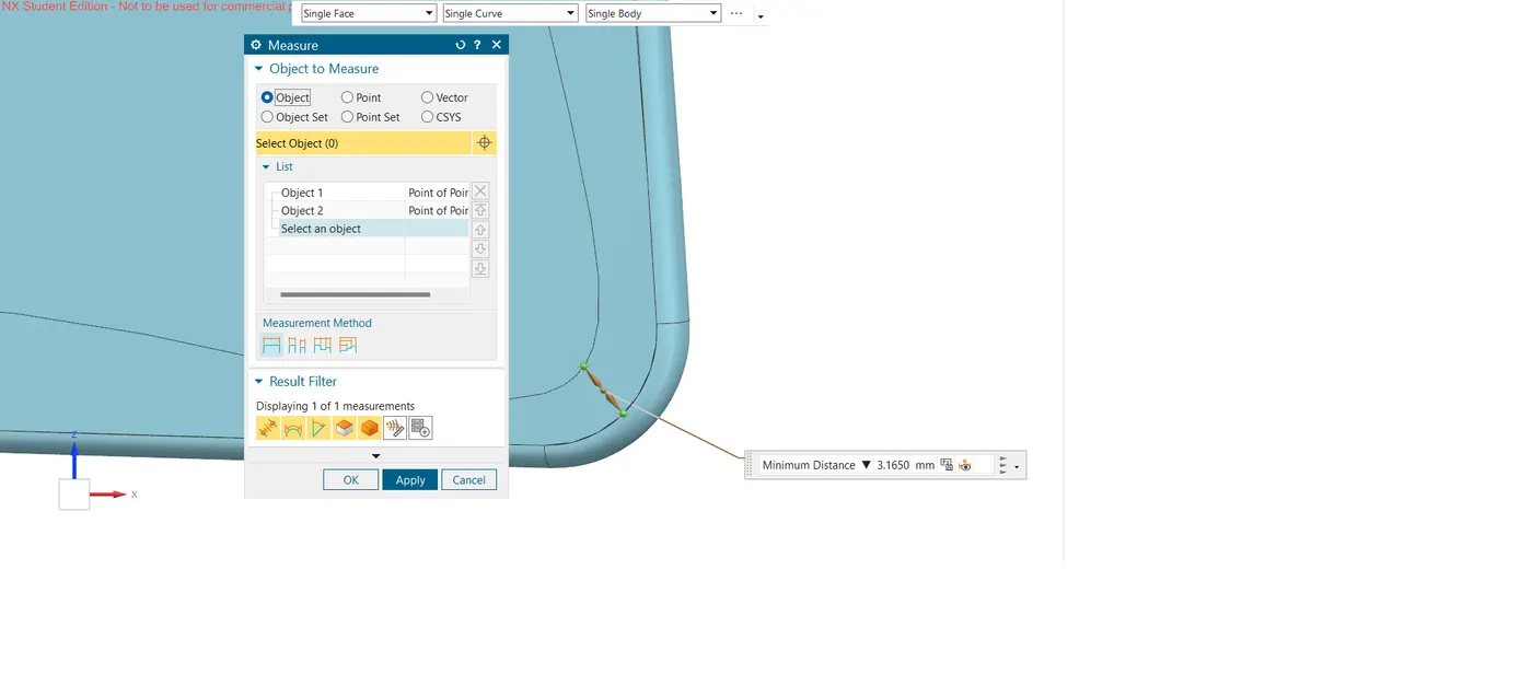
Once the hemming relief is provided then mirrored the hood outer panel and sew both the parts.
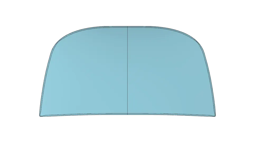
Applied thicken command of 0.75mm mentioned in the challenge.
After the hemming process the values to be checked whether it is matching the given data as per the guideliness.
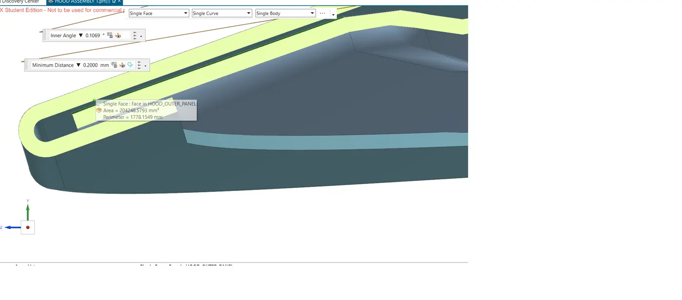
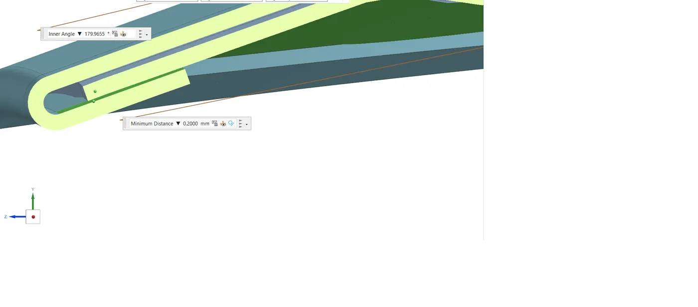
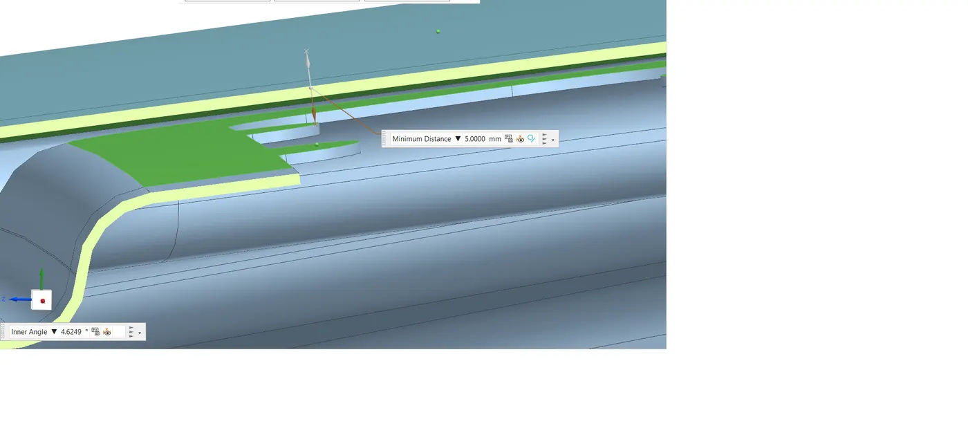
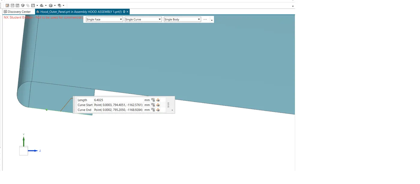
The 0.2mm gap between the inner panel and hood in the hemming area is to fill with the hem glue for the assembly of outer and inner panel and also it'll reduce noise,vibration.
Draft analysis:-
After thickenening the hood inner panel draft analysis is done to check the manufacturibility of the part.
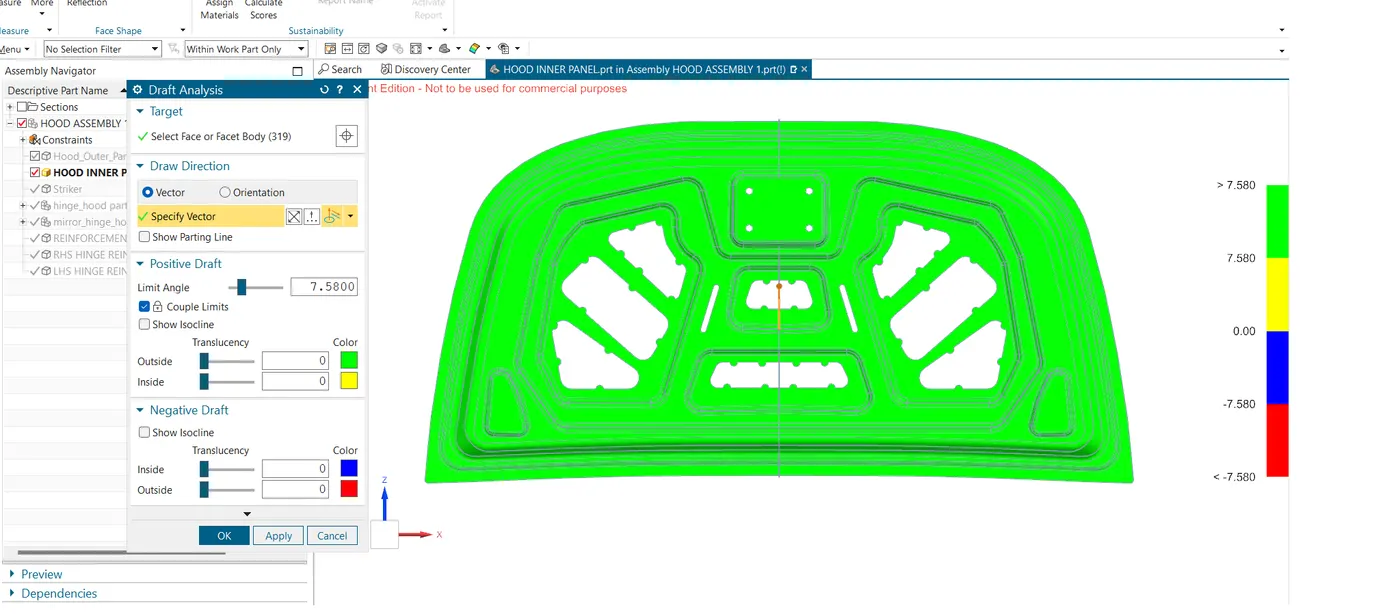
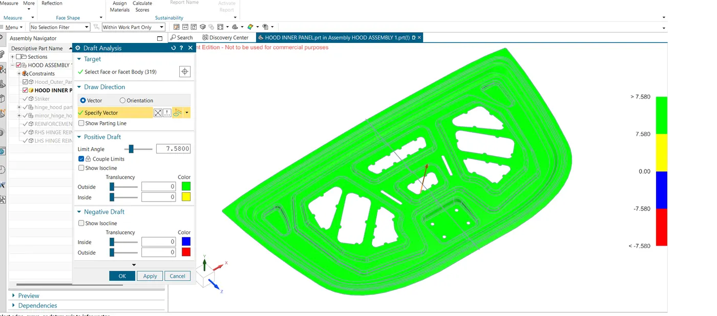
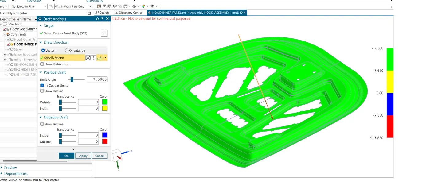
The minimum value of the draft is 7deg as per the industry standard and deeper the sheetmetal to be embossed or deep drawn ,the draft should be higher for tooling feasibility.
Deep Drawing:-
In the deep drawing process, the sheet metal is radially drawn into the die cavity by the mechanical action of the punch in this process the work piece is put onto the die and the blank holder is then introduced on the top of the workpiece, which is not deformed by punch.
Reinforcements for Hinge mountings and Striker mountings:-
To increase the strength of the mountings the reinforcement is created with the thickness 1.5mm as mentioned in the challenge. The stricker and hinges will have the enough support with the help of the reinforcements.

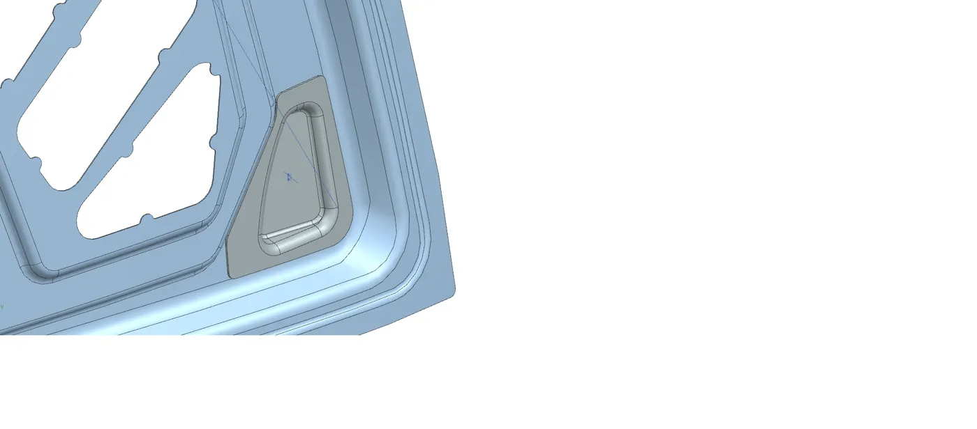
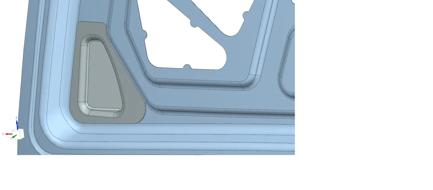
The above images are the reinforcements for striker and hinges.
Due to the memory constraint i am not able to upload the zip file in the file uploading box. so as per the discussion with tse, i uploaded it in google drive and pasted the zip file accessing link below .
Google drive link:-
https://drive.google.com/drive/folders/161NVmRfe9XidifbvlLaO4ptNDLxaLjR6?usp=sharing