Hood design-Week 2
Created "Hood Assembly Final"
Imported Hood outer panel. Trimmed by YC-ZC plane.
A) Hood Inner Panel
Created new component in Hood assembly Final "Hood Inner Panel". Extracted trimmed outer panel using WAVE geometry linker and created 0mm offset for working surface. Created tooling axis.
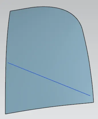
a)Master Section
Created offset in face of 1.7mm and trimmed the sheet as per master section. Given best fit for sharp corners.
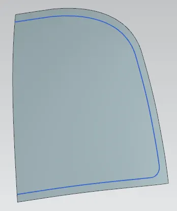
Followed same steps for next 4mm and 25mm offset and trimmed the sheet.
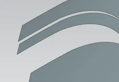
Used through curves to created surface in gaps of 3 offsets. Given blends of 6mm, 6mm, 10mm and 15mm respectively.
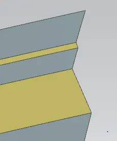
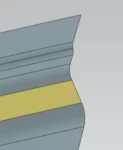
Minimum distance between inner and outer panel should be 5mm for mastic application. So secondary emboss provided of 10mm and next functional embosses are provided offset of 8.5mm.
b)Secondary Emboss
Created curves for secondary emboss using Offset in face, Intersection Curve, Bridge curve and Composite curve. By analyzing dimensions of Striker and Hinge assembly, areas provided for remaining embosses.
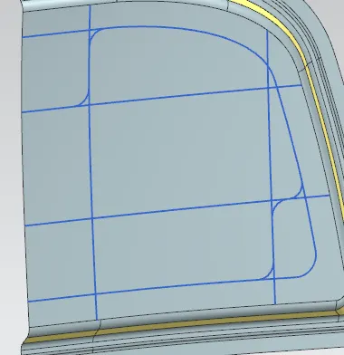
Provided offset of 8.5mm for face and created law extension by using vector as tooling axis. Then used trim and extend and created corner (Emboss). Provided appropriate blend of 4mm.
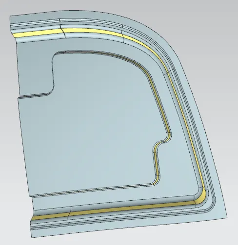
c) Functional emboss
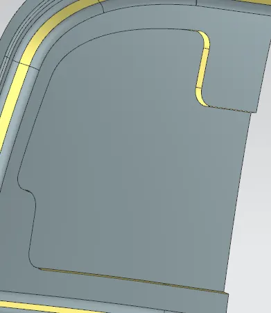
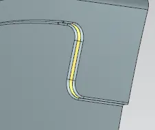
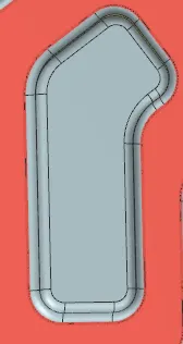
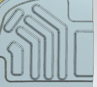
Created sketch for functional emboss by using Offset in face, intersection curve, bridge curve, composite curve and projected on secondary emboss. The pattern is considered to resist the frontal crash damage and dissipate the force towards the piller and side body.
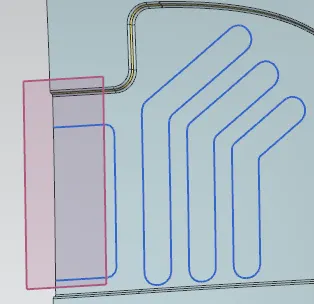
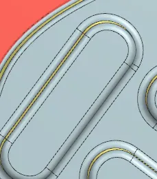
Created law extension with 7 degree draft and offset the single face and used trim and extend to create embosses. Provided fillets within sharp corners.
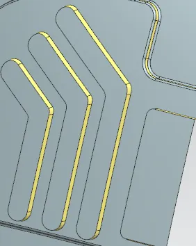
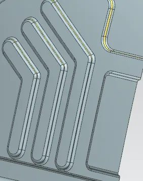
Created another embosses for remaining areas.
d) Cutouts
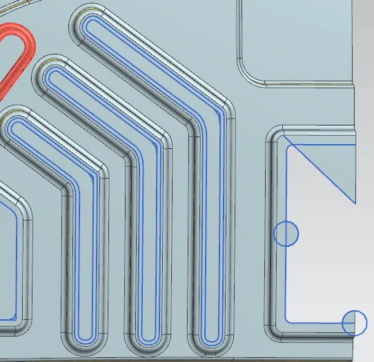
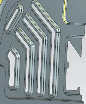
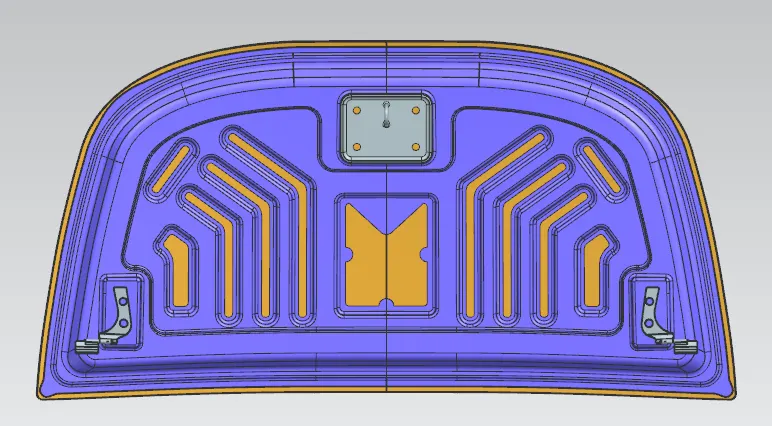
Created sketch like in the image attached below by using offset in face, bridge curve and trimmed the sheet accordingly. Provided semi circular areas for mastic.\
e) Hinge emboss
Created plane using 3 points and line of 78mm length and extruded symmetrically.
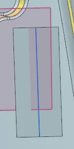
Created bridge curves and trimmed the sheet for smoothness. Created law extension and used trim and extend to form the emboss. Provided proper blends for all sharp corners.
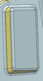
Created mirror geometry for the surface and mirrored with ZC-YC plane and sewed.
f) Corrections
After examining geometry, intersection between faces and gaps are evident. So went back before mirroring the surface, extended the sheet and trimmed with ZC-YC plane and repeated the procedure. Trimmed the sharp corners with bridge curve and trim sheet.
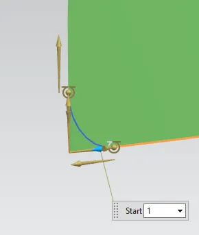
Offset in face by 2mm at outermost edges of inner panel and trimmed the sheet to avoid the intersection between thickens of inner and outer panel.
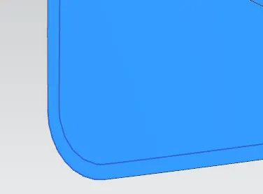
g) Striker emboss
Extracted the mounting surface of striker using WAVE linker geometry and extended the sheet by 8mm.
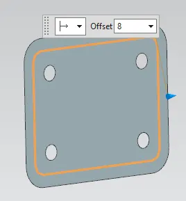
Created the law extension and trimmed using law extension. Created the draft of 7 degree with tooling axis and provided the blends
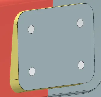
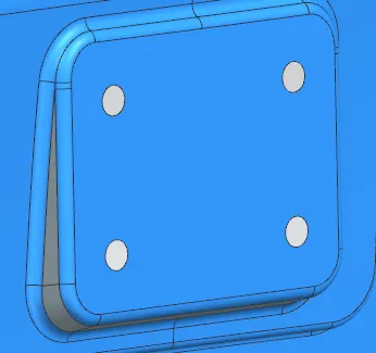
h) Striker mounting
Interted the hinge assembly to main assembly. Created new CSYS on center axis of hinge assembly and provided touch and parellel constraints to rest it on hinge emboss properly.
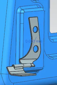
Mirrored the assembly containing 2 models wrt ZC-YC plane to rest another hinge on another emboss.
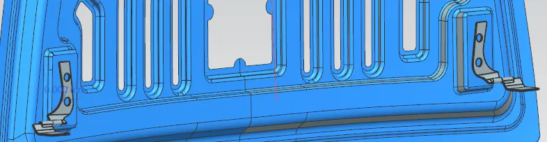
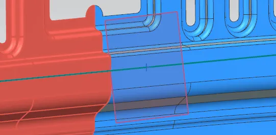
Extraced the curves from both hinges and created their arc center. Same process followed for another circle. Line is drawn from both center points. Created center point of the line and plane at center.
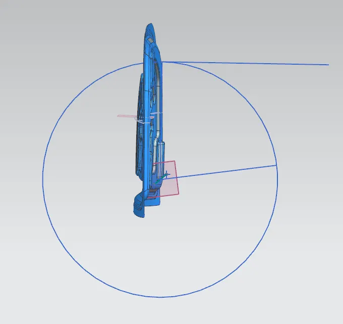
Created circle of 310mm radius and drawn one horizontal line towards surface. Created another line wrt previous line by 82 degree and next line drawn from same end point of line which is tangent to the circle.
Finally thickened the sheet by 0.75mm
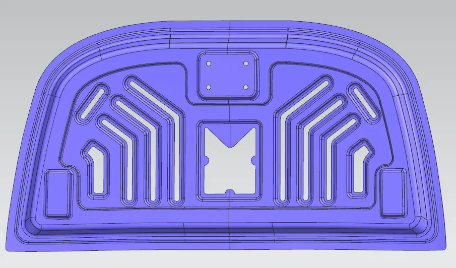
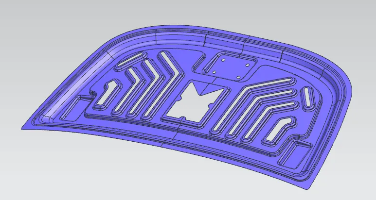
B) Striker
Created new CSYS in front of striker. Created intersection curve for mounting face and extracted the arc center of circle. Created a normal line of random thickness.
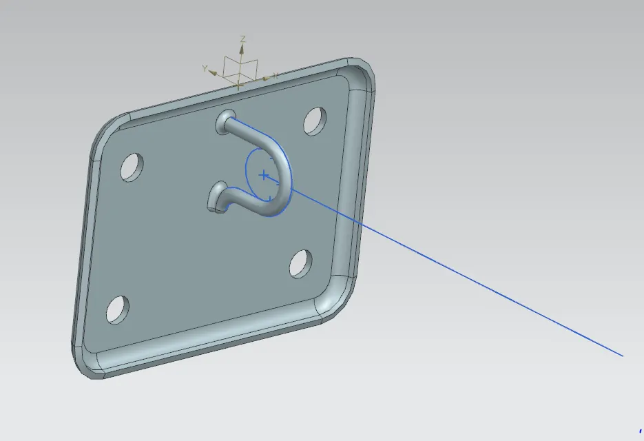
Mounted the striker on feasible position for striker emboss using constraints. Provided constraints of touch and parellel for referance geometry to match the normal line, mid point and ZC-YC plane.Created emboss using extracted face of striker inside Hood inner panel.
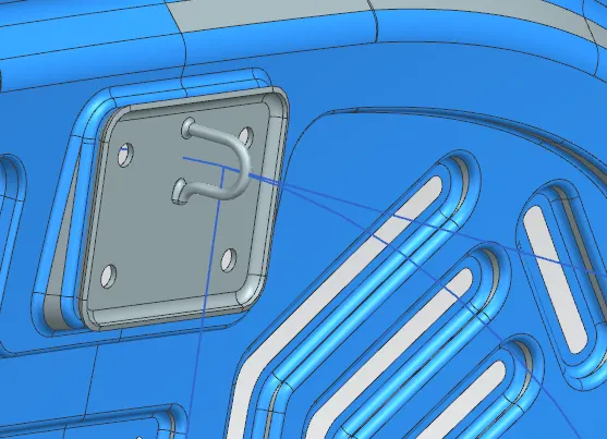
C) Hood Outer Panel
Created bridge curve and trimmed the outer sharp cornar of outer panel and inner panel as well.
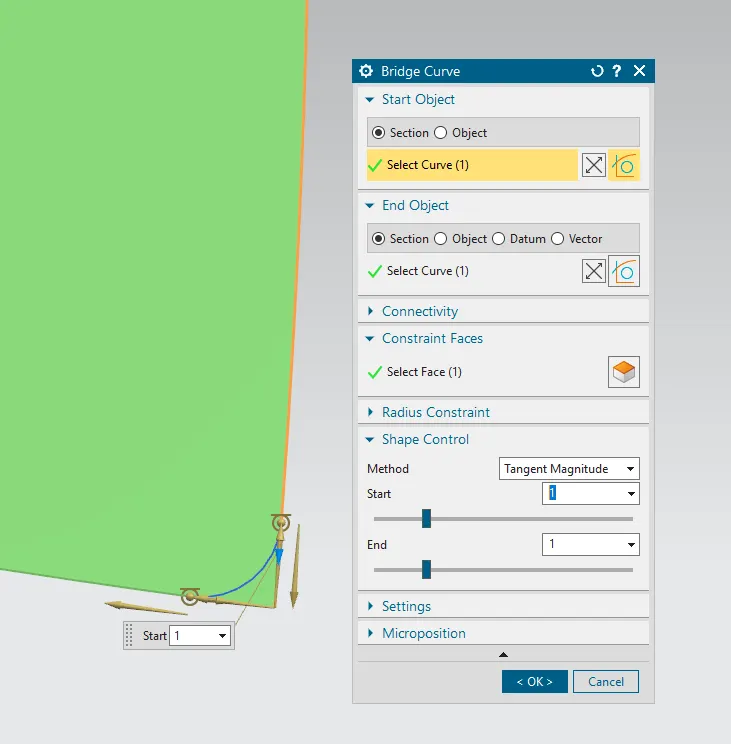
Created tooling axis using line and points.
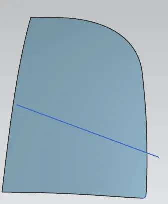
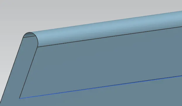
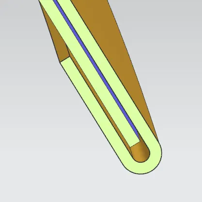
Offsetting the working surface by 2.65mm towards inner panel for hemming surface creation.
0.75+0.2+0.75+0.2+0.75=2.65
Trimmed the surface by offset in face by 8mm and created though curves and 3 face blend
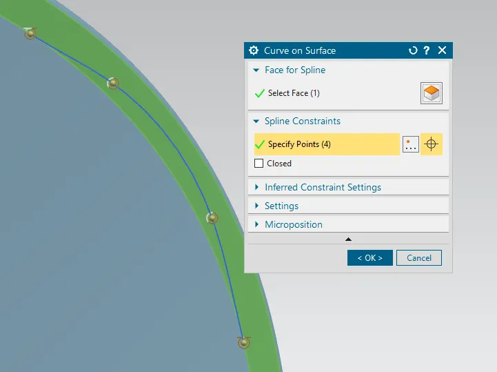
Created curve on face and trimmed the sheet where stress concentration becomes more at sheet. This is called as relief areas.
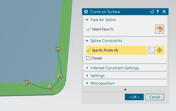
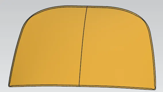
Finally mirrored the surface and sewed to form the outer panel
D) Reinforcement
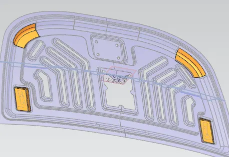
Created refinforcement for critical areas by extracting the faces and thickening by 1.5mm.
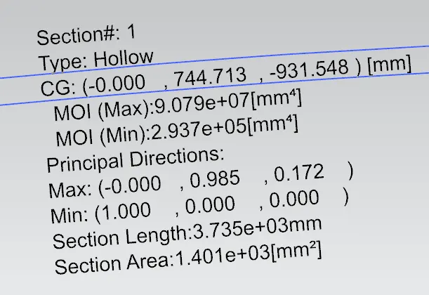
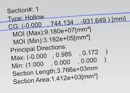
E)Section modulus
F) Hemming
All files are not sent due to sharing limit (20mb)