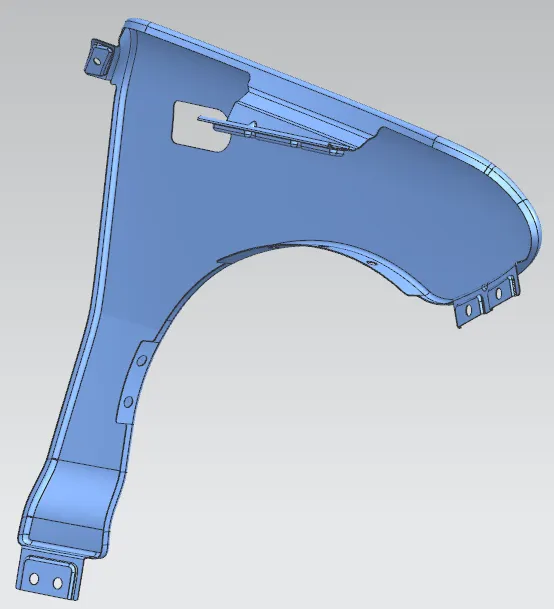
Fender Design
A) Correction
Examined the Class A and found the issue with surface
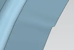
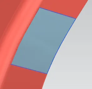
Fixed the patch by trimming certain area and recreated by through curve mesh using premade cross curves.
B) Master section
Offset the curves shown in below image by 5mm
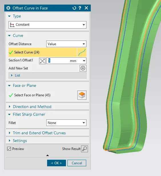
Provided clearance of 150mm from each side as shown in master section and created 2 datum planes
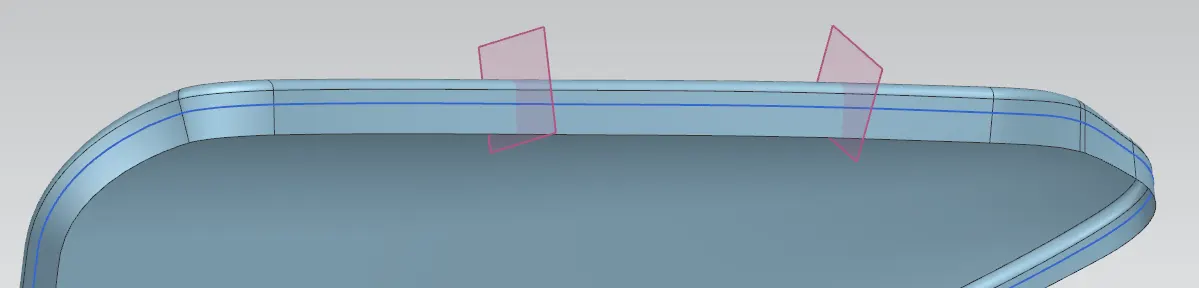
Created first law extension and trimmed the sheet by bridge curve at sharp corner
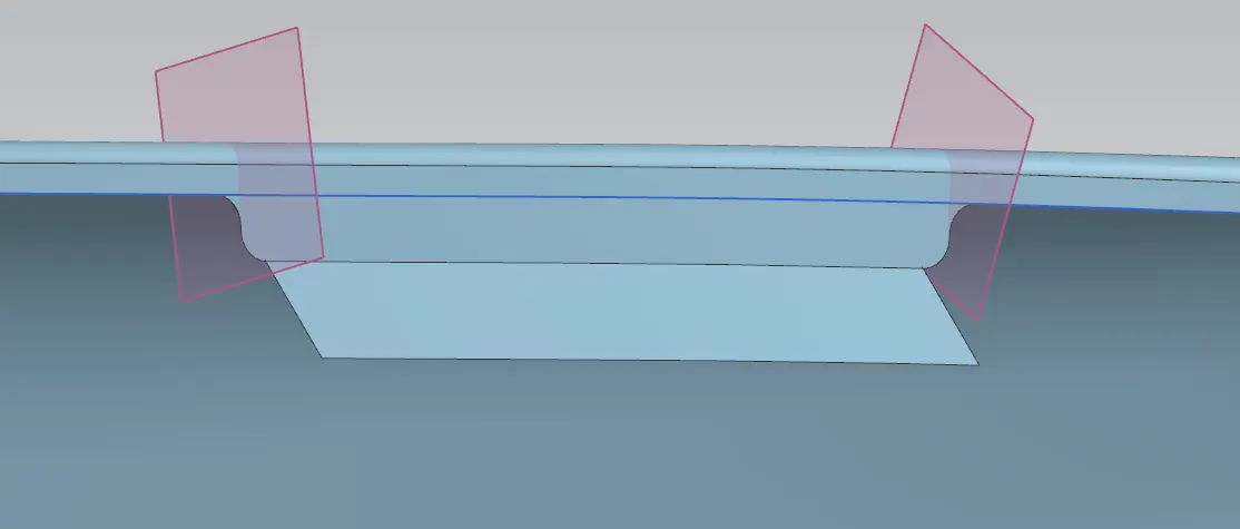
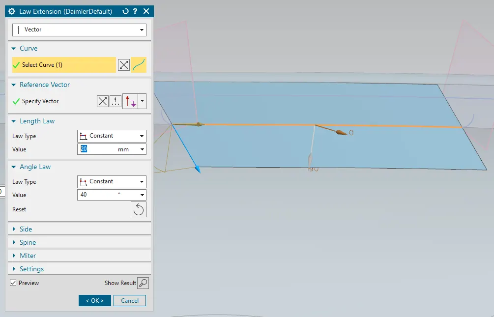
Providing offset of single surface and trim it by extended law extension. Provided fillets as per master section.
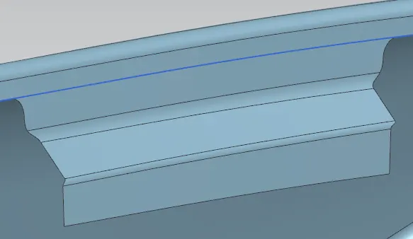
Created 2 datum planes of 35mm distance for maximum distance verification of drip area mounting. Extended the sheet for craeting next law extension
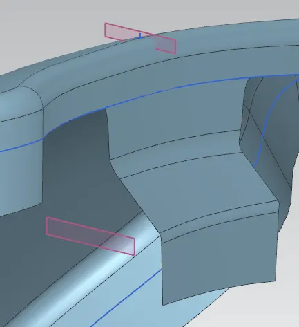
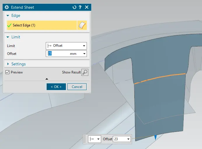
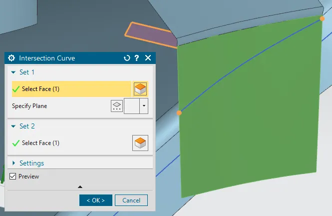
Emboss requires flat surface and holes. Created intersection curve of 35mm offset plane and law extension created within this curve.
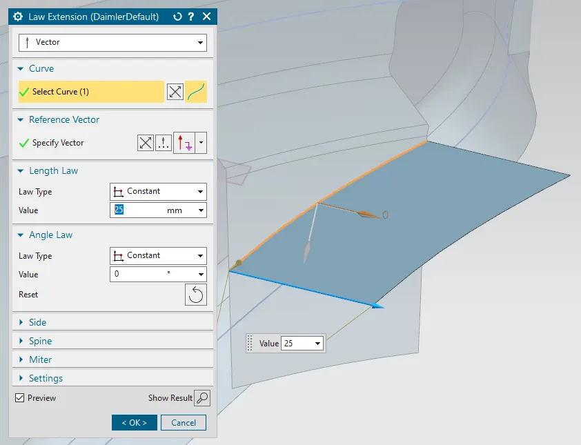
Created Dart of 5mm depth for increasing the strength and reduce bend of mounting. Provided blends
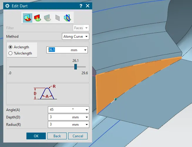
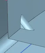
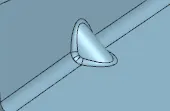
Found next distances by trigonomety as required angles and sizes are given. First length is found as 3mm and next is 0.53mm using tan45 and tan15
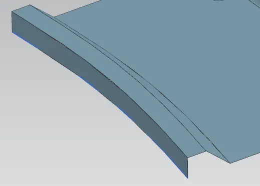
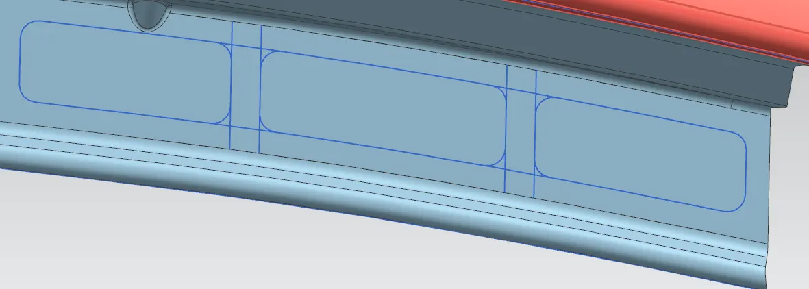
Created sketch by offset in face, bridge curve and composite curve
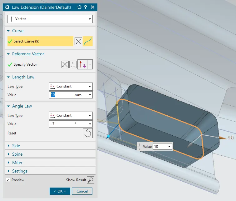
Provided emboss law extension and 7 degree of draft angle.
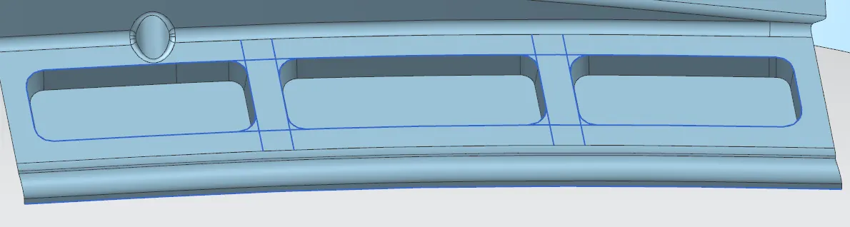
Finally trimmed the law extensions and emboss formed, blends provided.
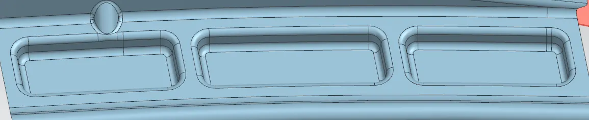
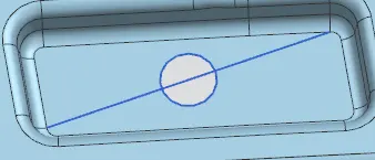
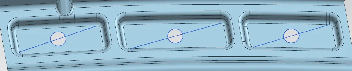
Created holes by drawing the lines and creating arcs on their midpoints of 4mm radius and trimmed them.
C) A Piller mounting
Trimmed the nearby area for A piller mounting
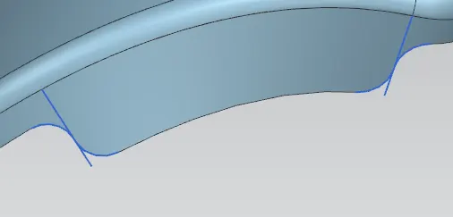
Created law extension for mounting surface
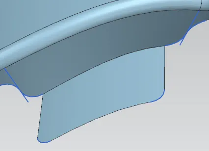
Created a datum plane by 3 points and created a line on it. Extruded by symmetric value and offset the face by 2mm for emboss depth.
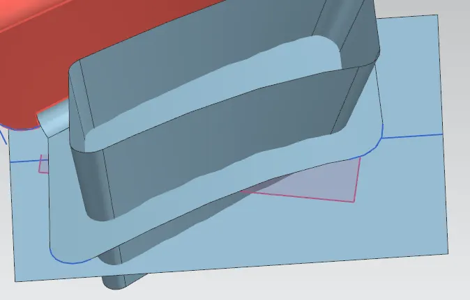
Finally trimmed and provided blends
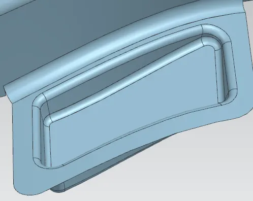
Provided a 4mm radius hole and trimmed. An unwanted extended sheet is found so it gets trimmed by creating bridge curve

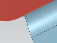
D) Bumper mounting
Trimmed the nearby area for Bumper mounting regions
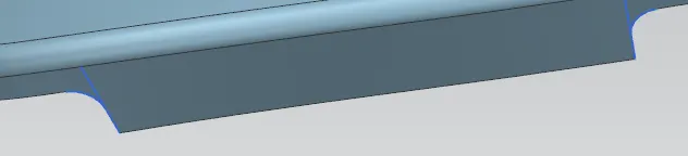
Created the law extension for emboss forming and bumper rest
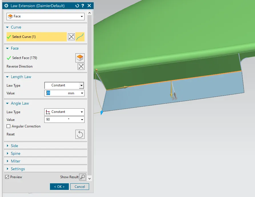
Created trim and entend also provided a dart for removing bending
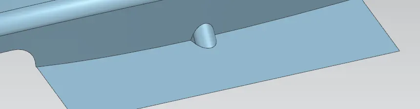
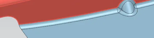
Created sketch using offset in face and bridge curve
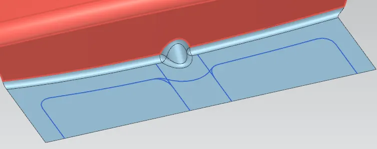
Created the law extension for emboss
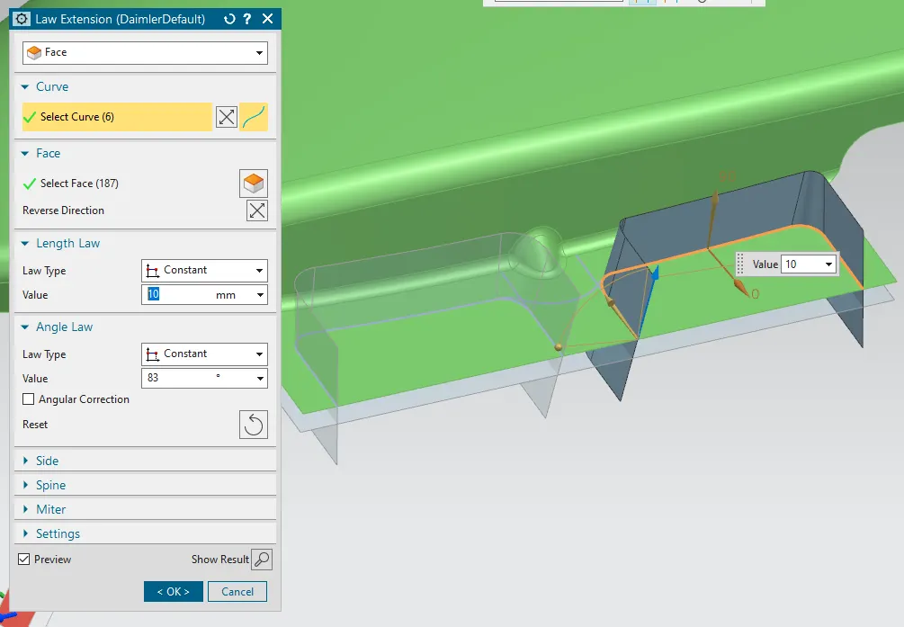
Finally trimmed and blends provided
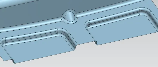
Provided 4mm radius hole and trimmed sharp corners
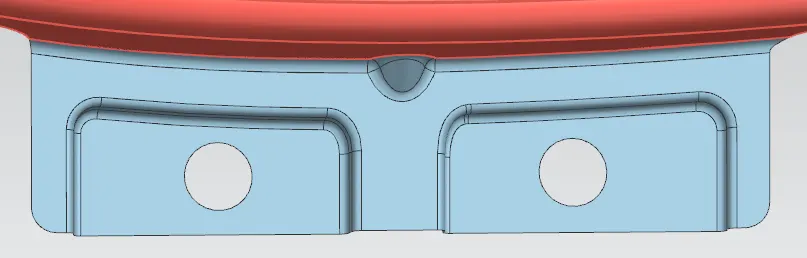
E) Sill mounting
Trimmed the around area of sill and created the surface with a plane and line and extruded it by symmetric value. Created law extension
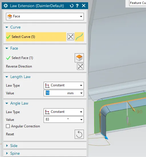
Finally trimmed the surfaces and provided fillets. 4mm radius hole is created and trimmed the sharp corners as well.
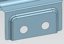
F) Wheel arch mounting
Created trimmed section around wheel arch mounting. Created a bridge curve of G0 continuity along the center of face. placed the points and circles of 4mm radius. trimmed the face by these holes for moun the wheel arch

G) Turn signal mounting
Created a sketch on distance plane and projected on surface with vector. trimmed the surface for turn signal mounting
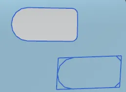
Finally provided thickness of 0.75mm from inside and hidden the curves, datums and sheet.
H) Final Body