Hood design-Week 2
Hood design
Aim: To Design Hood outer panel, inner panel and the necessary reinforcements by following the Master section with the design parameter
Introduction: Hood is the main component of a car at the front portion. It is used to decorate the car and add a luxurious look. The shape of the Hood is made aerodynamic in order to minimize the air effect. Hood is generally used to access the parts easily such as radiator, engine and many other parts. A car hood, also referred to as a bonnet in some other countries, is the hinged cover that rests over the engine of a front-engine vehicle. Its purpose is to provide access to the engine for repair and maintenance. A concealed latch is typically used to hold down the hood. On vehicles with an aftermarket hood and on race cars, hood pins may be used to hold down the car hood. Hoods sometimes also contain a hood scoop, wiper jets, power bulge, and/or hood ornament. Car hoods are typically constructed from steel and sometimes from aluminum. Aftermarket car hoods may be constructed from various other materials, including carbon fiber, fiberglass, or dry carbon. The hood design may vary from one make and model to another.
while access for repairs and maintenance Hood can fix by two methods
1. Support Rod
2. Gas Stay
In the fig 1.1 shown Support Rod and Gas Stay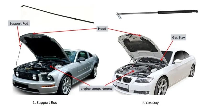
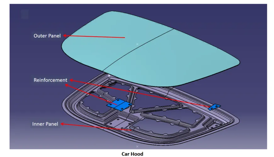
& Reinforcement
Design requirements for Car Hood
1. Hood Head zone for lock striker: In the fig 2.1 shows Hood Head zone for lock striker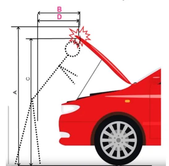
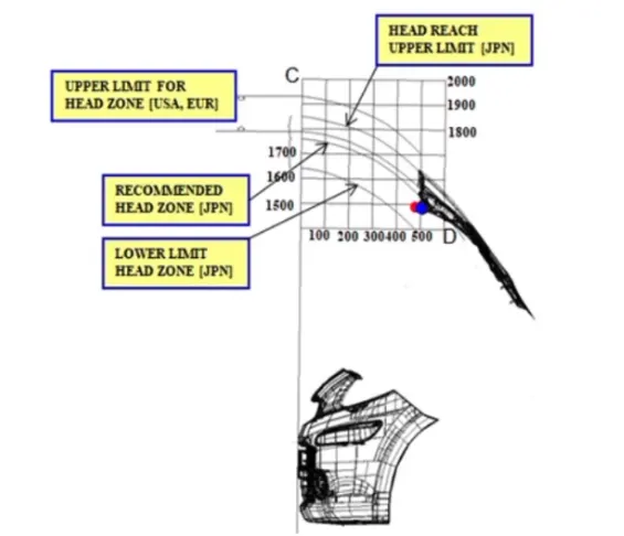 From the Fig. The opening angle of hood will give A, C, B And D with respect to the ground. those A, B, C & D are decided in the head zone. Opening angle varies from region to region depending on average human weight. Depending on the standards we are deciding the angle. So from the angle data, Support rod or Gas stay is designed. The position of Support rod is on the other side of the battery which is shown in the fig. below.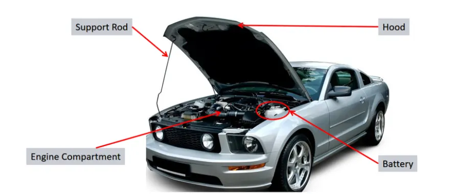
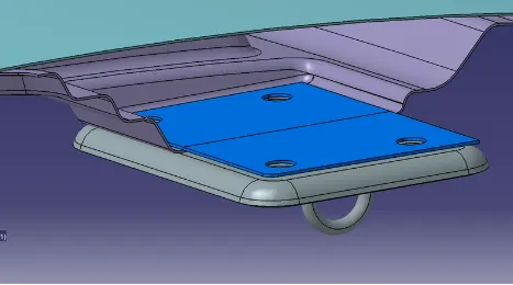
2. Adding latches and stiffener pad: Latches are added where and all the weight is added. On the inner panel we have Hinges and striker, which are attached to the inner panel so due to this attachment the strength of the inner panel is going weak. In order to strengthen the inner panel Latches will play a very important role. Stiffener pad is the sponge-like material place b/w Inner and outer panel to reduce vibrations.
3. Mastic Seals: Mastic Seals place b/w Inner and outer panel to reduce Noise, vibration, and harshness. Every Mastic will have an effect of 80mm Dia locally. shown in the fig 3.1. Inner and outer panel gap is 2 to 5mm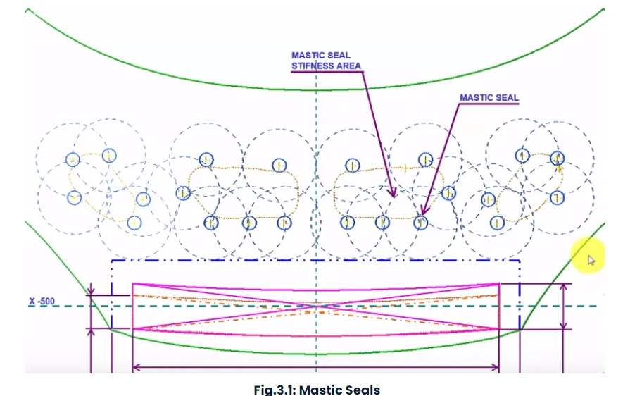
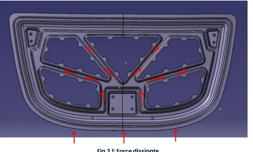
4. Emboss definition: Emboss are provided in the inner panel of the hood assembly. This helps in weight reduction of the hood and also to dissipate the force during collision. Force dissipate is shown in the fig. 4.1 this project design.
a. Deep Drawing: Deep drawing is a sheet metal forming process in which a sheet metal blank is radially drawn into a forming die by the mechanical action of a punch. It is thus a shape transformation process with material retention. The process is considered "deep" drawing when the depth of the drawn part exceeds its diameter.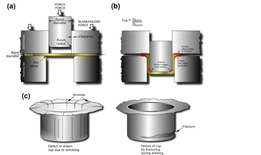
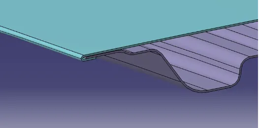
b. Hemming: Hemming is a forming operation in which the edges of the sheet are folded or folded over another part in order to achieve a tight fit. Normally hemming operations are used to connect parts together, to improve the appearance of a part and to reinforce part edges.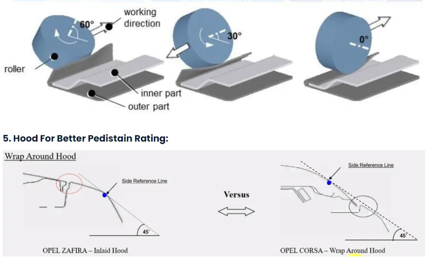
Inlaid Hood:The line which is drawn 45 deg. from ground to Side Reference of carand which is meeting point on fender is called Inlaid Hood.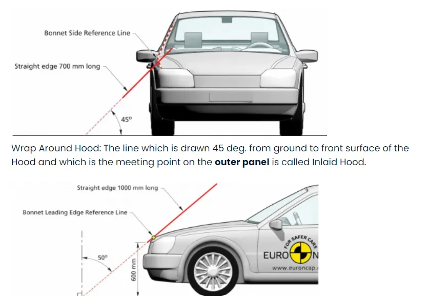
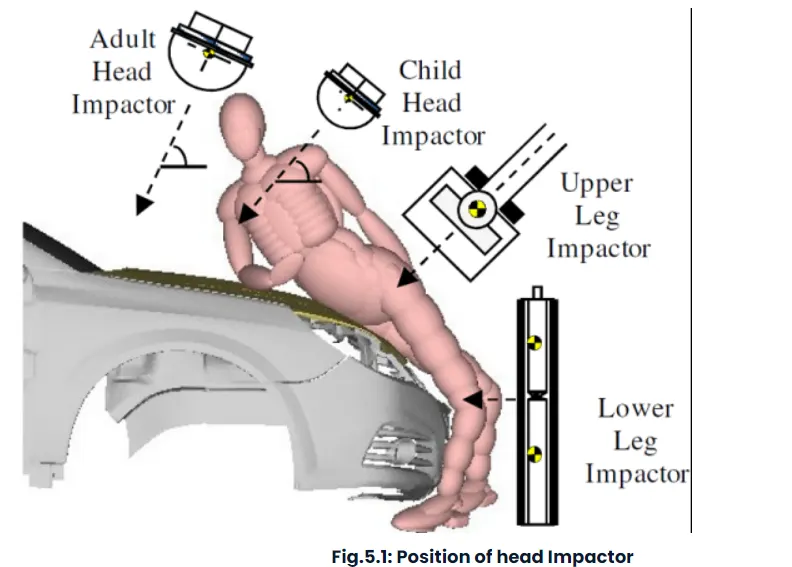
So based on the position of head impactor we are providing emboss and cuts shown in the fig. 5.2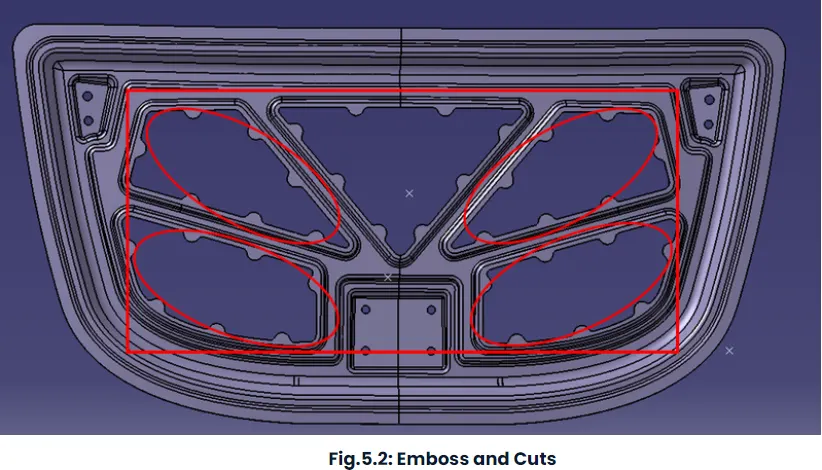
Design Procedure
1. Import the file: File > open > browse file and select the given file (Product name.igs) shown in the fig. 1A.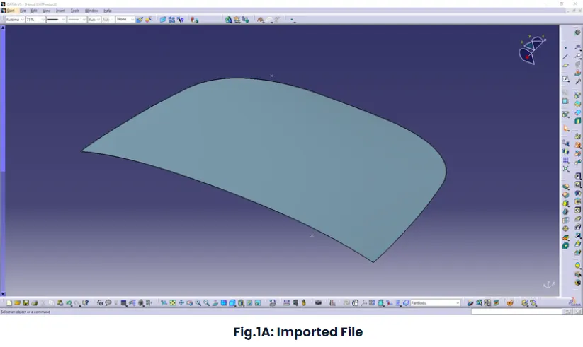
Inner Panel Design:
Given surface is A class and we have Design Inner outer panel using given class A with the help of the Given master section shown in the fig 1B.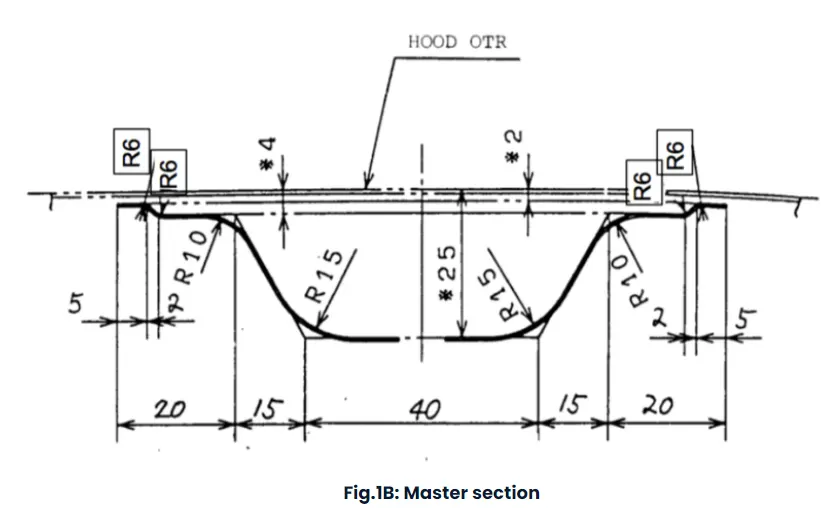
From the master section
1. From the given surface offset to 2mm and split the surface with symmetry axis
2. Create a boundary around the given surface and use parallel curve offset boundary line to 20mm (15+5 from the master section). split the surface using the offset line shown in the fig.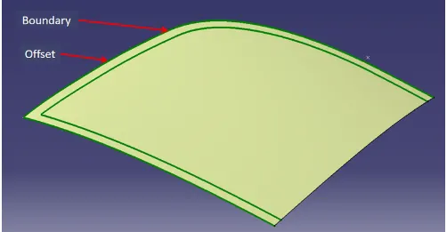
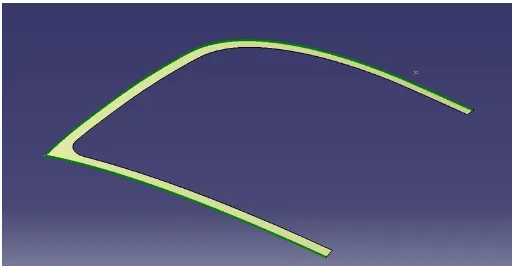
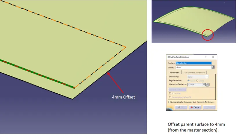
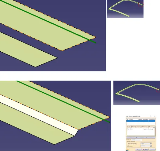
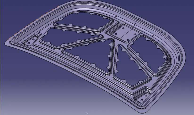
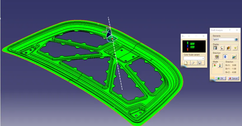
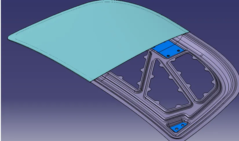
results