Hood design-Week 2
Aim: Designing a Car Hood Inner Panel along with reinforcements using NX CAD.
- Hood –
Car hood/bonnet is a hinged cover that rests over the engine in a front-engine car. A latch is provided under the hood in order to prevent accidental opening during driving. Purpose of hood is to provide access to the engine and battery for repair and maintenance. It also protects these parts from direct sunlight and dust. It also protects the passenger and pedestrian during crash by absorbing and distributing the impact load.
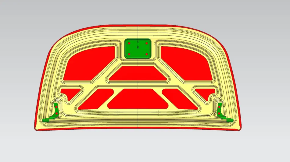
Fig.1 Hood
Part List:
1) Hood Outer Panel
The outer panel works as a metal cover. It is responsible for aesthetics and aerodynamics of the vehicle. Generally the thickness of hood is between 0.65 to 0.85mm.
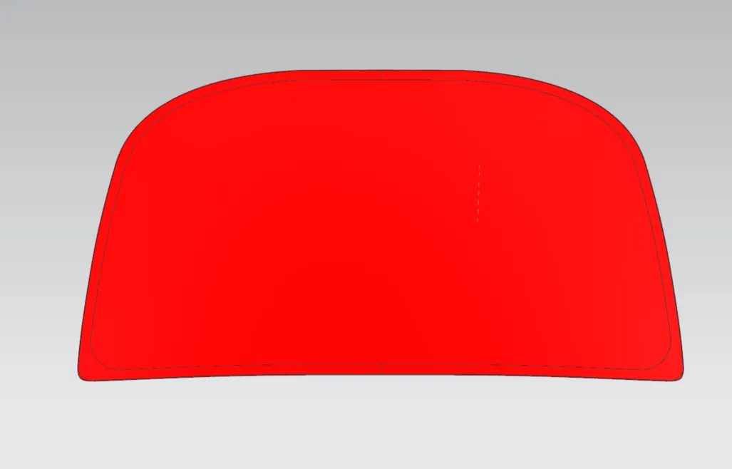
Fig.2 Hood Outer Panel
2) Hood Inner Panel
The inner panel provides strength and supports the outer panel. It is where hood balancer and hinges are attached. Inner Panel is designed in such a way that it distributes the load outward from the Passenger compartment. Cut-outs are created in inner panelto decrease its strength so that the pedestrian does not get any serious enjuiry during frontal crash.
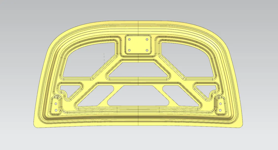
Fig.3 Hood Inner Panel
3) Hinges
Hinges allow the hood to rotate around a fixed axis for opening and closing movement. One part of the hinge is fixed with the engine compartment, while other part is connected to hood.
Fig.4 Right Hinge Assembly
4) Latch and Striker
Latch and striker mechanism is provided to lock the hood, in order to prevent accidental opening of the hood during driving. The latch is present on the engine compartment while the striker is attached to inner part of hood.
Fig.5 Car Hood latch striker
5) Support Rod
It is a device that supports the hood in open position. It is also called as hood balancer rod. Gas stay can also be used depending upon weight of hood.
Fig.6 Support Rod
6) Reinforcements
The reinforcements are provided to add material to the inner panel to provide extra strength to the hood to compensate for loss of strength near component installation regions. Generally the thickness of reinforcements is 1.00mm to 1.50mm.
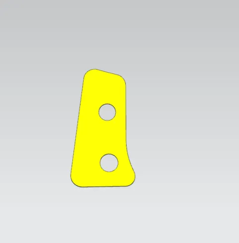
Fig.7 Right Hinge Reinforcement
Latch Trajectory:
It is the path along which the hood rotates during opening and closing movement. The striker on the hood follows a particular path while opening or closing the hood, which is along circumference of a circle with center at the hinge axis. This path is nothing but latch trajectory. It is a very important aspect in hood design, in order to decide hinge, latch and striker installation points.
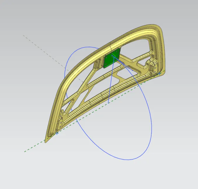
Fig.8 Latch Trajectory
Mastic Sealant:
Mastic sealant helps to locally improve strength of the hood. It is generally a hard rubber part, which is introduced as a paste in between inner and outer panel of the hood, which will get hardened inside the furnace. Every mastic sealant point will have a tendency to improve the local strength in around 80 mm diameter. Considering this, the mastic points are positioned such that most of the hood region is covered. Now-a-days robots are used to place mastics so creating a flange for mastics is not necessary. The blue dots repesents the mastic locations.
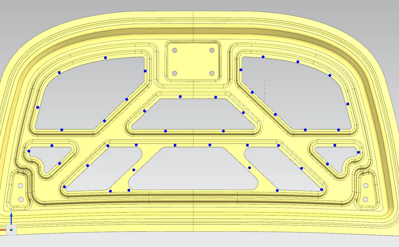
Fig.9 Mastic Sealant Points (highlighted in blue)
Design Methodology:
The procedure followed for designing the hood and its components is as follows,
- First the inner panel is designed from the given master section using the various commands and features. We create the embossing using the offset surface from the original master section. Similarly, we create the cuts on the emboss by sketching and using trim surface option.
- Then the outer panel is designed from the same master section. Here we are supposed to provide the hemming to outer panel. The parameters of hemming are taken as per given values.
Fig.10 Hood Outer Panel with hemming
- Now, on the inner panel, the embossing for hinge and striker are produced by considering their respective dimensions and assembly positions. First the emboss for hinge is created and then by fixing the hinge into its position, we draw an axis passing through both side hinge axes to form a common axis. And then we position the striker such that it will move along circumference of a circle whose center is at midpoint of the common axis. Thus, position of striker is decided and we can create emboss for the same.
- Using the hinge emboss we created, we can create our hinge reinforcements by creating new parts in the assembly itself.
- Data Povided –
Outer Panel Thickness – 0.75mm
Inner Panel Thickness – 0.75mm
Reinforcement Thickness – 1.5mm
Important Features used in designing:
- Trim Body – It is used to trim one or more bodies using a face or plane. You can also specify the bodies to retain and the bodies to discard.
- Offset Surface – It allows you to offset one or more existing surfaces.
- Offset in Face – This command will allow you to offset particular edges or curves on selected faces.
- Trim Sheet – It is used to trim off a portion of a sheet body using curves, faces, edges or planes.
- Through Curves – It will allow you to create a body Through multiple sections, where it’s shape changes to pass through each section.
- Law Extension – This command extends a curve or edge to create a sheet body at desired angle length by changing the rules under angle law and length law.
- Trim and Extend – It helps you to trim and extend intersecting surfaces and make corner at their intersection.
- Face Blend – It creates fillets between faces.
- Edge Blend – It creates fillets on edges.
- Extend Sheet – It will allow you to extend an existing surface to required distance.
- Emboss – Emboss command creates an embossing by modifying a body with faces created by projecting a curve/section along a direction. You can modify the emboss using options like endcap location and draft angle.
- Projected Curve – It is used to project an existing curve/curves on a selected plane or surface by selecting a direction for projection.
- Mirror Geometry – As name suggests, it allows you to mirror geometries about selected plane or surface.
- Sew – It combines sheet bodies together by sewing their common edges. There shouldn’t be any gaps larger than specified tolerance.
- Thicken – It is used to convert a surface to solid body by providing thickness.
- Extrude – It helps you to create a feature from a sketch. You are also able to create thin feature using a sketch or curve under this command.
- Wave Geometry Linker – With this you can create, associative or linked copies of any entity of a part into other parts. It may be a surface, edge, curve, body, sketch etc. The changes made to the original entity will be reflected in the copy of that entity.
Sheetmetal Operations in Car Hood Manufacturing Process:
- Deep Drawing –
It is a sheet metal forming process in which a sheet metal blank is radially drawn into a forming die by the mechanical action of a punch. The process is considered deep drawing when the depth of the drawn part exceeds its diameter.
Fig.11 Deep Drawing
- Hemming –
Hemming is a forming operation in which the edges of the sheet are folded over other part or simply folded in order to achieve a tight fit. In car part production, hemming is used in assembly as a secondary operation after deep drawing, trimming and flanging operations to join two sheet metal parts (outer and inner) together.
Relief - We have to provide hemming relief at corners to avoid forming defects. A minimum of 3mm flange length is required at corner radius.
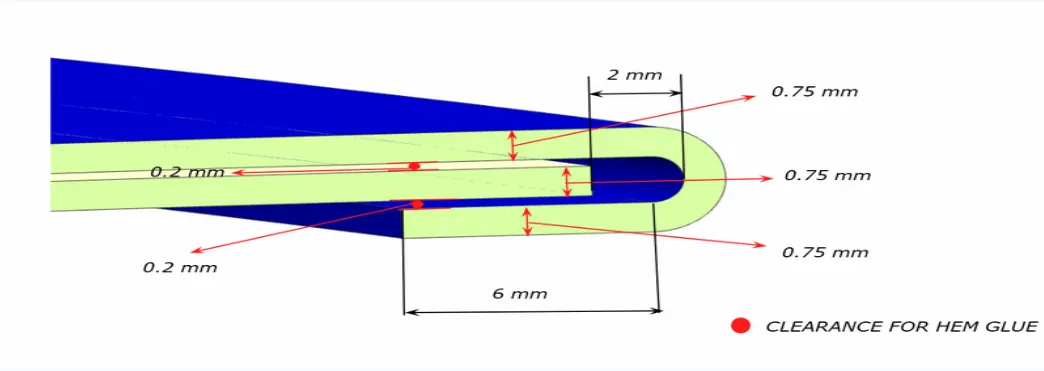
Fig.12 Hemming process
Fig.13 Roller Hemming process in 3 Stages
- Embossing –
Sheet metal embossing is a stamping process for producing raised or sunken designs or relief in sheet metal. This process is carried out by means of matched male and female roller dies, or by passing the sheet or rolls of metal between rolls of desired pattern.
Fig.14 Simple Embossing with its Section view
- Piercing –
It is a shearing process in which raw sheet metal is pierced with a machining tool, resulting in the creation in a particular shape hole in the sheet. The major difference between blanking and piercing is that in blanking the cut out is the workpiece and outer part is scrap, while in piercing, the cut out is scrap and the outer sheet is the workpiece.
Fig.15 Piercing and Blanking
Conclusion: I designed the car hood along with its components and assembled the same, using NX CAD, under given parameters.