Hood Design
OBJECTIVE
To design a Hood or Bonnet BIW that satisfies the manufacturing requirements and functional equipment of Hood or Bonnet
INTRODUCTION
Hood may be Hinged at either front or rear edges in earlier models. it maybe split into two sections one each side, each Hinged along the centreline. A further variant combines the bonnet and wheel arches into one section and allows the entire front body and wheel arches into one section and allows the entire front body work to tilt forward around a pivot near the front of the vehicle.
Hood is made aerodynamic in shape to reduce air effect and used to decorate the front portion of the car and to add a luxurious look of cars. Hood generally used to cover car engines, radiators and any other components, therefore the hood must be designed in such a way that all the maintenance on the engine. In addition to that f it come across any accidents from the front portion most of the time the hood system gets damaged first and absorbs most of the impact energy resulting from the crash.
MATERIAL FOR HOOD
To simulate head impact phenomenon between head form impactors and composite bonnet. Then the behaviour of three identical bonnets made of steel, aluminium and composite have been investigated by the developed model. Aluminium is used most of the times, due to its lower weight the aluminium hood exhibits lower emissions during its use phase. Consequently, for indicators where the vehicle use phase is an important contributor to the environmental performance, the overall result of Aluminium hood exhibits a significantly lower impact than the steel one.
HOOD DESIGN DATA
WAY OF APPROACH
SHEETMETAL OPERATIONS
1.BLANKING AND PIERCING
In Blanking, Piercing and sharing processes a punch and die are used to modify webs. The tooling and process are between the two are same, only the terminology is different. In blanking the punched-out piece is used and called blank where as in piercing the punched-out piece is scrap. The process for parts manufactured simultaneously with both techniques is often termed pierce and blank, an alternative of piercing is punching
Purpose:
- Reduce the body of weight
- Improve the strength of the body
- Improve Mileage of car
- Distribute impact force
2.DEEP DRAWING
Deep drawing sheet metal is used to form object with dept. It is plastic deformation in which a flat sheet metal or plate is formed into a recessed three-dimension part with a depth several times the thickness of the metal. The process of deep drain begins with a flat sheet metal held on the upper surface of the die. It is used in manufacturing inner panel. Material used is aluminium as it can absorb twice the crash energy of mild steel. Lighter dent free and make body panels thicker while still lowering weight.
Purpose:
Operation in which thickness of the shell wall is reduced and its surface smooth. When material gets compress between punch and die, which reduce the thickness and increase the height of the cup.
3.EMBOSSING
Embossing is a metal forming process for producing raised or sunken designs or relief in sheet material by means of matched male and female roller dies, theoretically with no change in metal thickness, or by-passing sheet or a strip of metal between rolls of the desired pattern. Emboss should be in 7 degree to 11-degree incline in angle and it should not be in 90-degree angle, why because when we do stamping in manufacturing the stamping tool fits the sheet metal hence it will not come out of that sheet metal, So this is the main reason why the emboss face is in angle.
4. HEMMING PROCESS
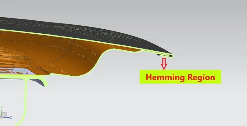
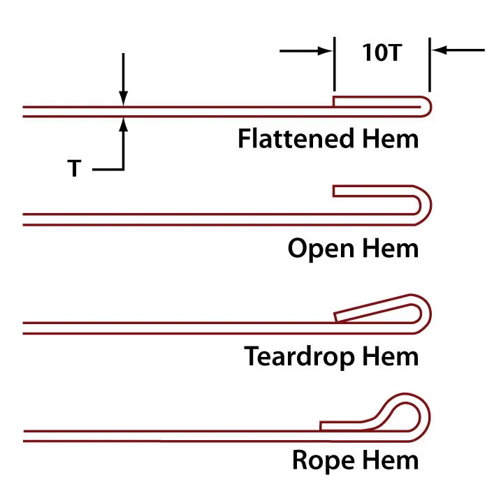
Hemming is a forming operation in which the edges of the sheet are folded or folded over another part in order to achieve a tight fit. Normally hemming operations are used to connect parts together, to improve the appearance of a part and to reinforce part edges. Conventional die hemming.
Types of Hemmings:
STEPS IN DESIGNING THE HOOD
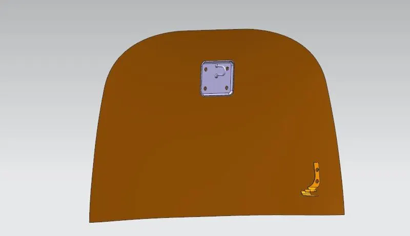
1. In this challenge only the outer panel sheet, Hinge assembly and Latch (Striker) is provided
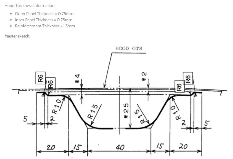
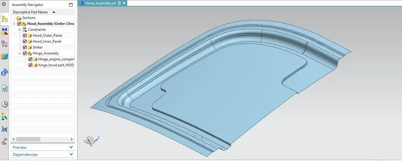
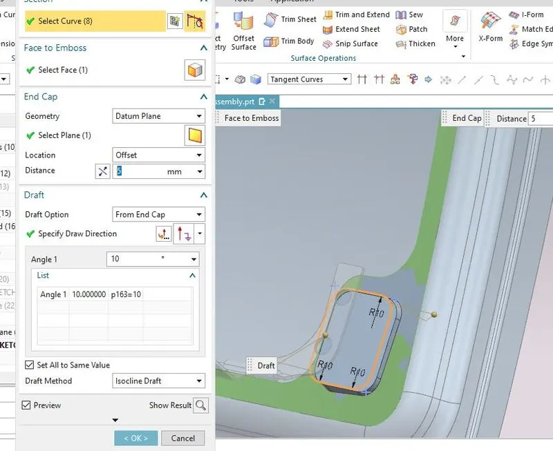
2. From the outer panel Inner panel need to be created. This can be achieved by offsetting the surface into distance which is refered in the master section above. Before offsetting the surface , surface need to be cut into half because the surface is symmetrical. So after setting up the offseeting the surface the sharp edges should Edge blend or Face blend with a radius. After this a Emboss need to be created to the outer panel side with a distance of 5mm and draft with angle of 10
3. After this Hinge need to be fixed, for this Hinge surface need to be placed on the location. After that with parallel to the the Hinge face a datum plane need to created and with respect to that Hinge reinforcement need to be created. A sketch need to be created with repect to the datum plane which is created. After setting up the sketch Emboss the surface outwards that is away from the outer panel. So in that reinforcement Hinge hole can be mounted and engine component will be mounted on the engine side. The edge should be blended with edge blend command
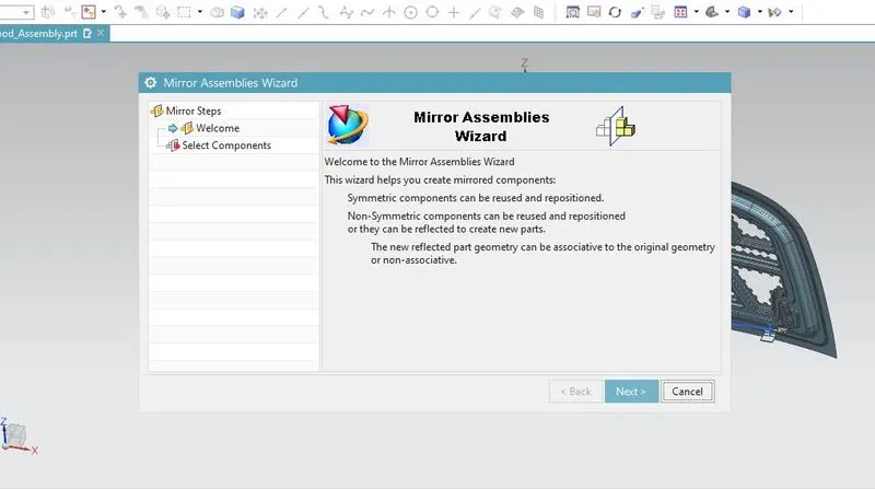
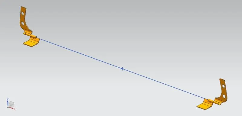
4. After placing the Hinge, Latch should be placed at the correct location. Inorder for that the hinge should be parallel to Hinge reinforcement face and should be parallel to X axis which is current axis in this model. So with respect to that hinge need to be mirrored on the other side using option Mirror assembly.
5.After mirroring the Hinge a axis need to be crated from the 2 hinge side and create a mid point for the axis.
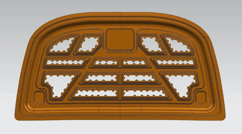
6. After setting up the line sketch the drawing in the inner panel inorder to setup the Emboss for the structural rigidity and for the force descipation when the hood hit with a pedesterian. And make a cutout above the emboss for the Mastic seal to be setupped.
Mastic sealants are elastic compounds that behaves like the rubber. It is placed between the outer and inner panels. Initially it is in paste form but after the hot furnace bath, it will get hardened thus joining the outer panel and inner panel, Mastic sealants has the tendency to increase the strength of the panel and has the tendency to increase the strength of the panel and has the influence of 80mm diameter.
After all this mirror the geometry to the other side.
7. With repect to the above middle point a circle need to be drawn where the circle need to passes through the middle of the lock in the stiker. From the middle point draw a line which toucjes the circle and from the end point draw a line which is tangent to circle. And after exiting from the sketch draw a line which is perpendicular to the lock. Then using this 2 lines by constraints the latch position can be placed, that is the first align the end point of the line which is drawn at first with the line drawn at second. This results in second will be in the place of tangent line lwhich is drawn at first. Then again align with second line end point with the tangent line , so that the hinge will come close to the inner panel, if the distance from the latch to inner panel is less try to change the the vertical line end point and go on with the above method.
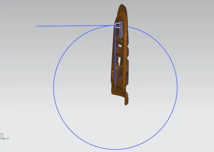
[Note: in the above after placing the Latch the reinforcement need to created with respct to the Latch current position. In this face below the latch is extracted and with respect to the Latch reinforcement is created]
8. After completing the inner panel, it should be thicken to 0.75mm
9. Then the Hemming portion for Outer panel need to setupped. From the outerpanel surface need to offset for the hemming surface which is below the inner panel, where a 6mm a strip need to created. And for that from the face side the cuve need to be offseted to about a distance and from the outer edge of the outer panel and newly offseted curve should be law extended. So after this by trimming the below hemming portion can be setuped. And after this for the curve portion using face blend in that change option to 3 faces and select the approporiate surface and blend into curve where joining the both surfaces.
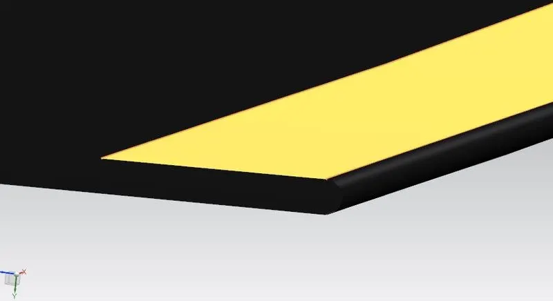
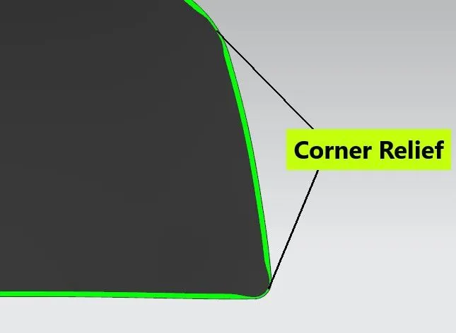
10. Then setup a corner relief for the rollers to hemm the surface properly. So draw a sketch for the corner relief and and trim the sketch to form the corner relief. After that mirror the geometry and sew the surfaces and thicken to 0.75mm.
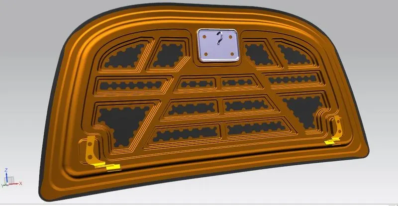
FINAL BODY
CONCLUSION
THUS THE OUTER PANEL, INNER PANEL, HINGE ASSEMBLY AND LATCH WITH THE NECESSARY REINFORCEMENTS ARE CREATED WITH RESPECT TO THE MASTER SECTION MENTIONED WITH THE NECESSARY PARAMETERS