Hood design-Week 2
AIM:
- To design Hood outer Panel and Hood Inner panel and provide necessary reinforcements as per the given master sections.
- To assemble the hinge assembly in the Hood Inner panel.
- To provide mastic data points as per following the design rules.
- To provide the trajectory path of the latchet and fix the striker in the Hood Inner panel.
- To design the Hood outer panel for the hemming process and provide hemming relief as per the master section and thicken the surface.
HOOD DESIGN:
The hood or bonnet is the hinged cover over the engine of motor vehicles. Hoods can open to allow access to the engine compartment, or trunk on rear-engine and some mid-engine vehicles for maintenance and repair.The hood release system is common on most vehicles and usually consists of an interior hood latch handle, hood release cable and hood latch assembly. The hood latch handle is usually located below the steering wheel, beside the driver's seat or set into the door frame.
Hood contains
- Hood Outer Panel
- Hood Inner Panel
- Striker
- Hinge assembly Mechanism
Hood Outer Panel:Hood Outer Panel is Outer surface of the hood.It is normally made up of steel or aluminum,Carbon Fibre.In Outer panel,hood inner panel is attached with Hood inner panel through hemming process.Mastic sealants are applied in between Hood inner and Hood outer panel to avoid wear and tear and vibrations.
Hood Inner Panel:Hood Inner panel has mastic locators where mastic sealants are placed.Hood Inner panel must be designed in such way that whenever car hits a pedestrian, It should crash in such way that injury for the passenger and pedestrian must be minimal.
Mastic Sealants: Mastic Sealants are sealants applied between Hood inner panel and Hood outer panel.When heat is applied, it expands and attaches the inner panel with outer panel.
Hood Struts: When you check underneath the hood, your hood struts, or hood shocks, are the part that helps support the weight of the heavy hood as you lift it up to check the engine. They help you to lift and hold up the hood of your car, even before you prop it up.
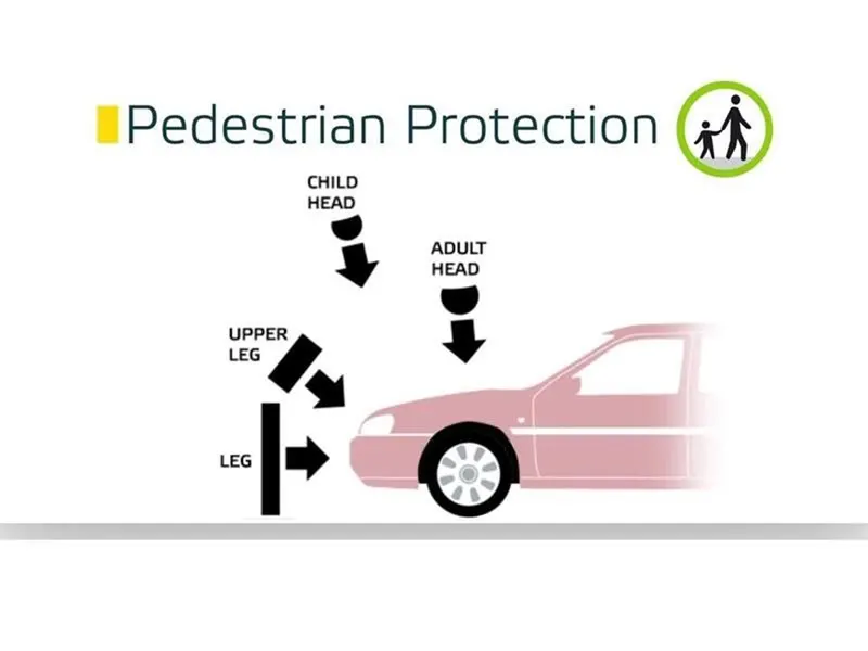
Many pedestrian crashes involve a forward moving car (as opposed to buses and other vehicles with a vertical hood/bonnet). In such a crash, a standing or walking pedestrian is struck and accelerated to the speed of the car and then continues forward as the car brakes to a halt. The pedestrian is impacted twice, first by the car and then by the ground, but most of the fatal injuries occur due to interaction with the car. Vehicle designers usually focus on understanding the car-pedestrian interaction, which is characterized by the following sequence of events: the vehicle bumper first contacts the lower limbs of the pedestrian, the leading edge of the hood hits the upper thigh or pelvis, and the head and upper torso are struck by the top surface of the hood and/or windshield
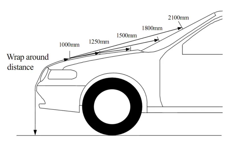
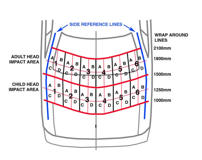
Wraparound Distance (WAD): The shortest line of the lines that connects the reference plane with any point on the vehicle, which passes through the vehicle's front and front's upper-surface within the vertical plane that includes the vehicle's fore-aft axis.For Child wrap around distance WAD is 1000mm with impact angle approximately 40-50degree at speed of 40km/h.For an adult WAD is 1700mm
A New Car Assessment Program is a government car safety program tasked with evaluating new automobile designs for performance against various safety threats. The National Highway Traffic Safety Administration's New Car Assessment Program (NCAP) created the 5-Star Safety Ratings Program to provide consumers with information about the crash protection and rollover safety of new vehicles beyond what is required by Federal law.
The European New Car Assessment Programme (Euro NCAP) is a european voluntary car safety performance assessment programme.
The Bharat New Vehicle Safety Assessment Program, usually known as the Bharat NCAP, is a proposed NCAP for India. Cars sold in the country will be assigned by star ratings based on their safety performance. It will be implemented in phases, according to the plans being drawn up by the National Automotive Testing and R&D Infrastructure Project. It is the 10th NCAP in the world and is being set up by the government of India.
It is proposed that this BNVSAP would start the official testing from October 2017 onwards. The car testing protocols is defined by ARAI as follows:
- Frontal offset testing (64 km/h proposed)
- Side impact testing
- Pedestrian protection testing
- Rear impact testing
- Child dummy dynamic crash testing
Japan New Car Assessment: JNCAP aims for
- informing shopper of the safer cars and the safer child restraint system. CRS.
- promoting manufacturers to develope the safer cars and the safer CRS.
- popularizing the safer cars and the safer CRS.
JNCAP tests ,evaluates and publishes about
- car active safty performance
- car passive safety performance
- car automatic emergency call systems equipment
- child restraint system performance and usability
Mobile progressive deformable barrier:
The test car is propelled at 50 km/h (31 mph) into a moving deformable barrier mounted on an oncoming 1400 kg trolley, also travelling at 50 km/h at a 50% overlap. This represents hitting a mid size family car. Two adult male dummies are seated in the front and two child dummies (a 6 year old and a 10 year old) are placed in the back. The aim is to assess the crumple zones and the compatibility of the test car.
Full width rigid barrier:
The test car is driven into a rigid barrier with full overlap at a speed of 50 km/h (31 mph). A small 5th Percentile dummy is seated in the driving position and in the rear seat. The aim is to test the car's restraint system, such as air bags and seat belts
Mobile side impact barrier:
A deformable barrier is mounted on a trolley and is driven at 60 km/h (37 mph) into the side of the stationary test vehicle at a right angle. This is meant to represent another vehicle colliding with the side of a car.
Side pole:
The car is propelled sideways at 32 km/h (20 mph) against a rigid, narrow pole at a small angle away from perpendicular to simulate a vehicle travelling sideways into roadside objects such as a tree or pole.[22]
Far side impact:
The BIW(frame) of the vehicle is attached to a sled is propelled sideways to provide accelerations experienced by the vehicle in the side and pole tests, but on the far side of the vehicle. The far side testing was implemented in 2020 to help combat far side injuries (where the driver is struck from the opposite side). The ‘excursion’ of the dummy - the extent to which the dummy moves towards the impacted side of the vehicle - is measured.
If the vehicle is equipped with centre airbags then a co-driver (front passenger) is added in either the mobile side impact or the pole test to evaluate its effectiveness.
Whiplash
The vehicle seat is propelled forwards rapidly at both 16 and 24 km/h (9.9 and 14.9 mph) to test the seat and head restraints capabilities to protect the head and neck against whiplash during a rear impact.
Vulnerable road users (pedestrians & cyclists)
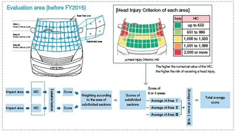
Head Impact
Upper Leg Impact
Lower Leg Impact
AEB Pedestrian
AEB Cyclist
Operations:
Hemming:
Hemming is a forming operation in which the edges of the sheet are folded or folded over another part in order to achieve a tight fit. Normally hemming operations are used to connect parts together, to improve the appearance of a part and to reinforce part edges.
In car part production, hemming is used in assembly as a secondary operation after deep drawing, trimming and flanging operations to join two sheet metal parts (outer and inner) together. Typical parts for this type of assembly are hoods, doors, trunk lids and fenders.
The accuracy of the hemming operation is very important since it affects the appearance of the surface and surface quality. Material deformations, which occur during the hemming process, can lead to dimensional variations and other defects in parts. Typical hemming defects are splits or wrinkles in the flange, material overlaps in the corner areas or material roll-in.
Conventional die hemming
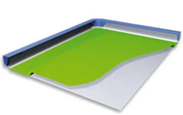
Conventional die hemming is suitable for mass production. In die hemming, the flange is folded over the entire length with a hemming tool. Normally the actual hemming is a result of a forming operation in which the flange is formed with a hemming tool after the drawing and trimming operations have been completed. The formed flange is then hemmed in several process steps. These steps include, for example, the pre-hemming and final hemming depending on the respective opening angle of the flange. Production plants for conventional die hemming are very expensive, but the cycle times are very low.
Roll hemming
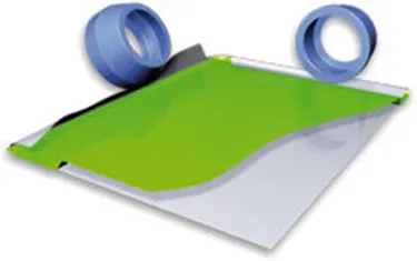
Roll hemming is carried out incrementally with a hemming roller. An industrial robot guides the hemming roller and forms the flange. Roll hemming operation can also be divided into several pre-hemming and final hemming process steps. Roll hemming is very flexible to use and tool costs are significantly lower as compared to those of conventional die hemming. However, the cycle times are much higher since the hemming is realized using a hemming roller which follows a defined path.
Hood Design Procedures:
Hood Inner Panel:
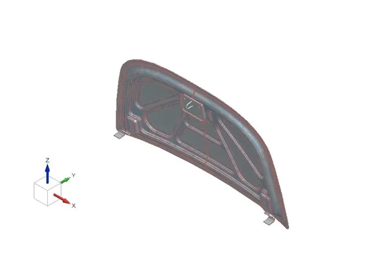
- Hood Inner panel surface is extracted from Hood Outer panel using copy or wave geometry linker commands.
- Hood inner panel is offsetted at distance as per master section and trimmed using offset in face command.
- Face blend or edge blend is applied on the surface.
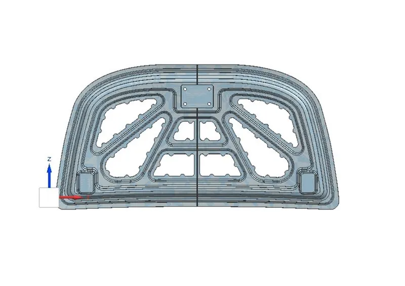
- Emboss is applied on the surface with gap for striker and hinge assembly emboss.
- Another emboss is applied with mastic points cut outs.
- Sheet is trimmed for mastic points.Trims of the inner panel should be designed in such way that force applied during acciendatal impact,Hood crashes and disspiates force outwards so that passenger safety is ensured.
- Hinge assembly emboss should be flat surface.It can be analysed by local radius analysis.
- Inner panel is mirrored and hinge is assembled using assembly constraints.
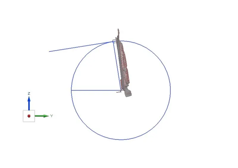
- From the hinge assembly axis,striker trajectory is formed and striker is aligned.
- Emboss for Striker is formed and striker is assembled.
Striker Trajectory path:
Hood Outer Panel:
- Hood outer panel is offsetted at a distance as per the master section for applying hemming.
- Using law extension7 tritangent fillet,Hood outer panel is hemmed.
- Hemming relief angle is applied on edges.
Conclusion:
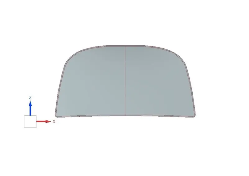
Hood of the Car is designed as per the master section.Hood Outer panel is hemmed and Hood inner panel is designed with mastic points and emboss draft angle and fillet radius.Striker and Hinge Assembly is assembled with hood inner panel.