Hood design-Week 2
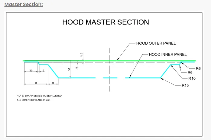
Design Hood Outer Panel, Inner Panel and the necessary reinforcements by following the Master Section mentioned with the Design parameters explained in the videos.
Submit an ASSEMBLY of Hood Inner Panel, Outer Panel, Latch, Hinge and the Reinforcements.
A detailed report about the Hood Design which includes a detailed explanation about hood and its components, Latch Trajectory, Mastic Data, Emboss Definitions, Manufacturing process like Deep-Drawing and Hemming, and all the parameters followed in the design.
The report should be well-formatted and should have a good flow of content. Add all the relevant images
Data to be used:
Hood Thickness Information
- Outer Panel Thickness = 0.75mm
- Inner Panel Thickness = 0.75mm
- Reinforcement Thickness = 1.5mm
Solution:
Introduction:
Hood is main component of a car at the front portion. It is used to decorate the car & add luxurious look. The shape of the bonnet is made aerodynamic in order to minimize the air effect
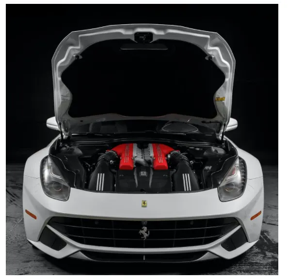
The hood (North American English) or bonnet (Commonwealth English) is the hinged cover over the engine of motor vehicles. Hoods can open to allow access to the engine compartment or trunk (boot in Commonwealth English) on rear-engine and some mid-engine vehicles) for maintenance and repair.
A car hood also referred to as a bonnet in some other countries is the hinged cover that rests over the engine of a front-engine vehicle. Its purpose is to provide access to the engine for repair and maintenance. Car hoods are typically constructed from steel and sometimes from aluminum.
Hood design consideration:
The hood of a car is considered as the frontal BIW enclosure component. Bonnets are designed to reduce air resistance as the air flows around the car. Apart from this, bonnets are also designed to meet several other requirements. They serve a great deal of purpose in protecting the passengers inside the car & the pedestrians in the event of an accident. It also acts as the cover for the engine.
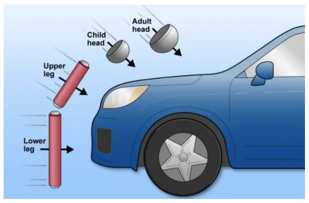
- The European New Car Assessment Programme (Euro NCAP) is a European car safety performance assessment program which has developed test specifications & rating systems for assessing pedestrian injuries during impacts with the front of vehicles such test include a series of tests using impacts designed to bio-mimic a collision at speed of 40 km/h.
- They describe a situation in which a pedestrian is situated laterally & a car first hits one of his legs. Test are conducted on the leg, upper leg & most importantly the head, as head trauma is most commonly responsible for casualties.
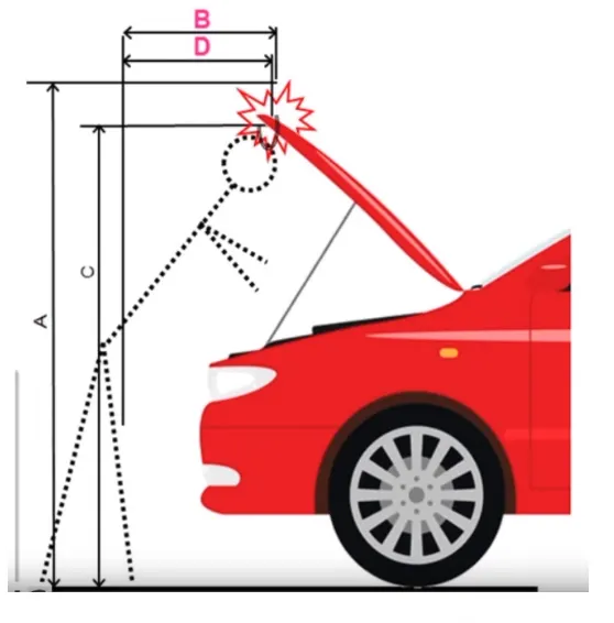
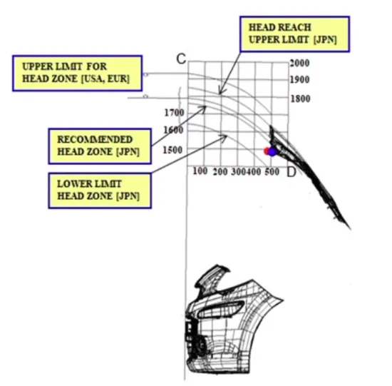
- So to avoid severe injuries to the head, the high impact area for adults & children are subjected to less thickness. Also no reinforcement should be provided in that area as during head collision, the hood will absrob the head impact energy leading to collapse of the hood & thus protecting severe head injury.
- Another important criteria for the hood design is the protection of the occupants inside the car during front collision. The design of the hood should be in a such a way that the during the collision, the force should travel in the upward direction through the embosses & directed towards the body of car. Thus protecting the occupants inside.
Following parts are using in hood assembly for this report,
- Hood outer panel
- Hood inner panel
- Hinge assembly
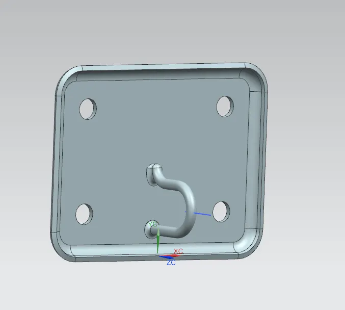
- Striker assembly
Hood thickness-
Outer panel thickness= 0.75 mm
Inner panel thickness= 0.75 mm
Reinforcement thickness= 1.5 mm
Inner Panel:
- In the inner panel only we can research & implement the safety of pedestrians & as well as the driver. In this panel only we can attach the reinforcement, embossed, mastic points etc.
- It is an object of the present invention to provide a hood inner panel capable of reduction of a reaction force of the hood inner panel even if a level of deformation of a hood of a vehicle increases, & ensuring a sufficient energy absorption capacity.
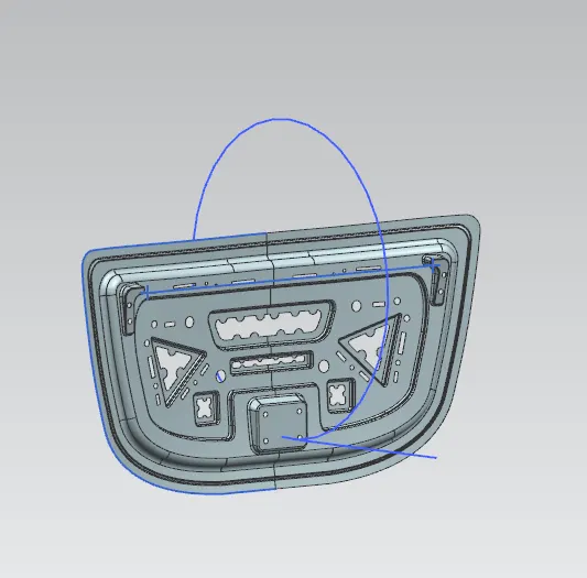
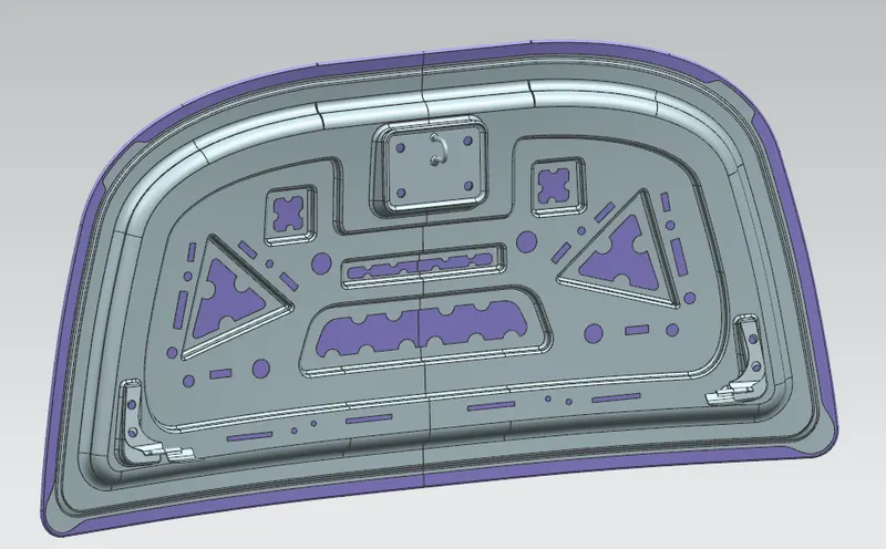
1. The Inner panel is given as
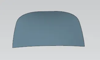
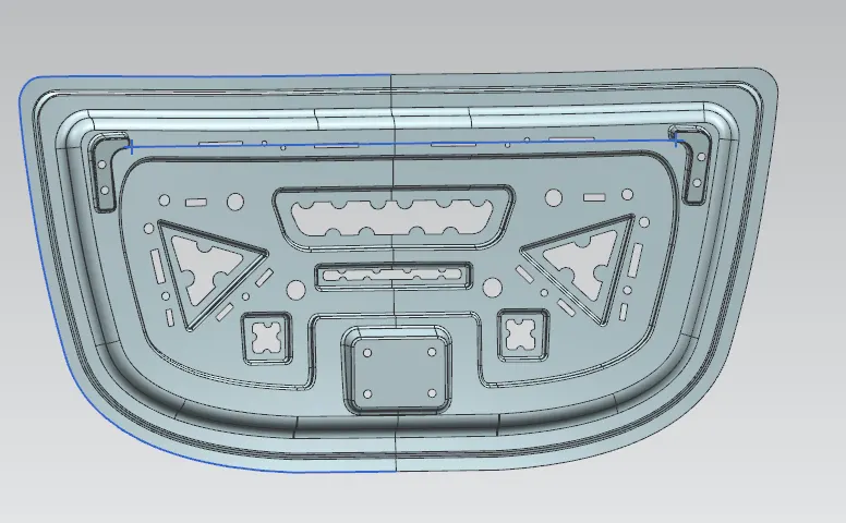
So according to the input design given the outer model should be modified to get the final input panel model.
First the outer panel should be exactley halfed into middle using mid plane and should work on the half anel.
Then all the features should be mirrored and and sewed together.
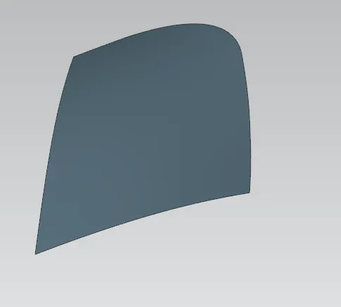
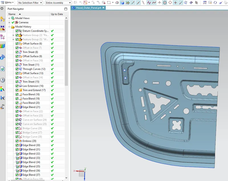
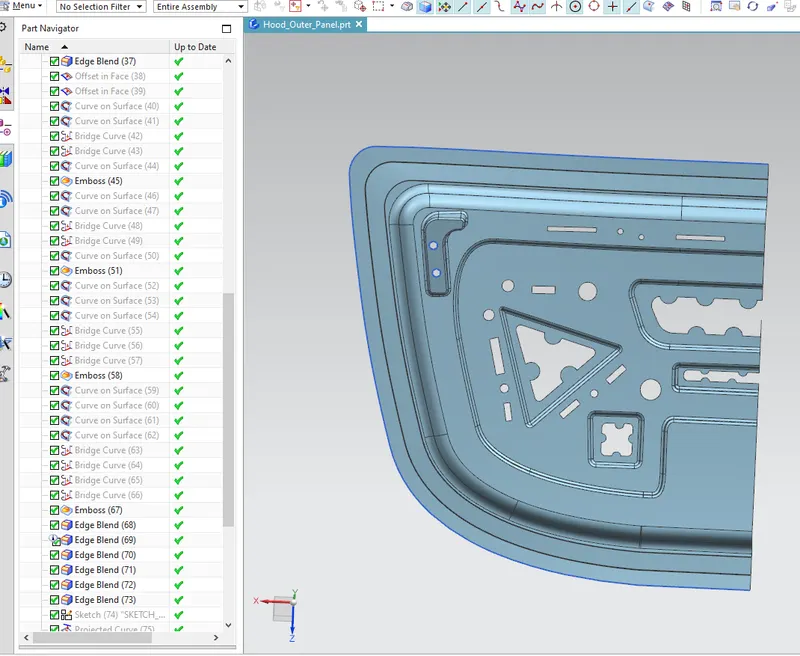
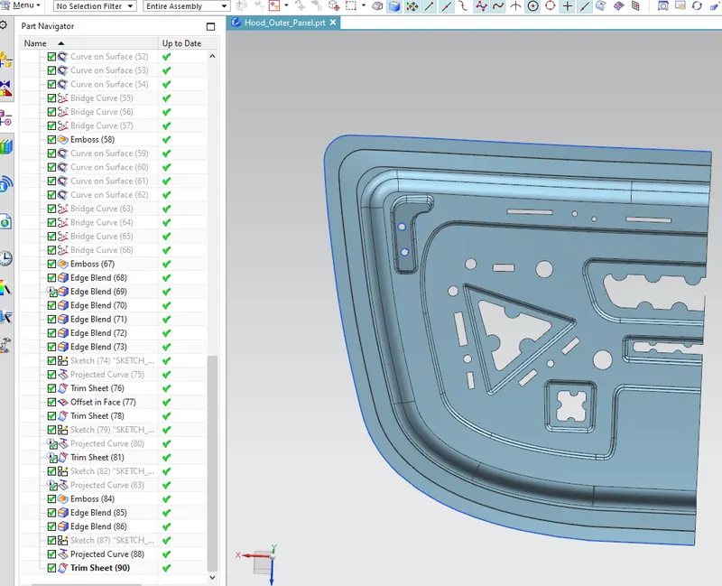
The below operations are done to get the output
1. Wave Geometry Linker
2. Trim Sheet
3. Offset Surface
4. Offset curve in face
5. Law Extension
6. Trim and Extend
7. Face Blend
8. Emboss
9. Bridge Curve
10. Edge Blend
11. Projected Curve
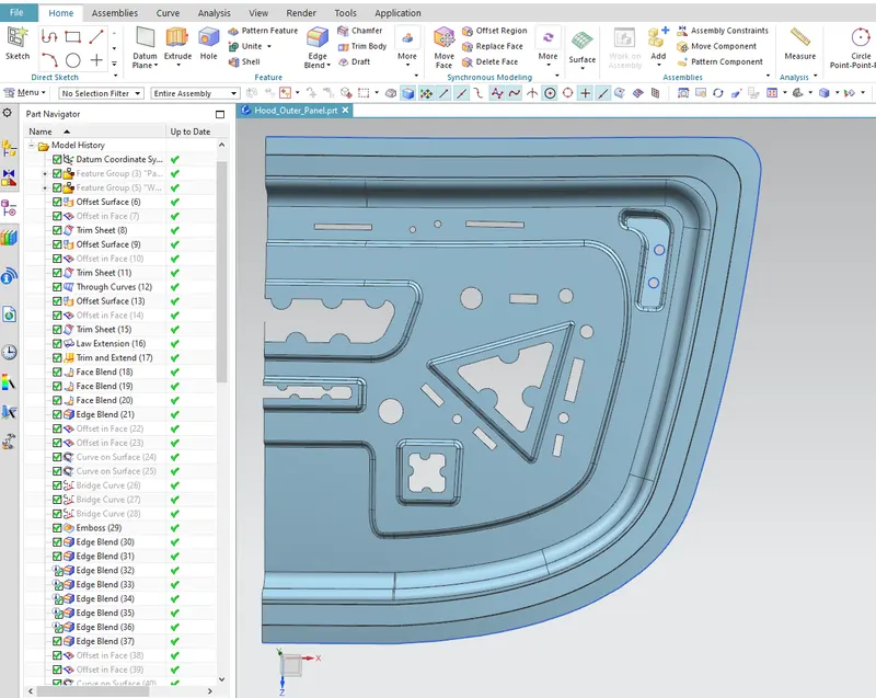
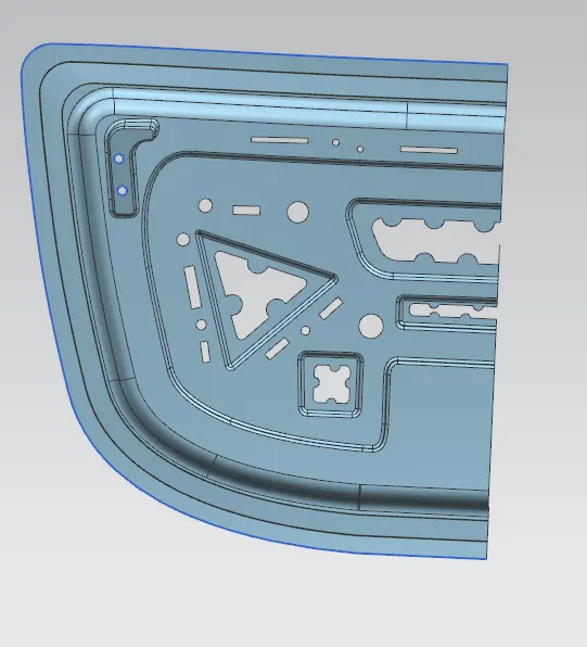
Tree
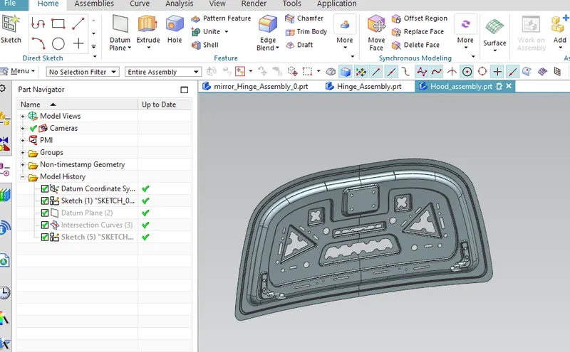
Hinge Assembly:
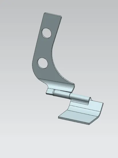
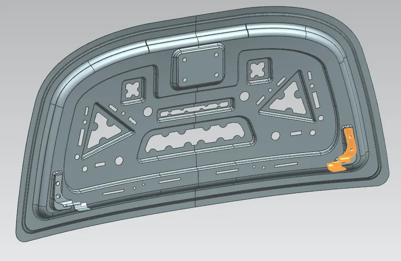
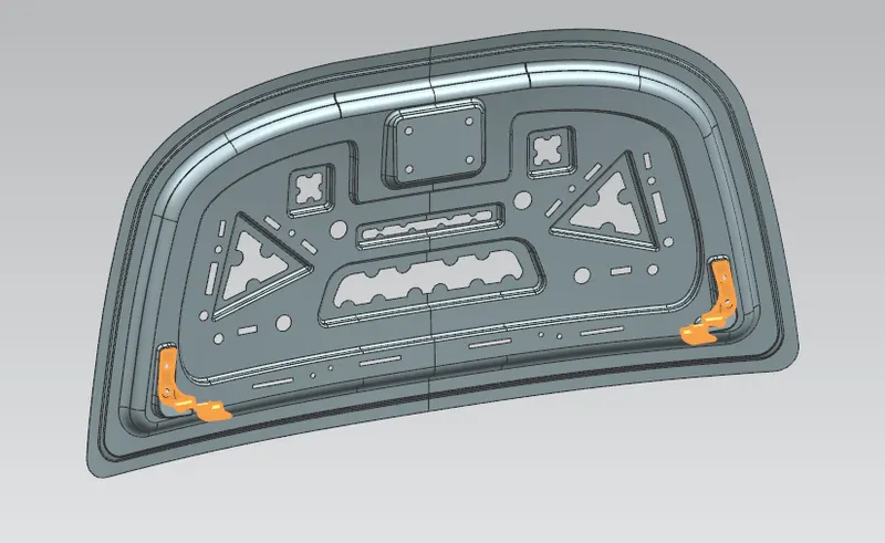
First hinges are placed on to the embosses and as inner panel is applied with fixed constraint hinge is placed parallel and touch constaint.
Then the hinge is mirrored with assocative connection to other side to get the same hinge position on other side of the inner panel.
Striker Assembly:
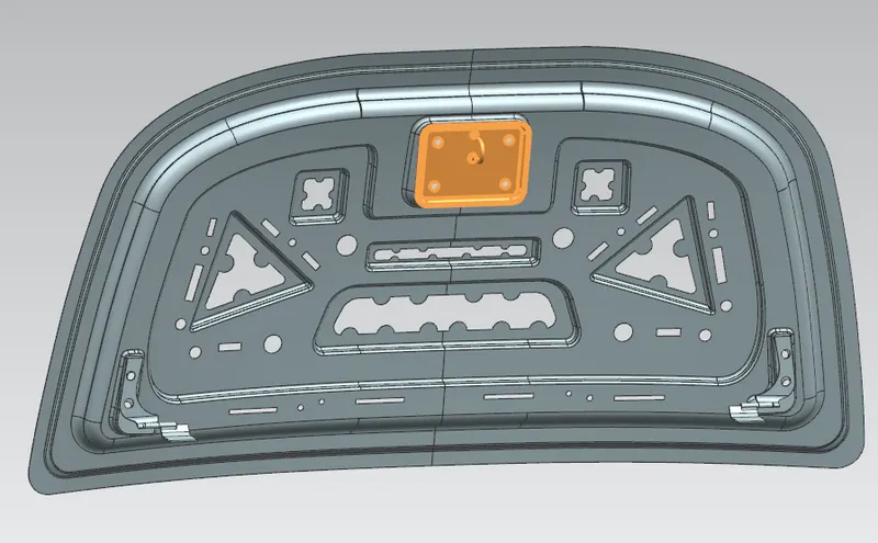
Latch & striker is used for locking the hood with the car. It is usually placed on the space provided on the inner panel.
Hemming:
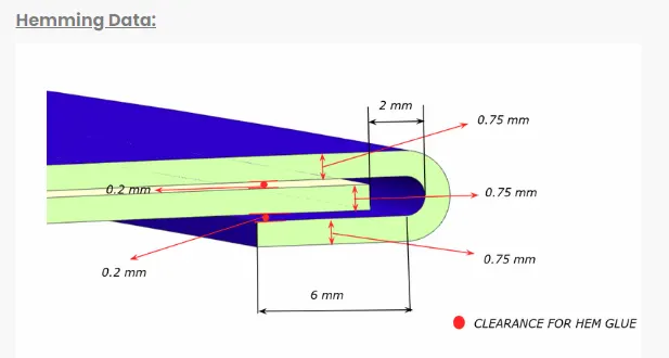
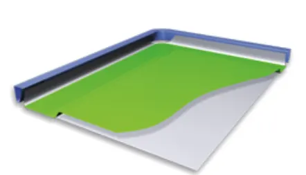
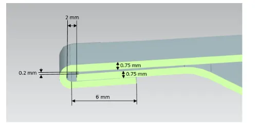
Hemming is a forming operation in which the edges of the sheet are folded or folded over another part in order to achieve a tight fit. Normally hemming operations are used to connect parts together, to improve the appearance of a part and to reinforce part edges.
In car part production, hemming is used in assembly as a secondary operation after deep drawing, trimming and flanging operations to join two sheet metal parts (outer and inner) together. Typical parts for this type of assembly are hoods, doors, trunk lids and fenders.
The accuracy of the hemming operation is very important since it affects the appearance of the surface and surface quality. Material deformations, which occur during the hemming process, can lead to dimensional variations and other defects in parts. Typical hemming defects are splits or wrinkles in the flange, material overlaps in the corner areas or material roll-in. This is why it is important to use simulation tools in order to, on the one hand, better understand the hemming process and, on the other hand, significantly reduce the number of “trial and error” loops during tryout und production.
Conventional die hemming:
Conventional die hemming is suitable for mass production. In die hemming, the flange is folded over the entire length with a hemming tool. Normally the actual hemming is a result of a forming operation in which the flange is formed with a hemming tool after the drawing and trimming operations have been completed. The formed flange is then hemmed in several process steps. These steps include, for example, the pre-hemming and final hemming depending on the respective opening angle of the flange. Production plants for conventional die hemming are very expensive, but the cycle times are very low.
Roll hemming:
Roll hemming is carried out incrementally with a hemming roller. An industrial robot guides the hemming roller and forms the flange. Roll hemming operation can also be divided into several pre-hemming and final hemming process steps. Roll hemming is very flexible to use and tool costs are significantly lower as compared to those of conventional die hemming. However, the cycle times are much higher since the hemming is realized using a hemming roller which follows a defined path.
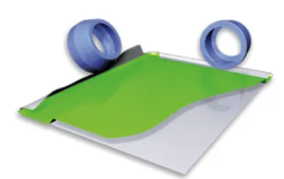
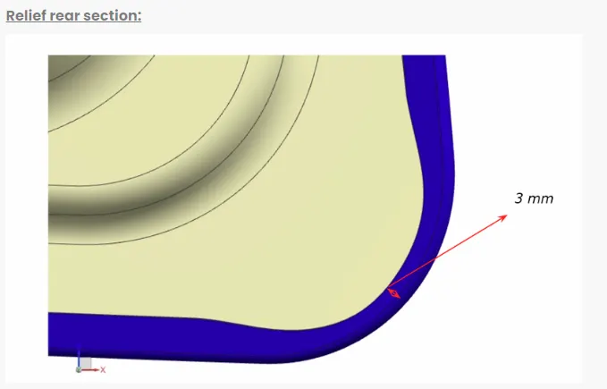
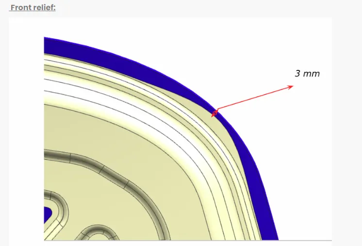
A corner reliefs are provided at the edges of hemmed part to provide corner reliefs.
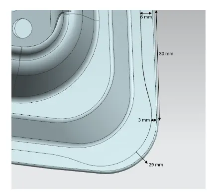
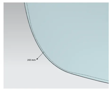
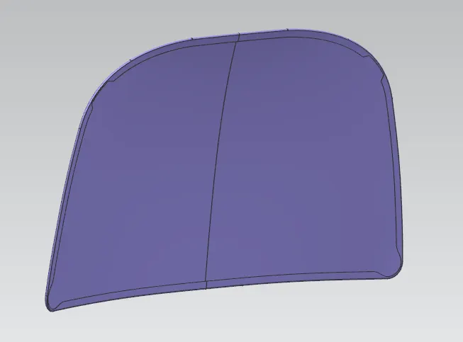
Given outer panel data :
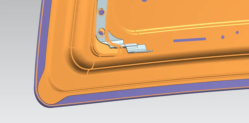
FINAL HOOD MODEL DESIGN
Please find below attached files for your reference.