Hood design-Week 2
Hood design Report:-
Objective
Design hood outer panel, inner panel and reinforcements with the given outer hood skin, master section and design parameters.
Hood:-In simple words, the hood of the car is responsible for the safety of the car. All engine parts and radiators of the car are protected by the hood or bonnet. Car hoods are also used in sports cars as an aerodynamic mechanism by reducing the Air effect. Car hoods provide relatively easy access to the engines in case any maintenance is required.
Design parameters
Hood Thickness Information
Outer Panel Thickness = 0.75mm
Inner Panel Thickness = 0.75mm
Reinforcement Thickness = 1.5mm
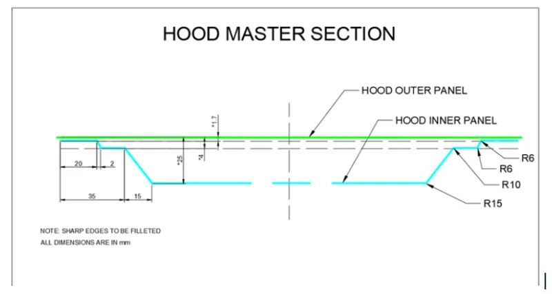
Hood Components:-
- Inner panel
- Outer panel
- Hinge
- Striker
- Reinforcement
Components
1.Hood outer panel:-
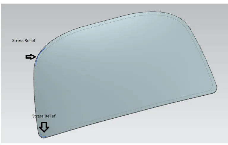
Outer panels are the aesthetic elements of a car. It is the styling team who provides the skin for the outer panel. The shape, position and size of the hood should satisfy the safety norms. So while designing the hood we should give more importance to pedestrian safety. The outer panel is attached to the inner panel by hemming. So, it is necessary to provide required hemming flange and reliefs for the hemming operation. We also provide mastic sealants between the outer panel and inner panel to reduce vibration.
2.Hood inner panel
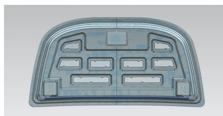
Inner panel is the part that gives strength and rigidity to the outer panel. The master section represents the initial emboss shape and size. Then we provide the emboss for the latch and hinge elements after fixing the location.
3.Reinforcement
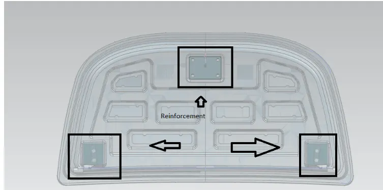
Reinforcements are provided according to the design requirements. Mainly it is provided at the hinge and latch regions to improve the strength locally. Usually the thickness of reinforcements will be higher than that of the inner panels and the value varies according to cost and requirement. According to the design requirement here it is given 1.5mm thickness to both hinge and latch reinforcements.
Latch Trajectory
Latch trajectory is given by the circle drawn from the hinge axis point. Hinge axis point is the center point of the hinge axis. First, we can fix either the latch or the hinge. If we have fixed the hinge position then we should plot the Trajectory circle for the latch. For proper mating condition the striker axis through the tip of the striker should be tangential to the latch trajectory.
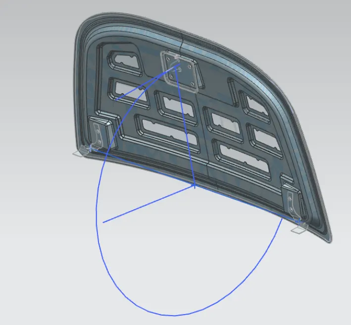
Emboss definitions
Throughout the inner panel we provide different embossed. We can increase the stiffness of the inner panel through these embossed. The shape and size of the embosses also determines the direction of the force distribution resulting from frontal collision. The force should be always distributed away from the passengers.The embosses are designed in such a way that the force is directed to either sides of the car.
Mastic Data
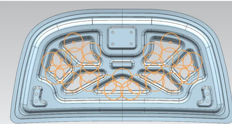
Hoods commonly possess large surface area and hemming can only be provided through its boundary. We cannot use other joining techniques like welding, riveting etc because they leave marks on the outer panel which spoil its aesthetic appearance. So, mastic sealants are used to stick the inner surfaces of the outer panel and inner panel. Mastic sealants are elastic compounds that behave like rubber. It is applied between the inner and outer panels at specified spots. Each spot of mastic sealants has its effect around a circular region of 80mm diameter. Thus, the mastic points are arranged in such a way that it covers the areas away from the hemming which are more vulnerable to vibrate.
Deep Drawing
Deep drawing is one of the most widely used processes in sheet metal forming. Apart from its use in many other sectors, it is applied in the automotive industry for the manufacturing of car body parts. The deep drawing process is a forming process which occurs under a combination of tensile and compressive conditions.
Sheet metal blank is radially drawn into a forming die by the mechanical action of a punch. It is thus a shape transformation process with material retention. The process is considered "deep" drawing when the depth of the drawn part exceeds its diameter. This is achieved by redrawing the part through a series of dies. The flange region (sheet metal in the die shoulder area) experiences a radial drawing stress and a tangential compressive stress due to the material retention property. These compressive stresses (hoop stresses) result in flange wrinkles. Wrinkles can be prevented by using a blank holder, the function of which is to facilitate controlled material flow into the die radius.
Hemming
Hemming is a forming operation in which the edges of the sheet are folded or folded over another part in order to achieve a tight fit. Normally hemming operations are used to connect parts together, to improve the appearance of a part and to reinforce part edges.
In car part production, hemming is used in assembly as a secondary operation after deep drawing, trimming and flanging operations to join two sheet metal parts (outer and inner) together. Typical parts for this type of assembly are hoods, doors, trunk lids and fenders.
The accuracy of the hemming operation is very important since it affects the appearance of the surface and surface quality. Material deformations, which occur during the hemming process, can lead to dimensional variations and other defects in parts. Typical hemming defects are splits or wrinkles in the flange, material overlaps in the corner areas or material roll-in. This is why it is important to provide required reliefs at the corners.
There are two types of hemming operations,
- Conventional die hemming
In conventional die hemming, the flange is folded over the entire length with a hemming tool.
- Roll hemming
It is the roll hemming process that is used for automotive sheet metals. Roll hemming is carried out incrementally with a hemming roller. An industrial robot guides the hemming roller and forms the flange. Roll hemming operation can also be divided into several pre-hemming and final hemming process steps. Roll hemming is very flexible to use and tool costs are significantly lower as compared to those of conventional die hemming. However, the cycle times are much higher since the hemming is realized using a hemming roller which follows a defined path.