Hood design-Week 2
HOOD DESIGN
Introduction
Hood is main component of a car at the front portion. It is used to decorate the car & add luxurious look. The shape of the bonnet is made aerodynamic in order to minimize the air effect.
Design Considerations in Hood
While designing a hood several design parameters are to consider such as the opening angle of the hood, Support system for the hood, Pedestrian safety rules, etc.
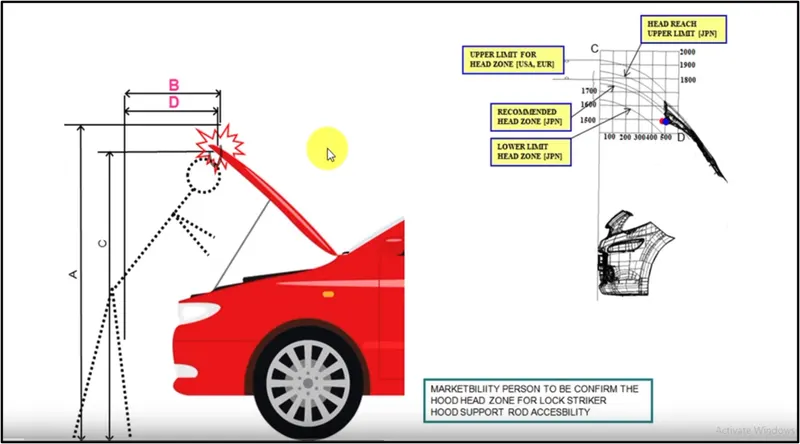
Hood head zone for striker locking: While designing the hood this parameter should be taken into consideration because when we open the hood to get access to the engine compartment to perform any operation while the hood is in open condition the minimum height of the hood should be such that it does not collide or hit to head of the person who is operating. So, the height of hood in open conditions should be more than the average height of humans in that region thereby no human gets hurt.
Hood Stay
This is the support system for the hood as when we open hood we need it to rest to keep it in open position & this can be done by placing it over something or by providing support to it. While designing this one should keep in mind that the support system should be self-sustainable to take the load of the hood even if any external force is been applied on it due to wind or any other reason & it should facilitate easy opening and closing of hood.
This can be done by using two ways
1. Support Rod
2. Gas stay
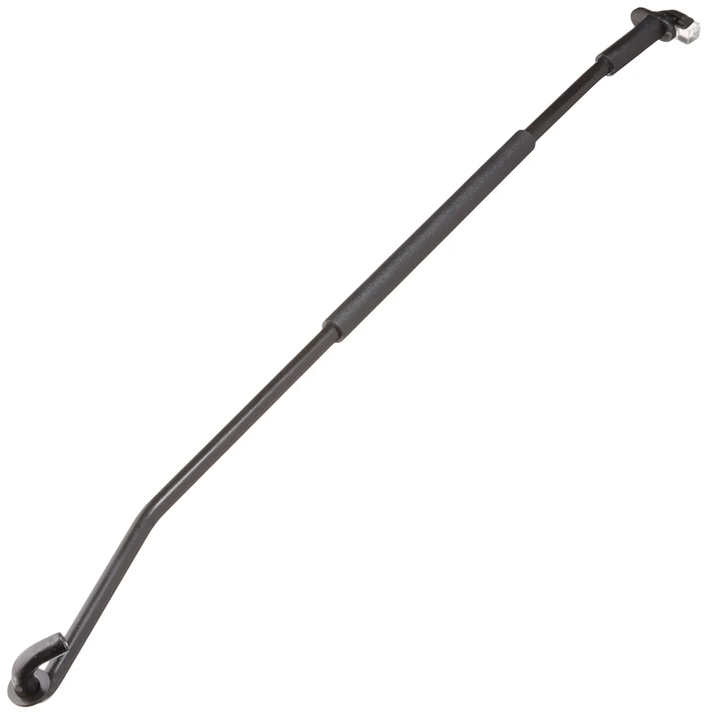
Support Rod: It is a rod that accommodates itself easily inside the engine compartment and support the hood when we open it by attaching the rod in the hook provided inside the hood. Initial bends are been provided to the support rod to provide stiffness.
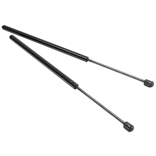
Gas Stay: This type of apparatus is used in most heavy vehicles where the weight of the hood is more and it is difficult for a human being to open it conveniently. So, basically, a gas stay system uses gas-filled telescopic cylinders which only require an initial force to set it in motion.
Pedestrian safety
While designing the hood, it is vital to consider the safety of pedestrians as when your car hits the pedestrian during a crash, it is very important to study the areas over the hood where different body parts of pedestrians are going to hit. we should also take into account the average height of adults and children while designing our hood. So, whenever a new car is been launched, all these safety parameters are checked by taking a crash test and studying the data obtained from it to make changes accordingly to follow pedestrian safety.
Force Distribution
A good designer should always consider the safety parameters as a top priority, In the case of hood design, one should design the hood in such a manner that if the vehicle gets a frontal crash then all the forces must be distributed towards the hinge of the hood, as it is important to reduce the impact of the crash by diverting the force towards the hinges and thus safeguard the passengers in the vehicle.
manufacturing operation
1. stamping
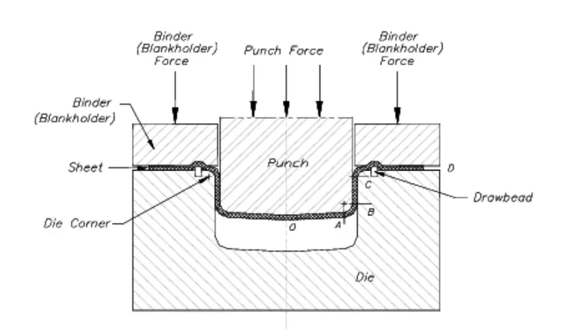
Sheet Metal stamping is a cold-forming process that uses dies and stamping pressing machines to shape sheet metal into various forms. Pieces of flat sheet metal typically referred to as blanks, are fed into a sheet metal stamping press that uses a tool and dies surface to transform the metal into a new shape. The material is placed to be stamped between die sections, where the use of pressure will form and shear the material into the desired final shape for the product or component.
Stamping operations are suitable for both short or long production runs, and be conducted with other metal forming operations, and may consist of one or more of a series of more specific processes or techniques that we will mention below.
With stamping presses built to handle capacities up to 440 tons and precision stamping dies and tooling that we make in-house, we can create parts as thin as 0.005” while maintaining tolerances that often exceed industry standards.
Basic techniques of Sheet Metal Stamping
Metal stamping machines may do more than just stamping; they can cast, punch, cut, and shape metal sheets. Machines can be programmed or computer numerically controlled (CNC) to offer high precision and repeatability for each stamped piece. Electrical discharge machining (EDM) and computer-aided design (CAD) programs ensure accuracy
Blanking
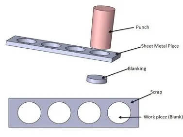
Blanking is a steel manufacturing process in which a flat, geometric shape (or “blank”) is created by feeding a coil of sheet metal into a press and die. The blank is punched out from a large metal sheet in this process. Here’s a graphic representation of the process
Piercing
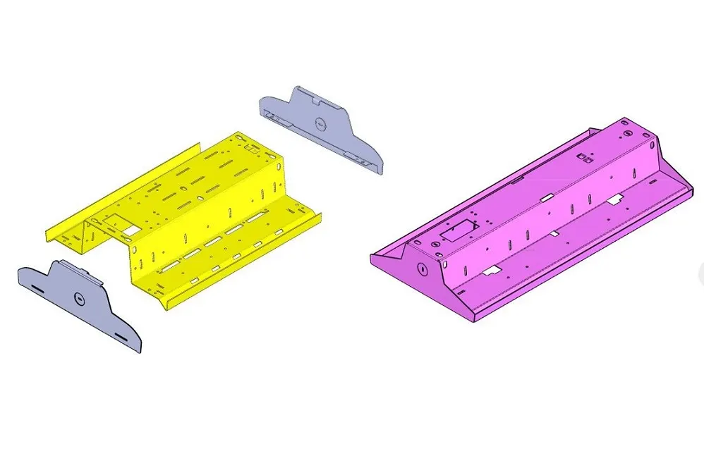
If a part requires slots, holes, or other cutouts, piercing can be employed. Piercing, which can be performed simultaneously with blanking, punches the requisite shapes out of the metal sheet.
Punching
CNC punching is an important option for generating sheet metal blanks. Punching is an inherently faster operation that lends itself to metal fabrications that have many similar features or where there is a higher volume of parts per run.
Embossing
Metal embossing is used to impart a design upon metal sheets. The metal is pushed with an embossing tool or stylus to create a raised effect on the opposite side. By placing the metal sheet on a rubber or foam pad, the positive impression has a smooth surface that will shine or can take pigment.
Bending
Bending refers to the general technique of forming metal into desired shapes such as L, U, or V-shaped profiles. The bending process for metal results in a plastic deformation that stresses above the yield point but below the tensile strength. Bending typically occurs around a single axis.
When you are designing the bends into your stamping metal part, it is important to allow for enough material — make sure to design your part and its blank so that there is enough material to perform the bend. Some important factors to remember:
- If a bend is made too close to the hole, it can become deformed.
- Notches and tabs and slots should be designed with widths that are at least 1.5x the thickness of the material. If made any smaller, they can be difficult to create due to the force exerted on punches, causing them to break.
- Every corner in your blank design should have a radius that is at least half of the material thickness.
- To minimize instances and severity of burrs, avoid sharp corners and complex cutouts when possible. When such factors cannot be avoided, be sure to note burr direction in your design so they can be considered during stamping
Coining
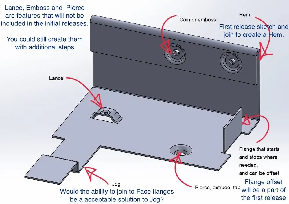
Coining is a bending technique wherein the workpiece is stamped while placed between a die and the punch or press. This action causes the punch tip to penetrate the metal and results in accurate, repeatable bends. The deep penetration also relieves internal stresses in the metal workpiece, resulting in no spring-back effects.
Flanging
Flanging is the process of introducing a flare or flange onto a metal workpiece through the use of dies, presses, or specialized flanging machinery.
Sheet Metal Hemming
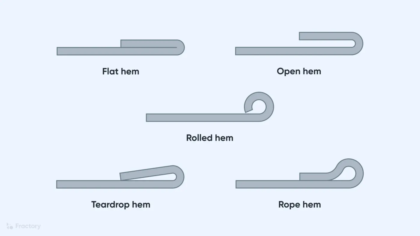
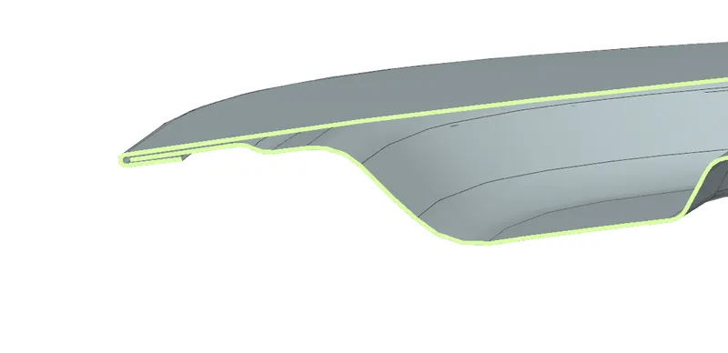
Hemming in sheet metal operations refers to the bending of a sheet metal edge onto itself. It is very similar to edge stitching in clothes. Similar to how an edge stitch strengthens the edge and makes it more durable, a hem imparts strength to the metal edge and improves its appearance. The edge of one part may also be folded onto another part to create a joint.
There are two types of heming process use:
- Conventional die Heming
- Roll Heming
Conventional die heming
Conventional die hemming is suitable for mass production. In die hemming, the flange is folded over the entire length with a hemming tool. Normally the actual hemming is a result of a forming operation in which the flange is formed with a hemming tool after the drawing and trimming operations have been completed. Production plants for conventional die hemming are very expensive, but the cycle times are very low.
Roll Heming:
Roll hemming is carried out incrementally with a hemming roller. An industrial robot guides the hemming roller and forms the flange. Roll hemming operation can also be divided into several pre-hemming and final hemming process steps. Roll hemming is very flexible to use and tool costs are significantly lower as compared to those of conventional die hemming. However, the cycle times are much higher since the hemming is realized using a hemming roller that follows a defined path.
Custom Sheet Metal Stampings Material Options
- Carbon Steel
- Cold Rolled Steel
- Hot Rolled Steel
- Galvanized Steel
- Stainless Steel
- Aluminum
- Beryllium Copper
- Brass
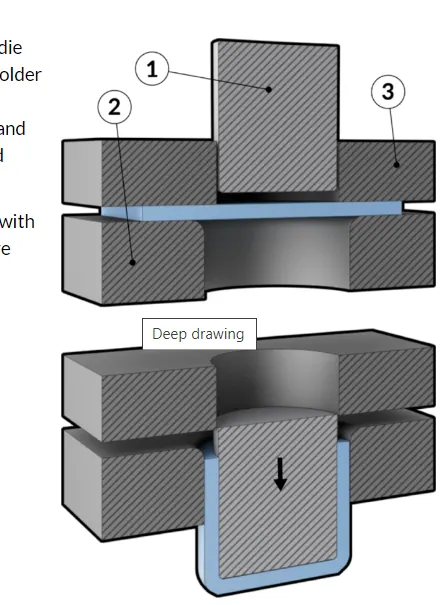
Deep Draw Stamping
Deep drawing involves pulling a sheet metal blank into the die via a punch, forming it into a shape. The method is referred to as “deep drawing” when the depth of the drawn part exceeds its diameter. This type of forming is ideal for creating components that need several series of diameters and is a cost-effective alternative to turning processes, which typically require using up more raw materials. Common applications and products made from deep drawing include:
- Automotive components
- Aircraft parts
- Electronic relays
- Utensils and cookware
Design approch
Inner Panel
- In the inner panel only we can research & implement the safety of pedestrians & as well as the driver. In this panel only we can attach the reinforcement, embossed, mastic points etc.
- It is an object of the present invention to provide a hood inner panel capable of reduction of a reaction force of the hood inner panel even if a level of deformation of a hood of a vehicle increases, & ensuring a sufficient energy absorption capacity.
- lets look the mastersection of inner panel with outer panel and design consideration
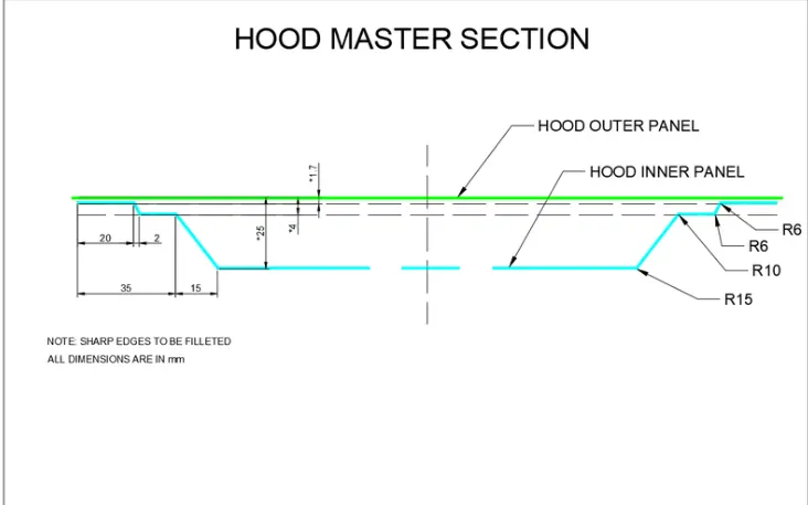
Hood Thickness Information
- Outer Panel Thickness = 0.75mm
- Inner Panel Thickness = 0.75mm
- Reinforcement Thickness = 1.5mm
- according to design consideation we start to design inner panel of hood assembly
- I used to share my command history which used in design
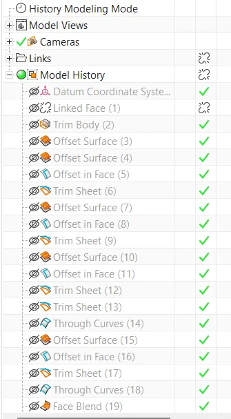
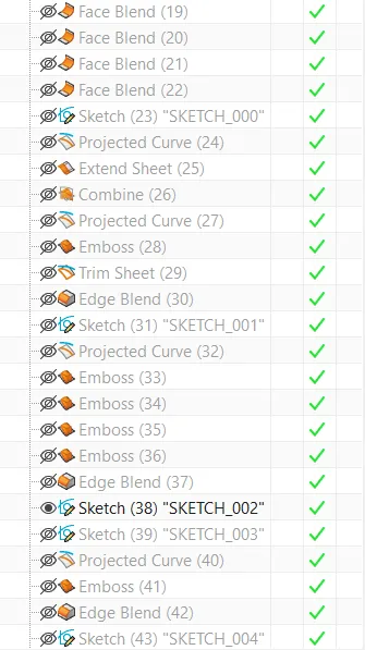
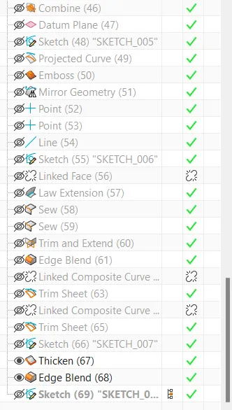
- we first create blend section surface as per design consideration with the help of offset, trim sheet, through curves and face blend comand.
- The next step to create first emboss of inner pannel with 4mm edge blend and then we create second inner emboss
Embossing
- The sheet metal embossing operation is commonly accomplished with a combination of heat & pressure on the sheet metal, depending on what type of embossing is required.
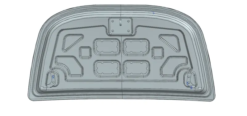
- The inner panel consists of various embosses which help dissipate the force during impact. The width and depth of the emboss is determined by simulations and analysis to check for failure. These emboss definitions are created at an angle so that they point away from the centre of the hood when viewed from the front of the vehicle.
create mastic points
The mastic points are areas where the mastic is placed to attach the outer panel to the inner panel. We cannot use spot welding as it would give a less aesthetically pleasing result. Hence mastics are used to join the panels together as it does not melt the metal itself.
create hinged mounting with datum plane
- first create datum plane with the help of zx plane according to the distance and angle we want create emboss mounting.
- create a sketch on zx plane to create mounting geometry sketch.
- used projected curves and project curves on surface where we want to create mounting.
- used emboss comand and used datum plane for upto surface of emboss given 5 degree angle of mounting emboss we also used offset from plane as according to our design approch
Latch Trajectory
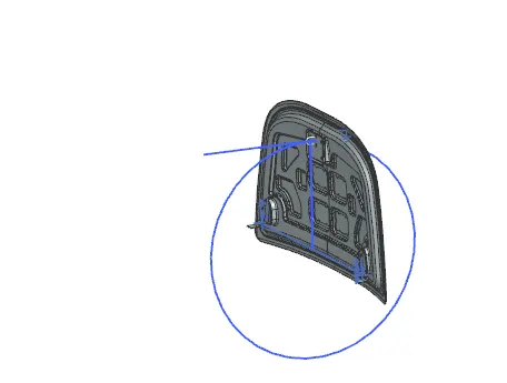
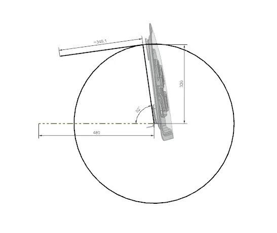
The latch trajectory shows the striker's way when the hood is opened and shut on a vehicle. The range of the round Trajectory is controlled by the set standard dependent on the typical stature of an individual. The range is estimated from the pivot hub up to the Latch. It is the Trajectory on which the movement of the hood (opening and closing are dependent). This circular Trajectory has a radius equal to the length from the centre point of the centre axis of the Hinge to the striker point on Latch. The striker point is also tangent to the Trajectory.
latch mounting
by the help of latch trajectory and wave linker geometry we used to build latch mounting with law extension, sew and trim extend command. we also given assembly constrain. we set the position of latch and mounting according to latch trajectory.
hinged hole
hinged hole we create with the help of position of hinged assembly on hinged mounting in inner pannel. we used wave linked geometry curve and select two hole of hinged.
Thickhen surface
Use the Thicken command to offset one or more connected faces or sheets into a solid body. Thickening occurs by offsetting the selected faces along their face normals, and then creating sidewalls. The Thicken command is similar to the Offset Face command.
we used to here 0.75 thickness of inner pannel.
HINGE PLACEMENT
First hinges are placed on to the embosses and as inner panel is applied with fixed constraint hinge is placed parallel and touch constaint.
Then the hinge is mirrored with assocative connection to other side to get the same hinge position on other side of the inner panel.
LATCH ATTACHMENT
The latch/Striker is position from the basis of hinges centre point.
Two points is marked from the two hinge axis and a line is drawn from the two points.
A midpoint is taken from the line for positioning the latch.
outer panel
commond we used in outer panel
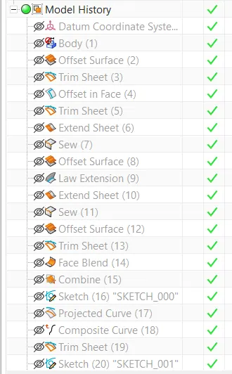
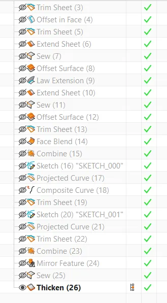
sew command
Sew command to join two or more sheet bodies into a new single sheet body. If the collection of sheet bodies encloses a volume, a solid body is created. The selected sheet bodies must not have any gaps larger than the specified tolerance, or the resulting body will be a sheet body.
law extension command
Law Extension command to extend an existing surface or sheet based on the laws for distance and the angle of the extension. Law Extension creates flanges or extensions when a particular direction is important or when it is necessary to reference the existing face.
projected curve
In the NX Sketch, the projected curves can be created by using the existed objects such as curves, edges, faces, etc.
rear relief and front relief
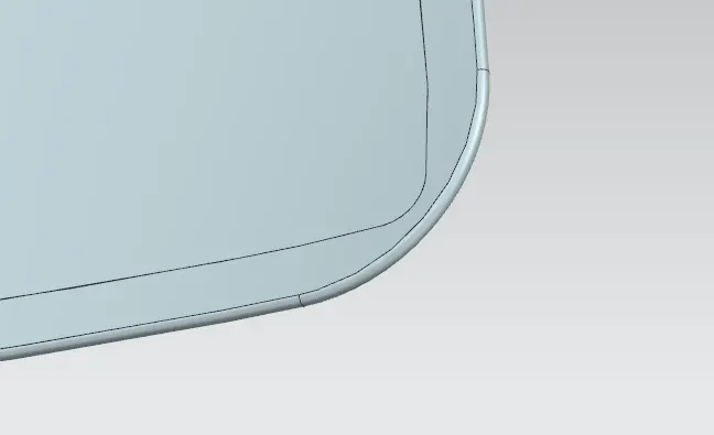
we used 3mm rear relief to given proper hemming to outer pannel
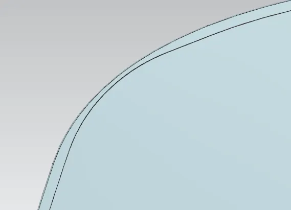
same thing we done with front relief
Reinforcement : Reinforcements are provided according to the design requirements. Mainly it is provided at the hinge and latch regions to improve the strength locally. Usually thickness of reinforcements will be higher than that of the inner panels and the value varies according to cost and requirement. According to the design requirement here it is given 1.5mm thickness to both hinge and latch reinforcements.
we used to create latch and striker reinforcement and hinged reinforcement by wave linker geometry with help of new component and saved the reinforcement file.
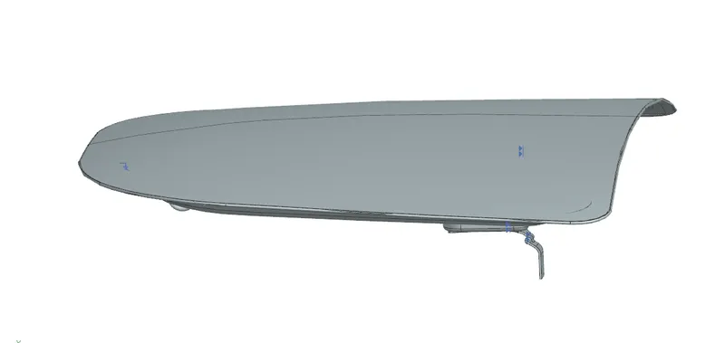
Final Assembly
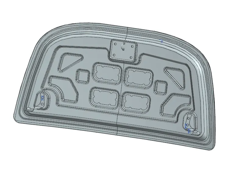
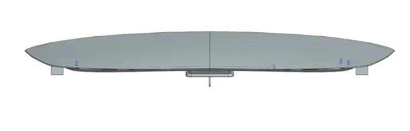
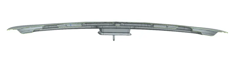
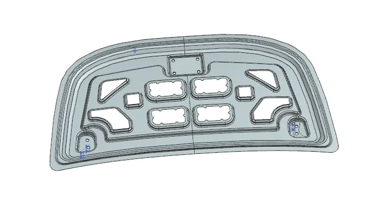
conculsion
I learned to design concept of hood panel in BIW sheet metal design and its assembly to create and follow a proper methodology and design consideration.