Hood Design
Aim: To design the Hood outer panel, inner panel, the necessary reinforcements by following the Master section and creating a proper assembly without violating the design parameters using Siemens NX.
Project Overview:
Hood is the component of the car which is used to cover the engine compartment or the boot. In this project we are going to design the Hood outer panel and inner panel from the given Class-A surface. We will follow the design rules and create the hood assembly as per industry standards. Also we will perform draft analysis on the inner panel and create a section modulus of the entire assembly.
Theory:
Hood:
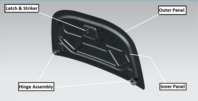
Hood or Bonnet is a hinged cover which is used to cover the engine compartment or the boot. The hood opens which allows us to access these compartments, depending upon the engine placement of the vehicle. The hood assembly has the following components:
- Hood Outer Panel
- Hood Inner Panel
- Latch and Striker
- Hinges
Wrap Around distance:
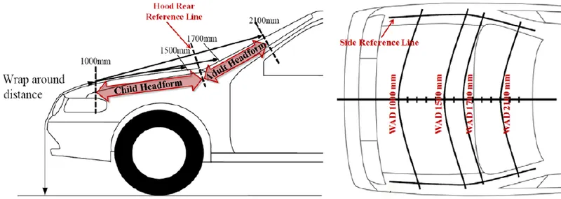
- During any accident scenarios the pedestrians are prone to maximum damage. In order to ensure their safety we have to consider this parameter.
- In accidents the pedestrians are more likely to suffer from head injury. Hence we have to design the hood inner panel with less stiffness and pedestrian friendly considerations.
- The wrap around distance is the distance from the ground to the head impact zone on the hood, around the car when observed from the side view.
- The Impact zones are categorized into two types: Adult Impact Zone & Child Impact Zone
- This distance depends on the average human height of the region for where the car is designed. As per this data the impact zones will be considered and necessary modifications will be made.
Mastic Sealants:
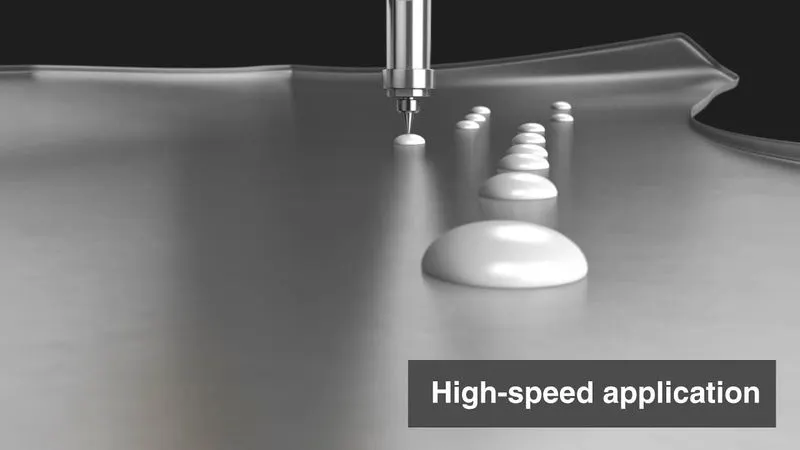
- Mastic sealant is the paste used to join two components.
- Once applied and cooled it hardens, joining the components firmly.
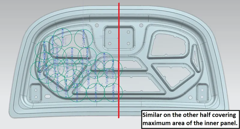
- This paste improves the local strength of the component of about 80 mm diameter. We apply these sealants in such a way that the maximum area of the component is covered.
- In Hood Assembly the mastic sealants are applied between the inner panel and the outer panel.
Source: Youtube- Mastic Sealants
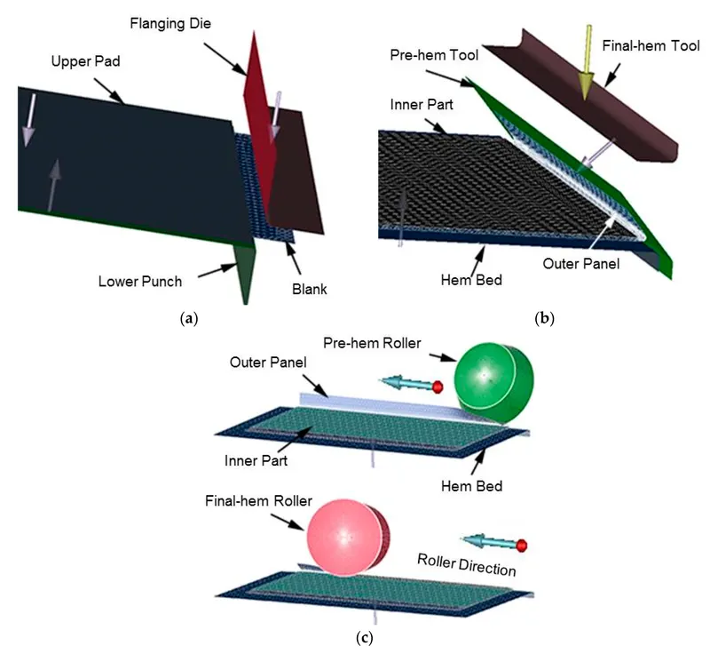
Hemming:
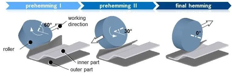
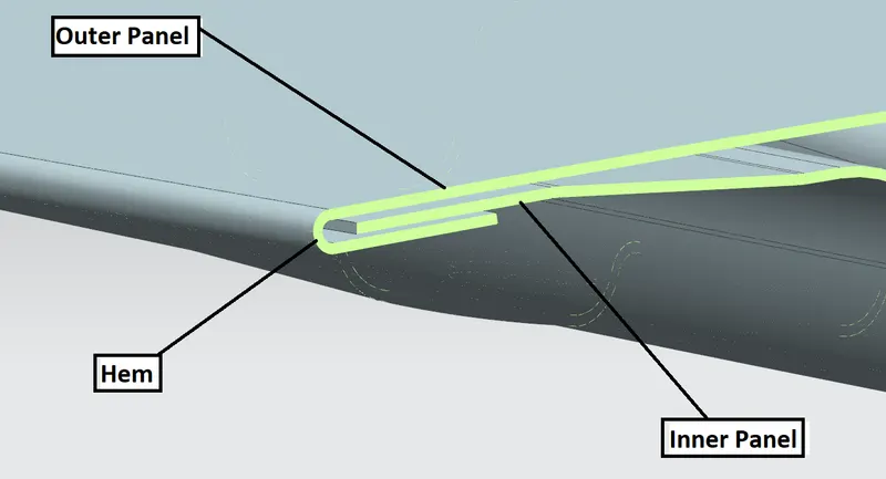
- Hemming is the process in which an extended sheet of one component is wrapped upon an inner component to restrict its degree of freedom.
- In this case the hood outer panel is wrapped around the inner panel using this hemming process.
Source: Internet
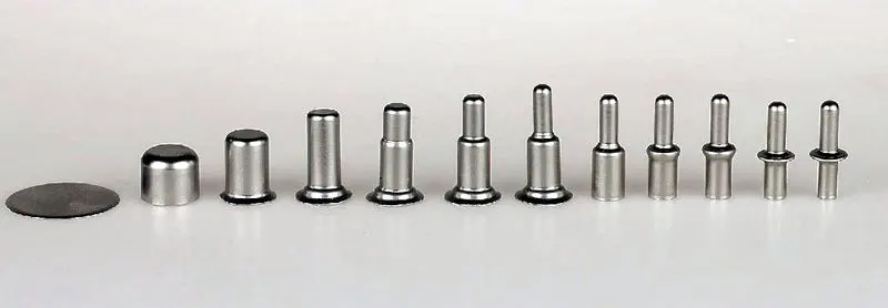
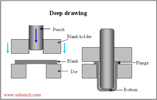
Deep Drawing:
- Drawing is a sheet metal forming process in which a metal sheet is pressed against a die using a punch.
- The deep drawing process is when the same happens but the depth component is drawn more than its diameter.
- Here the diameter of the component decreases as the length to the drawn increases.
Source: Internet
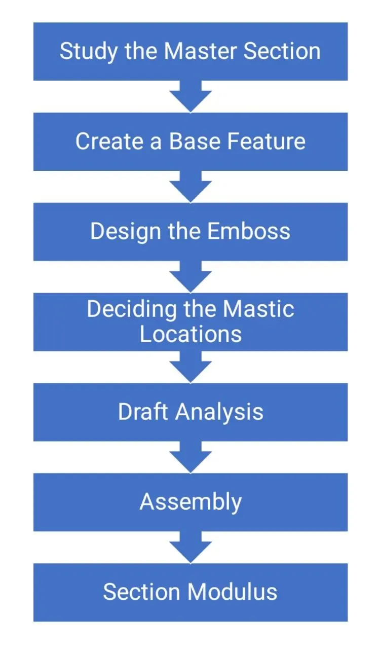
Design Approach:
Procedure:
I] Studying the Master Section:
Master Section:
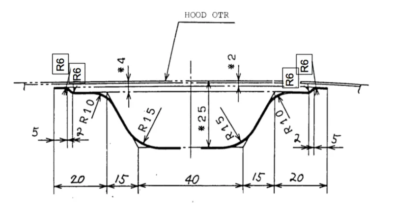
Given Thickness Data:
- Outer Panel Thickness = 0.75 mm
- Inner Panel Thickness = 0.75 mm
- Reinforcement Thickness = 1.5 mm
II] Creating a Base Feature for Inner Panel:
- We have a Class-A surface of the outer panel. Following the master section we offset it to the desired distance.
- Here we would trim the Class-A into two halves and design one half and mirror it later as the Class-A is symmetric.
- Next we offset the surface multiple times as per the master section.
- Later we trim them using the Trim Tool and also provide the bend radii using the Edge Blend or Face Blend tool as per requirement.
- Following these steps we obtain the Base feature for our Hood inner panel.
III] Creating the Emboss on the Inner Panel:
Emboss:
Emboss are the inward projections given on the inner panel or any component. These feature serves two purpose:
- To minimize the distance between the Outer & Inner panel inorder to ease the joining process.
- To divert the impact force away from the passengers so as to ensure their safety.
Procedure to create an emboss:
- Create a basic sketch profile of an emboss to be made.
- Project the emboss profile on the base feature using Project Curve Tool.
- Use the Emboss feature to create the emboss.
- The End Cap of the emboss can be altered as per our requirements. For basic emboss we use the embossed face as an end cap. End cap is nothing but your outward projected face.
NOTE: Draft of about 7 deg to 25 deg should be maintained.
IV] Deciding the Mastic Locations Points:
Understanding How the sealants can be applied:
- The mastic locations can be designed in various ways.
- We can simply provide a patch where the mastic sealants will be applied such that the local strength of 80 mm diameter covers the maximum area of the hood.
- Also we sometimes provide a Bead or Dimple in which the sealants are filled.
Procedure:
- Create a basic profile of the patch.
- Project the profile on the base feature using Project Curve Tool.
- Use the Trim Sheet Tool to remove the unnecessary material in order to generate desired results.
V] Creating the Emboss on the Inner Panel for Hinge Mounting:
- Create a basic sketch profile of an emboss to be made.
- Project the emboss profile on the base feature using Project Curve Tool.
- Use the Emboss feature to create the emboss.
- The End Cap of the emboss can be altered as per our requirements. For Hinge emboss we use a datum plane as an End Cap. End cap is nothing but your outward projected face. Assigning the end cap we assign the orientation of the Emboss(Flat or Curved).
- To Create a Datum Plane, first create an offset plane.
- Secondly rotate it at a certain angle as per the requirement.
- Use this datum plane as an end cap.
NOTE: Draft of about 7 deg to 25 deg should be maintained.
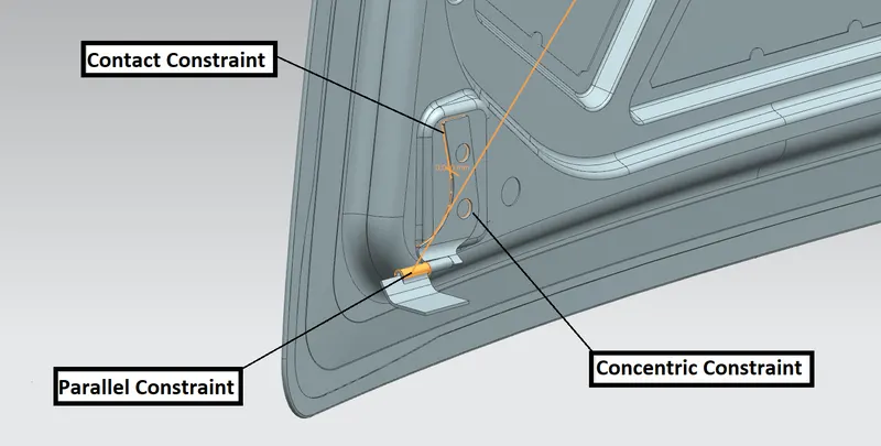
VI] Hinge Mounting:
- Constraint the hinge axis with the X-Axis by applying Parallel Constraint.
- Make the face of Hinge and Emboss coincident using Coincident Constraint.
- Also make the Holes concentric with help of Concentric Constraint.
- Lastly Mirror the entire Hinge Assembly about the symmetric plane ensuring that the mirrored part is associative.
VII] Creating the Latch Trajectory:
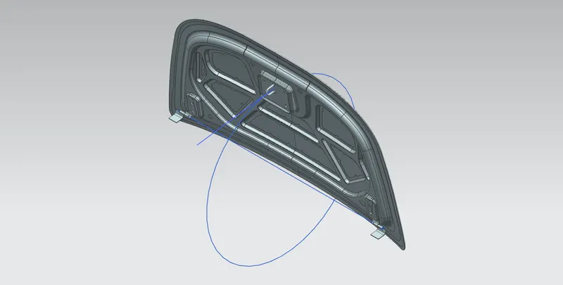
Before understanding the Latch Trajectory let's take a look at the procedure for creating this geometry.
Procedure For Creating the Trajectory Geometry:
- Create two points on both the Hinge assembly on the hinge axis.
- Join these two points using a Line.
- Create a Circle at its midpoint and on the symmetry plane.
- Also create a tangent line to the Circle.
Latch Trajectory
- Latch Trajectory is the path on which is followed by the Hood during its opening and closing.
- Here the Circle represents the trajectory.
- The Line drawn represents the Hinge Axis about which the Hood will open and close.
- The tangent line created is to ensure that the latch on the stricker is tangent to the trajectory circle.
VIII] Creating the Striker Emboss:
- Create a basic sketch profile of an emboss to be made.
- Project the emboss profile on the base feature using Project Curve Tool.
- Use the Emboss feature to create the emboss.
- The End Cap of the emboss can be altered as per our requirements. For Striker emboss we use a reference surface as an End Cap. End cap is nothing but your outward projected face. Assigning the end cap we assign the orientation of the Emboss(Flat or Curved).
- To Create a reference surface, we use Wave Geometry Linker.
- This Tool provides us the feature to link any geometry from one part to another part / assembly.
- Take the back surface of the Striker as a parent face and extract it to the Inner Panel part file.
- Use this surface as an end cap.
NOTE: Draft of about 7 deg to 25 deg should be maintained.
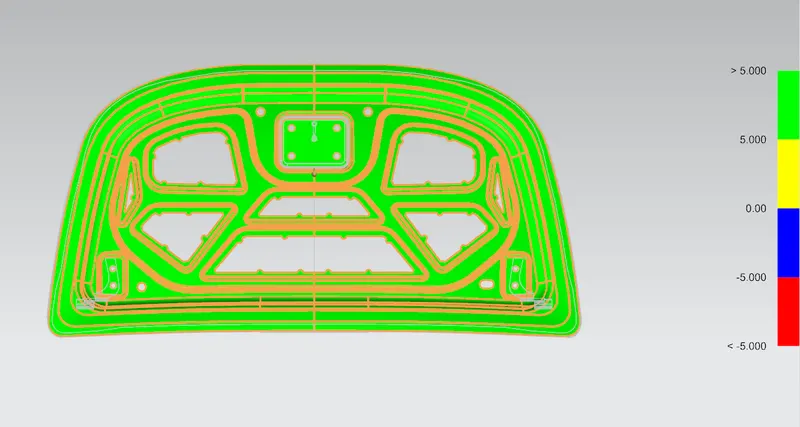
IX] Draft Analysis of Inner Panel:
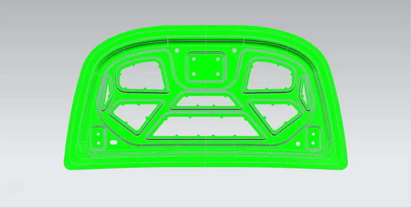
- Draft analysis is performed on the sheet metal component to ensure that there are no undercuts / negative drafts on the component.
- If there are any of these negative drafts the component is not manufacturable.
- This Analysis is performed by the design engineers which helps in eliminating major defects / errors at the very beginning of any product design.
- The Draft of about 7 deg to 25 deg is given on the Sheet Metal Components.
Procedure to perform draft analysis:
- Create a datum coordinate system on the flat surface.
- Check the Deep drawing angle.
- Open the Draft Analysis Tool.
- Select the Perpendicular axis to the flat surface from the newly formed CS.
- Select the component on which we have to perform the draft analysis. ( Inner panel in this case )
- Click on Ok to obtain the results.
NOTE:
- Maximum portion should be Green as per the color code shown on the RHS of the screen.
- In some cases Yellow patches are accepted but it is a good practice to try to eliminate these patches.
- There should be no Blue or Red patch on the component.
X] Hemming on Outer Panel:
Procedure:
- Extract the boundary of the Class-A surface and create a law extension surface perpendicular or at angle to the Class-A as per requirement.
- Offset this surface at about 15-20 mm as it is the effective hemming length.
- Offset the Class-A below considering the thickness of the Outer panel, inner panel, and hem clearance of about 0.2 mm between the components.
- Trim this surface with the law extension surface.
- Trim the Class-A, lower offset surface and the original law extension surface together to remove excess material.
- Later provide Face Blend using 3-Face Blend Feature to generate the Hem.
NOTE: We provide corner relief to the corners. This is given so as to avoid tearing of the sheet during the rolling step of hemming.
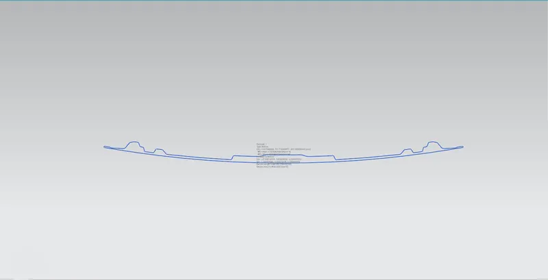
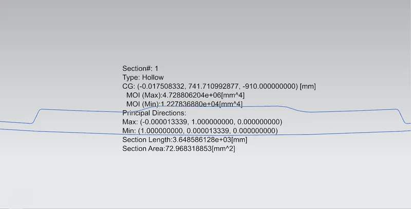
XI] Section Modulus :
- Create a Datum Plane passing through the Assembly
- Using the Intersection Curve Tool create an intersection curve of the assembly
- Project this curve in a sketch and create a continuous outer curve from the projected one.
- Lastly use the Section Inertia Analysis Tool to obtain the results.
Results:
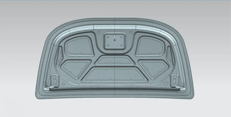
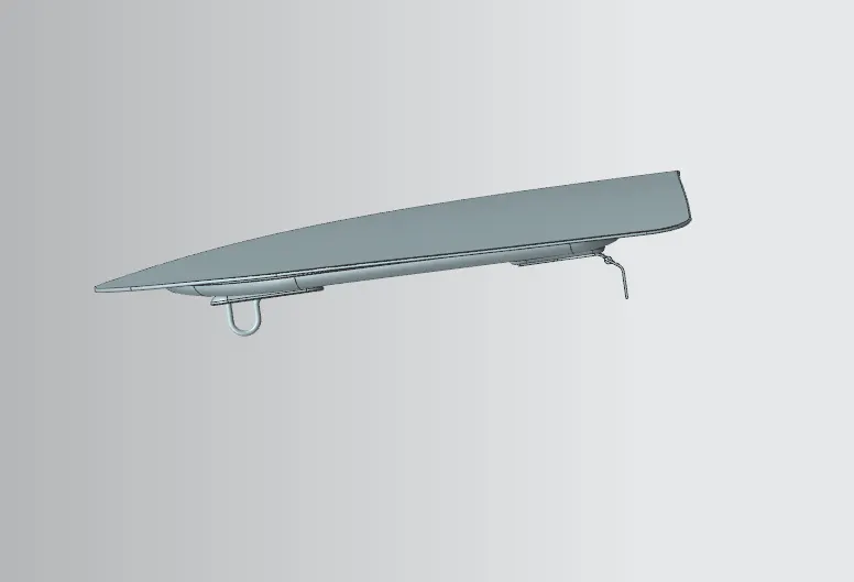
Component Formed:
Front View:
Side View:
Draft Analysis:
Section Modulus:
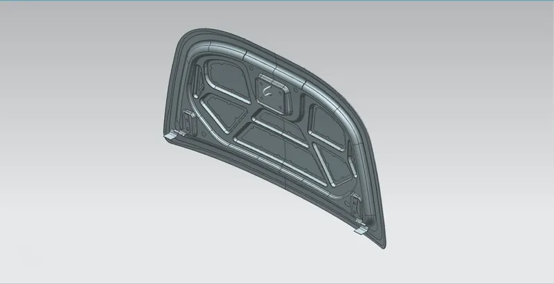
Isometric View:
Conclusion:
Hence we have successfully completed the design of Hood Assembly by following proper industry standards and design rules using the Siemens NX.