Hood design-Week 2
HOOD DESIGN
Aim: To create an ASSEMBLY of Hood Inner Panel, Outer Panel, Latch, Hinge and the Reinforcements by following the Master section using the various design criterion.
Introduction: Hood or bonnet is the hinged cover located at the front of the motor vehicles that is used to access the engine compartment. Hood assembly consists of different parts that combine to be used in a vehicle. Various parts of the hood are:
- Outer panel
- Inner panel
- Hinges
- Latch & Striker Mechanism
Its purpose is to provide access to the engine for repair and maintenance. A concealed latch is used to hold down the hood. Hood sometimes also contains a hood scoop and wiper jets. Car hoods are typically constructed from steel and sometimes from aluminum.. The hood design may vary from one model to another and also as per the customer specifications.
For repairs and maintenance, the components covered by Hood can be accessed by the following two methods
- Support Rod
- Gas Stay
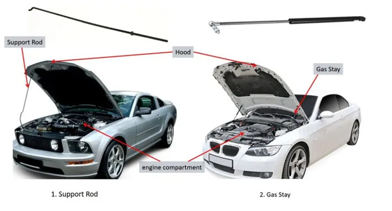
fig .1
Reinforcement & Design requirements for Car Hood
- Hood Head zone for lock striker: In the fig .2 shows Hood Head zone for lock striker
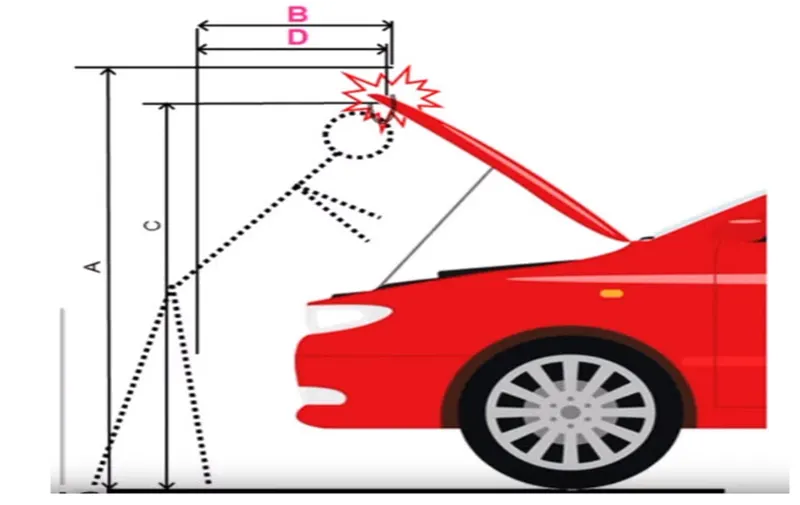
fig .2
The opening angle of hood will give A, C, B and D with respect to the ground. These A, B, C & D are decided in the head impact zone. Opening angle varies from region to region depending on average human height. Depending on the average height of persons in a country hood opening angle is decided.
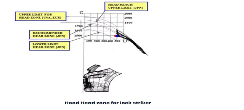
fig .3
From the hood opening angle data, Support rod or Gas stay is designed. The position of Support rod is on the other side of the battery.
- Adding latches and stiffener pad: Latches are secured on the inner panel. Its primary function is to keep the inner panel attached to the vehicle body. To attach Hinges and striker mechanism to the inner panel, holes are punched which are makes the inner panel weak at these zones. To reduce the stress concentration we use stiffener pads along with fasteners.
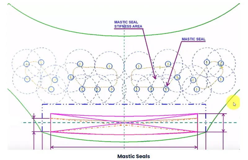
- Mastic Seals: Mastic Seals are sand witched between Inner and outer panel to reduce Noise, vibration, and harshness. Every mastic will have an effective area is equivalent to80mm dia. Circle area locally. Inner and outer panel gap ranges from 2 to 5mm. In our case it is around 5.5mm.
- Emboss definition: Emboss are provided in the inner panel of the hood assembly. This increases the stiffness of the inner panel and hence the bending strength. This helps in weight reduction of the hood and also to dissipate the force during collision as well. These embosses directs the force towards the hinges of the hood.
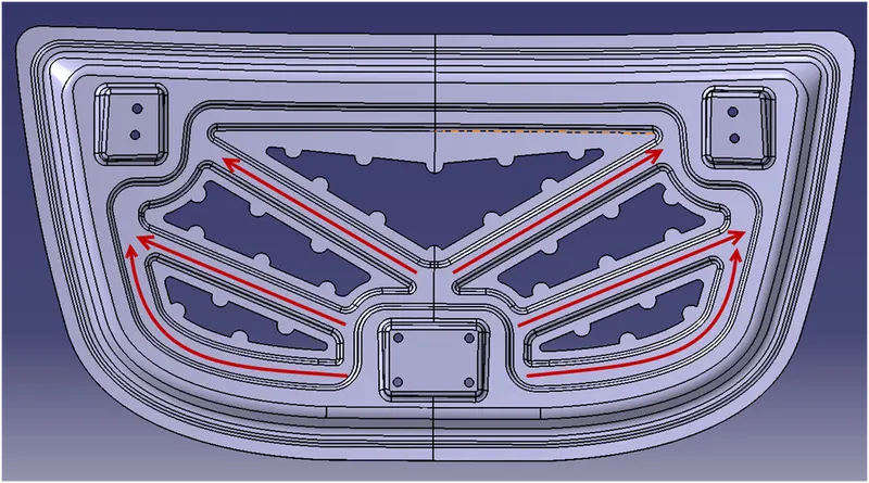
fig.5 Force dissipation directions
- Deep Drawing: Deep drawing is a sheet metal forming process in which a sheet metal blank is drawn into a forming die by a punch. It is a shape transformation process. The process is considered "deep" drawing when the depth of the drawn part exceeds its diameter.
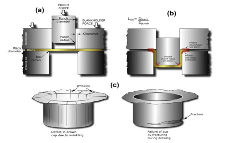
fig.6
- Hemming: Hemming is a forming operation in which the edges of the metallic sheet are folded or folded over another. Normally hemming operations are used to connect parts together, to improve the appearance of a part and / or to reinforce part edges.
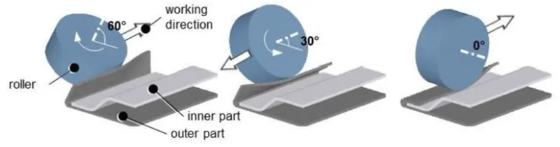
fig.7
- Hood for Better Pedestrian Rating:
- Inlaid Hood: The line which is drawn 45 deg. from ground to Side Reference of car and which is meeting point on fender is called Inlaid Hood.
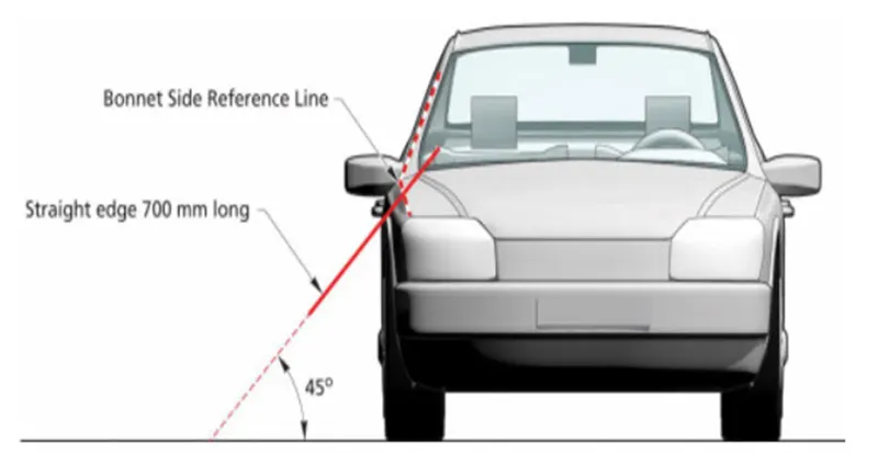
fig.8
- Wrap around Hood: The line which is drawn 30 deg. from ground to front surface of the Hood and that meets at a point on the outer panel is called wrap around Hood.
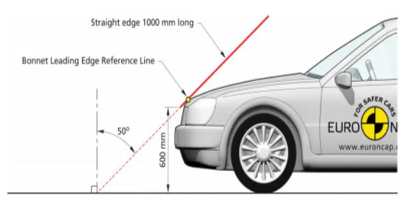
fig.9
Depending on the Inlaid Hood & Wrap around Hood design criteria we can design hood to decide head impact zone for minimal injury to the pedestrian.
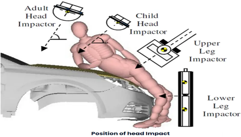
fig.10
Above fig. shows the position of head impact. From this we can decide the position of embosses and cutouts.
Design Procedure
- Import the file: File > open > browse file and select the given file in assembly design work bench.
a. Inner Panel Design:
We have to design Inner and outer panel by using given class-A surface as well as given master section.
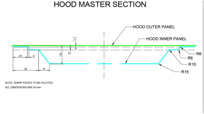
fig.11
From the master section we created the offsets of the given Class-A surface to create embosses.
Create a boundary around the given surface and use parallel curve offset boundary line.
Use split command to create the offset surface
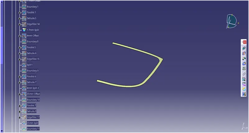
fig.12
Repeat the steps as per the given master section
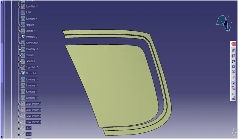
fig.13
Use multi section feature to join these offset surfaces and fillet the edges
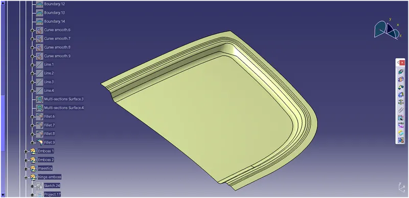
fig.14
Create embosses, a draft of 10 degrees has been used in sweep command. Create cutouts to save the material and create mastic circles.
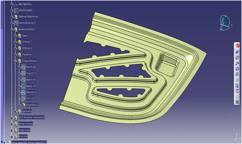
fig.15
Create the other half using symmetry feature and join them.
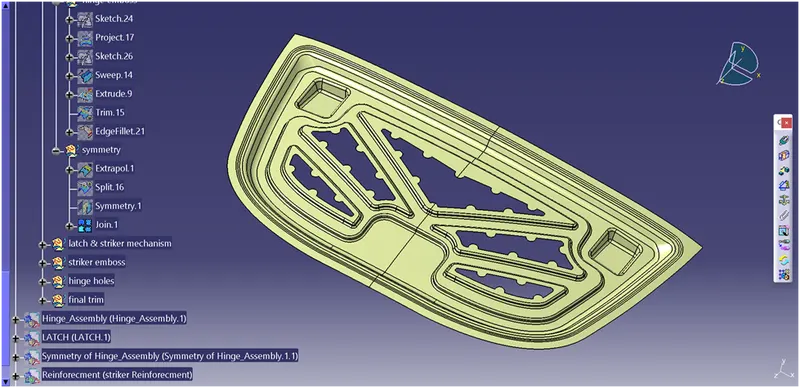
fig.16
In order to place the latch and striker mechanism we need to find out the trajectory of the striker and then accordingly we create emboss for the placement of this striker. Before this we need to ensure that the hinge axis is parallel to a plane so that no stress occurs on the panel due to hinges. The centre of the trajectory circle must be the midpoint of the axis of hinges.
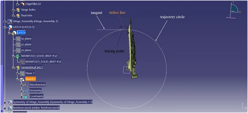
fig.17
In part design work bench, use a thick surface option to make sheet metal part, here 0.75mm is the thickness of the both the panels.
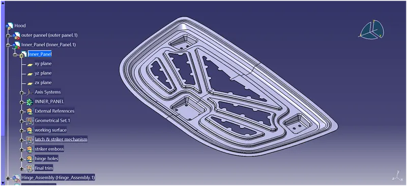
fig.18
Similarly we can design outer panel using given data and provide reinforcement at the required positions.
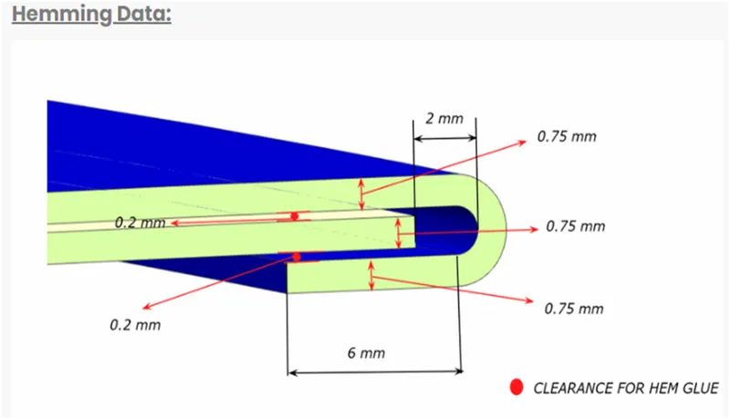
fig.18 Hemming data given for outer panel
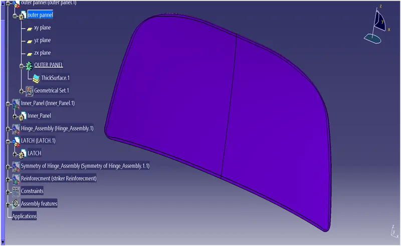
fig.19 Outer panel
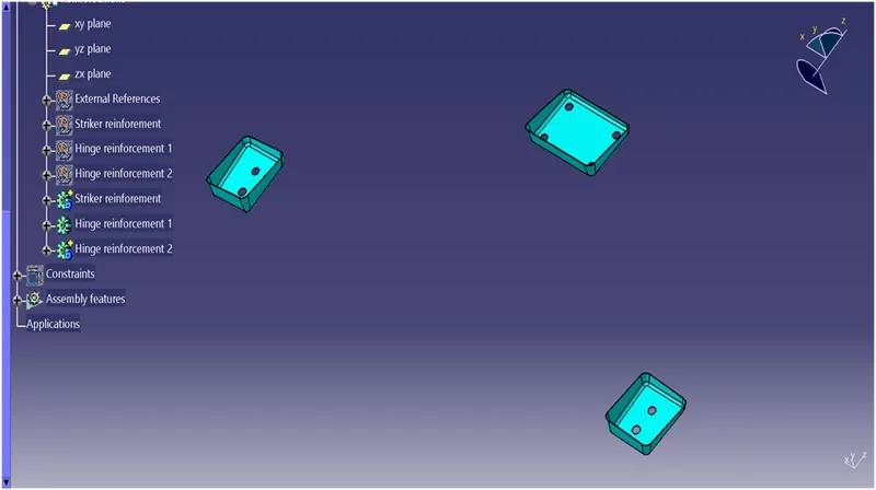
fig.20 Reinforcements
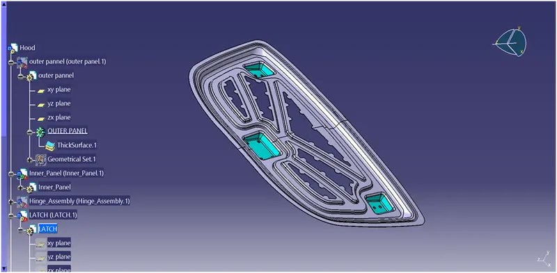
fig.20 Hinge and striker reinforcements
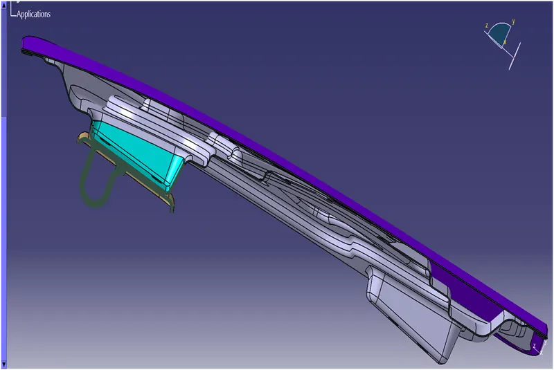
fig.21 Sectional view of hood
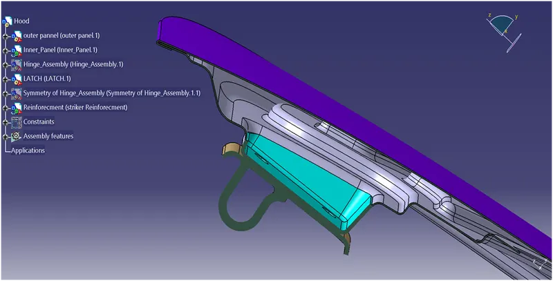
fig.22 Detailed section view of hood
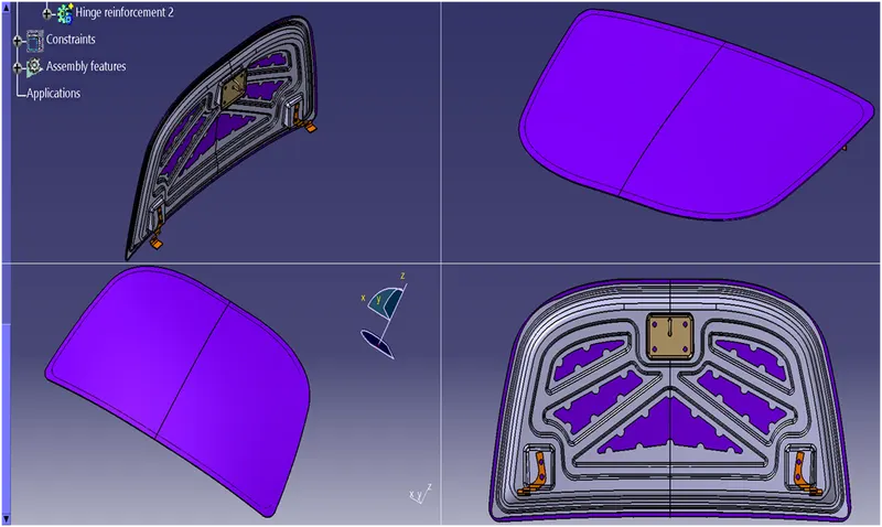
fig.23 Views in different orientations
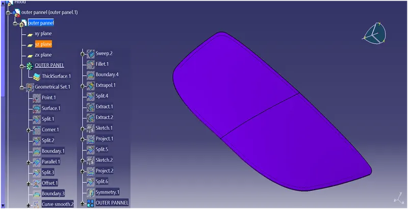
fig.24 Outer panel command features used
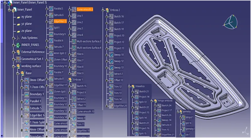
fig.25 Inner panel command features used
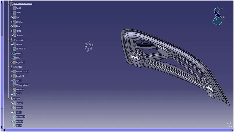
fig.26 Inner panel command features used
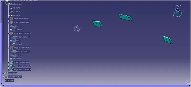
fig.27 Reinforcements command features used