Hood design-Week 2
Aim
A detailed report about the Hood Design which includes a detailed explanation about hood and its
components, Latch Trajectory, Mastic Data, Emboss Definitions, Manufacturing process like DeepDrawing and Hemming, and all the parameters followed in the design and To Submit an ASSEMBLY
of Hood Inner Panel, Outer Panel, Latch, Hinge and the Reinforcements.
Styles and materials
On front-engine cars, the hood may be hinged at either the front or the rear edge, or in earlier models
(e.g., the Ford Model T) it may be split into two sections, one each side, each hinged along the Centre
line. A further variant combines the bonnet and wheel arches into one section and allows the entire
front bodywork to tilt forwards around a pivot near the front of the vehicle.
Hoods are typically made from the same Material as the rest of the body work. This may include steel,
aluminium, fiberglass or carbon fiber. However, some aftermarket companies produce replacements
for steel hoods in fiberglass or carbon fiber to make the vehicle lighter.
Hood Design
A hood, also referred to as a bonnet in some other countries, is the hinged cover that rests over the
engine of a front-engine vehicle.
The hood of a vehicle is the metal panel that covers the engine. It is usually located at the front of the
car, and it opens to provide access to the engine compartment. The hood is an important safety
feature, as it helps to protect passengers from being injured by the engine in the event of a collision. In
addition, the hood can also help to cool the engine by deflecting heat away from the cabin. For these
reasons, it is important to ensure that the hood is in good condition and properly secured before
driving. Not only does the car’s hood protect the engine from the elements, but it also helps to
improve the car’s aerodynamics. But perhaps the most important use for the hood is as a safety
feature. In the event of a collision, the hood can help to absorb some impacts and reduce the risk of
serious injury. As a result, it is essential to keep the hood in good condition and to replace it if it is
damaged. Hood are typically made out of steel or aluminium, although aftermarket manufacturers
may manufacture hoods out of fiber glass, carbon fiber, or dry carbon. The hood serve as a great deal
of purpose in protecting the passengers inside the car and the pedestrain in the event of an accident
Purpose of Hood:
Its purpose is to provide access to the engine for repair and maintenance.
Components In Hood
The components of hood assembly are :
Hood outer panel - It is the styling metal cover mounted on hood inner panel
Hood inner panel - The inner panel provides the strength to the hood
Hinges - Hinges are used to for opening or closing the hood
Striker - It is used for locking the hood in closed position
Types Of Design Considerations in Hood
There are certain aspects of study in designing a hood such a head collision, Force distribution, Hood
stay, and mainly Pedestrian Safety.
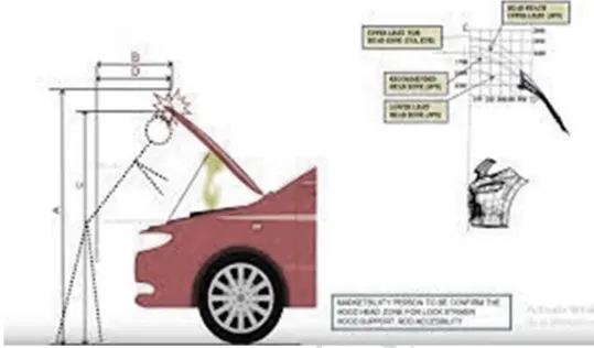
Hood Inclination Angle: During opening and closing of the hood, people must have a space
to look around while cleaning or repairs. For that the hood inclination should be in a way that
doesn’t restrict the people, or else the people will face collision of their head with the hood.
For example, in India the average height of people is around 5ft, while in America, it’s around
5.5-6 ft. So, the angle should be calculated, and the hood should be designed in that manner.
Hood stay: Hood stay is an important part in a vehicle and should be considered while
designing a hood as when the hood is opened it needs to be restricted from closing until we
need it to be closed. There are mainly two types of hood stays that is
Force Distribution: This is one of the safety aspects when designing the hood. It is necessary
for a designer while designing the hood that when the vehicle is hit to a rough area, the force
exerted on to the vehicle should not be transferred directly to passengers, instead the force
should be diverted to the hinges and not directly to the passengers.
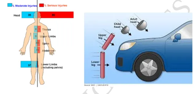
Pedestrian Safety: When designing the hood, the main analysis of the designer in designing
the hood must consider the safety of the pedestrians. These include children to adults. The
hood should be designed in such a manner such that, whenever there will be a collision with
the car to a pedestrian, it is likely to analyze that the head of the pedestrian will strike the
hood first. So, the designer should make sure that the hood is divided into areas in the hood
where the head should be most likely to hit and, in a way, create less damage.
Mastic Data:
There should be ensuring that the hood must be hard enough to protect the main parts of a
vehicle and must not be too hard too. Mastic Data enables the average hardness of the hood
and ensures that there are no spaces between the inner panel nor the outer panel to reduce
noise and vibrations from the vehicle.
Mastic is a form of sealant or adhesive used to fill the joints or as a bond for different
materials and gaps. It is an elastic and flexible materials used to create a durable bond
between two different surfaces or to protect a particular surface. It is applied between the
hood outer and inner panel. The main purpose of adding the sealant is to avoid the NVH
issues as well as providing good aesthetic look to the outer panel. Mastic sealant is an allpurpose sealant used on a wide range of materials like aluminium, glass, marble, wood,
plastics, ceramic, steel, etc. They are corrosion, temperature, water, and UV-resistant. If the
assembly of inner panel and outer panel is done by welding process, it may results some spots
or projections on the outer panel. So the manufacturer will not consider it. Also by directly
joining the outer and inner panel, it generates some sound when vehicle is in motion resulting
in NVH issues.So in order to overcome this issues a mastic sealant is applied between the gap
of outer panel and inner panel because it behaves like a rubber which restricts the sound as
well as providing good deforming. Initially it is in form of glue,but after the treatment in hot
furnace it gets hardened and provides strength between both panels.Each spot of mastic
sealant can cover and give a strength upto 80mm area diameter
DESIGNING THE HOOD
In order to design the hood for the vehicle we have been given the data as followed:
Hood Thickness Information:
Outer Panel Thickness = 0.75mm
Inner Panel Thickness = 0.75mm
Reinforcement Thickness = 1.5mm
Commands Used in Design Process:
Offset surface: Creates a body by offsetting a set of faces.
Offset curve in face: Offsets curves along the faces on which they lie.
Trim sheet: Trims off a portion of the sheet body.
Through curves: Creates a body through multiple section where the shape to pass through
each section.
Law extension: Creates a law controlled extension from base sheet.
Trim and extend: Trims or extends a set of edges or faces to intersection with another set of
edges or face
Extend sheet: Extend a sheet body by a distance or to the intersection with another body.
Face blend: Add tangent blend faces between the selected sets of faces. The bend shape can
be circular, conic or law controlled.
Edge blend: Round sharp edges between faces. The radius can be constant or variable.
Mirror geometry: Copies geometries and mirror them across the planes.
Sew: Combine sheet body by sewing the common edges together, or combine the solid bodies
by sewing common faces.
Thicken: Creates a solid body by adding thickness to a set of faces.
Emboss: Embossing is a stamping process for producing raised or sunken designs or relief in
sheet metal.
Local radius analysis: Calculates geometric properties of selected points on curve, edges and
faces.
Curve on surface: Creates a surface spline feature directly on face.
Wave geometry linker: Copies geometry from other parts in the assembly into the work part.
Sketch: Creates a sketch
Trim body: Trims off a portion of a body.
Thicken: Helps in forming a sheet and thickens to a desired value.
Important Processes and features in Design
Embossing
The metal sheet embossing operation is commonly accomplished with a combination of heat and
pressure on the sheet metal, depending on what type of embossing is required. Theoretically, with any
of these procedures, the metal thickness is changed in its composition.
The metal embossing manufacturing process has these characteristics:
The ability to form ductile metals.
Use in medium to high production runs.
The ability to maintain the same metal thickness before and after embossing.
The ability to produce unlimited patterns, depending on the roll dies.
The ability to reproduce the product with no variation.
The following materials are suitable for embossing:
Aluminum (all alloys)
Brass
Card stock
Cold rolled steel
Copper
Galvanized steel
High strength, low alloy, steel
Hot rolled steel
Steel (all alloys)
Zinc
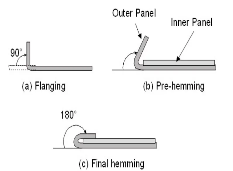
Hemming process:
Hemming is a forming operation in which the edges of the sheet are folded or folded over another part
in order to achieve a tight fit. Normally hemming operations are used to connect parts together, to
improve the appearance of a part and to reinforce part edges.
In car part production, hemming is used in assembly as a secondary operation after deep drawing,
trimming and flanging operations to join two sheet metal parts (outer and inner) together. Typical
parts for this type of assembly are hoods, doors, trunk lids and fenders.
The accuracy of the hemming operation is very important since it affects the appearance of the surface
and surface quality. Material deformations, which occur during the hemming process, can lead to
dimensional variations and other defects in parts. Typical hemming defects are splits or wrinkles in
the flange, material overlaps in the corner areas or material roll-in. Therefore it is important to use
simulation tools in order to, on the one hand, better understand the hemming process and, on the other
hand, significantly reduce the number of “trial and error” loops during tryout und production
There are various types of hemming operations:
Conventional die hemming is suitable for mass production. In die hemming, the flange is folded over
the entire length with a hemming tool. Normally the actual hemming is a result of a forming operation
in which the flange is formed with a hemming tool after the drawing and trimming operations have
been completed. The formed flange is then hemmed in several process steps. These steps include, for
example, the pre-hemming and final hemming depending on the respective opening angle of the
flange. Production plants for conventional die hemming are very expensive, but the cycle times are
very low
Roll hemming
Roll hemming is carried out incrementally with a hemming roller. An industrial robot guides
the hemming roller and forms the flange. Roll hemming operation can also be divided into
several pre-hemming and final hemming process steps. Roll hemming is very flexible to use
and tool costs are significantly lower as compared to those of conventional die hemming.
However, the cycle times are much higher since the hemming is realized using a hemming
roller which follows a defined path
Latch Trajectory and Striker Mounting:
In opening and closing the hood of a vehicle, the striker should be placed in such a manner that is
approximately same in all the vehicles. For that the striker should be mounted by measuring the
inclination angle and with respect to the hinge axis.
In the designing process, we shall make a hinge axis and the find out the center of the axis and then
draw a circle which is an approximate distance to fix the striker.
When the striker is in position, we will use the WAVE geometry linker to make the latch.
The Striker should be mounted in such a way that during the opening and closing of the hood, it
should be in place and there shouldn’t be any kind of vibrations or loosening. The components of a
latch are commonly formed from stamping. The stamped pieces are later assembled, and spot welded
into complete latches, although the process differs slightly for each type of latch.
Deep-Drawing:
Deep drawing is a sheet metal forming process in which a sheet metal blank is radially drawn into a
forming die by the mechanical action of a punch. It is thus a shape transformation process
with material retention. The process is considered "deep" drawing when the depth of the drawn part
exceeds its diameter. This is achieved by redrawing the part through a series of dies. The flange
region (sheet metal in the die shoulder area) experiences a radial drawing stress and a tangential
compressive stress due to the material retention property. These compressive stresses (hoop stresses)
result in flange wrinkles (wrinkles of the first order). Wrinkles can be prevented by using a blank
holder, the function of which is to facilitate controlled material flow into the die radius.
The total drawing load consists of the ideal forming load and an additional component to compensate
for friction in the contacting areas of the flange region and bending forces as well as unbending forces
at the die radius. The forming load is transferred from the punch radius through the drawn part wall
into the deformation region (sheet metal flange). In the drawn part wall, which is in contact with the
punch, the hoop strain is zero whereby the plane strain condition is reached. Mostly the strain
condition is only approximately plane. Due to tensile forces acting in the part wall, wall thinning is
prominent and results in an uneven part wall thickness, such that the part wall thickness is lowest at
the point where the part wall loses contact with the punch, i.e., at the punch radius. The thinnest part
thickness determines the maximum stress that can be transferred to the deformation zone. Due
to material volume constancy, the flange thickens and results in blank holder contact at the outer
boundary rather than on the entire surface. The maximum stress that can be safely transferred from the
punch to the blank sets a limit on the maximum blank size (initial blank diameter in the case of
rotationally symmetrical blanks). An indicator of material formability is the limiting drawing ratio
(LDR), defined as the ratio of the maximum blank diameter that can be safely drawn into a cup
without flange to the punch diameter. Determination of the LDR for complex components is difficult
and hence the part is inspected for critical areas for which an approximation is possible. During severe
deep drawing the material work hardens, and it may be necessary to anneal the parts in controlled
atmosphere ovens to restore the original elasticity of the material.
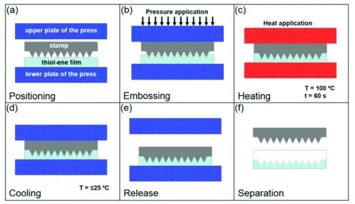
Embossing
Embossing is a stamping process for producing raised or sunken designs or relief in sheet metal. This
process can be made by means of matched male and female roller dies, or by passing sheet or a stripof metal between rolls of the desired pattern, theoretically with no change in metal thickness, or by
passing sheet or a strip of metal between rolls of the desired pattern. Metal sheet is drawn through the
male and female roller dies producing a pattern or design on the metal sheet. Depending on the roller
dies used, different patterns can be produced on the metal sheet.
CONCLUSION
The design of Hood Outer Panel and Inner Panel and the necessary reinforcements by following the
Master Section mentioned with the design parameters have been completed. All of the design was
carried out in the student version of NX CAD software