Hood design-Week 2
Hood design (BIW) -using Siemens NX
OBJECTIVE
The main objective of this project is to learn the Basics of the BIW (Body in white) through designing the Hood “also referred as Bonnet” of a car by considering all the Protocols and Standards of BIW Design.
INTRODUCTION
What is BIW?
Body in white (BIW) is the stage in automobile manufacturing in which a car body's frame has been joined together, that is before painting and before the motor, chassis sub-assemblies, or trim (glass, door locks/handles, seats, upholstery, electronics, etc.) have been integrated into the structure. Assembly involves different techniques such as welding (spot, MIG/MAG), riveting, clinching, bonding and laser brazing. Body in white refers to the stage in automotive manufacturing when a car’s sheet metal components are welded together which include:
.Hood
.Trunk lid
.Roof
.Front and rear fender
.Side wall
The term BIW derives from manufacturing practices before steel unibody monocoques — when automobile bodies were made by outside firms on a separate chassis with an engine, suspension, and fenders attached .The manufacturers built or purchased wooden bodies (with thin, non-structural metal sheets on the outside) to bolt onto the frame. The bodies were painted white prior to the final colour.
A folk etymology for "body in white" is the appearance of a car body after it is dipped into a white bath of primer (undercoat paint)— despite the primer's actual grey in colour. BIW could also refer to when car bodywork would be made of timber - all timber products, furniture, etc., are considered to be "in the white" when at the stage of raw timber before finishing or varnishing.
In car design, the "body in white" phase is where the final contours of the car body are worked out, in preparation for the ordering of the expensive production stamping die. Extensive computer simulations of crash-worthiness, manufacturability, and automotive aerodynamics are required before a clay model from the design studio can be converted into a body in white ready for production
What is a Hood?
A car Hood, also referred to as a Bonnet, is the hinged cover that rests over the engine of a front-engine vehicle. Its purpose is to provide access to the engine for repair and maintenance. A concealed latch is typically used to hold down the hood. On vehicles with an aftermarket hood and on race cars, hood pins may be used to hold down the car hood. Hoods sometimes also contain a hood scoop, wiper jets, power bulge, and/or hood ornament. Car hoods are typically constructed from steel and sometimes from aluminium. Aftermarket car hoods may be constructed from various other materials, including carbon fibre, fiberglass, or dry carbon. The hood design may vary from one make and model to another
Concerns regarding the severity of a potential pedestrian head injury during a collision with a motor vehicle have led to advanced hood designs on many models. Such designs may include a multi-cone inner hood panel design. An active structure that is capable of pushing the surface of the hood away from the vehicle's hard motor components in the event of a pedestrian crash is also in use. Pyrotechnic or spring force designs are often used in active-hood design
We can say a car hood is meant to protect the performance parts of your vehicle, including the engine, while also providing easy access for repairs and maintenance. It is possible for the hood to incur damage as well. One of the most common types of damage is to the hinge, which is the device that connects the hood to the body of the vehicle. Over time, the hinge can become loose or may fall off completely. The hood is also prone to receiving scratches and dents. Although this might appear to be a minor problem, dents and scratches can lead to depreciation in the value of your vehicle. Scratches and dents can also lead to exposure to the elements that can result in rust and corrosion. This can be a serious problem that can ultimately expose the engine in our car to snow, sunlight, and rain. When this happens, it can impact the performance of our car's engine.
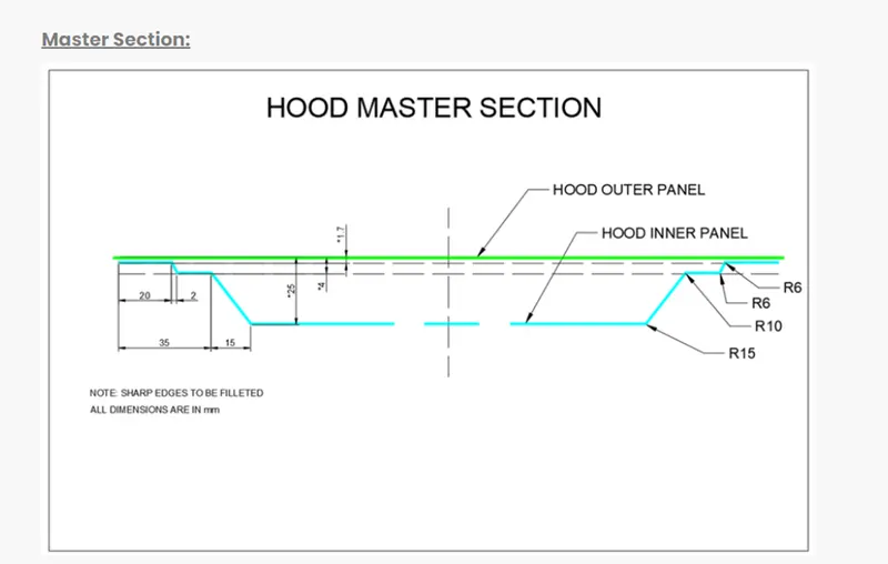
Master Section
DESCRIPTION
In this project we are going to create the Assembly of a Hood using previously given styling surface (outer panel surface) as the reference. The software used here to model the Hood is Siemens NX
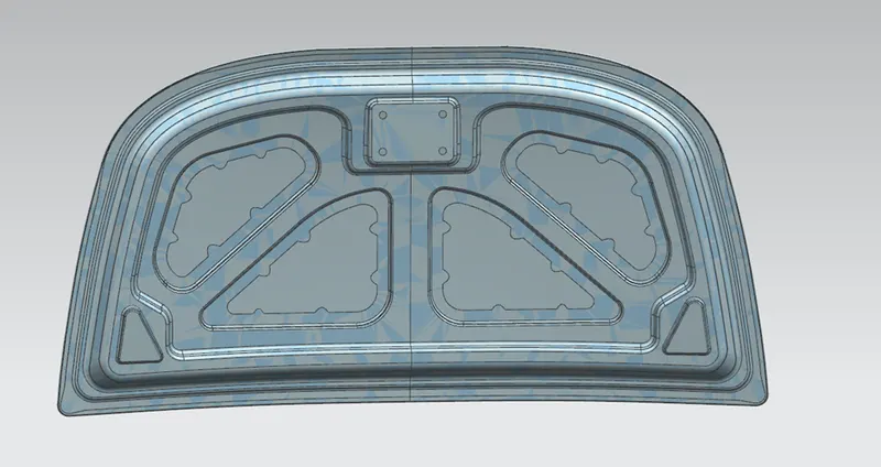
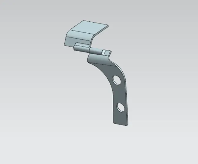
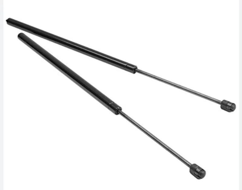
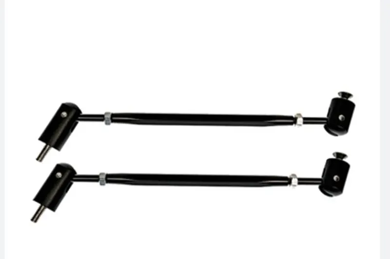
The assembly of Hood consist of various components such as Outer panel, Inner panel, Hinges, Supporting rod/gas stay and Striker. Here we are mainly dealing with, the design of inner panel which has a vital role in pedestrian safety, Stiffness and the strength of the Hood.
Outer panel
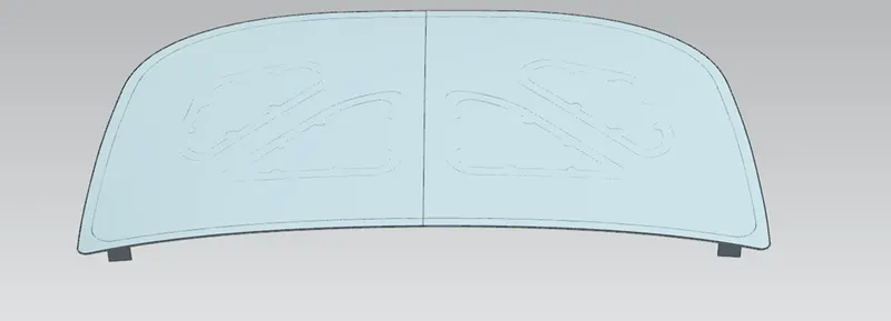
Inner panel
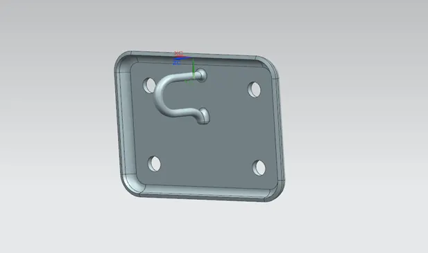
Striker
Hinge
Supporting rod/ Gas stay
For creating a hood, there are several Factors, protocols and standards a Design engineer should consider .Some of them are below
]
Major Factors to Consider
Material selection
Stiffness, strength and weight of the part
Pedestrian safety
Hinge position
Striker position
Distance from the outer panel to mastic points
Drawability
Hemming parameters
Holes (to mount supporting rod and to drain the primer from the cavities)
Material selection
BIW is expected to possess a number of significant properties. It must have high tensile strength as well as high stiffness—bending, torsional, static, and dynamic. It must also provide good quality safety both to the car body and to its occupants against crashes of all kinds—front, rear, side, or even rollover, meeting the Federal Motor Vehicle Safety Standard No. 208 [44]. It should also be able to protect occupants from noise, vibration, and/or harshness (NVH) by absorbing or reducing these conditions. Also, it should be easy to weld and form, as well as be highly paintable and easy to design. It should provide a good surface finish that is smooth, and should also be corrosion resistant. Improvement of fuel economy also necessitates the use of lightweight materials in BIW, as it constitutes a significant share of car’s weight; in addition, given environmental concerns in recent times, it is also expected to be recyclable. Given such extensive requirements, only steel and aluminium have been used for making BIW; the former is preferred for its high strength and low cost, while the latter is preferred for its lower density that helps reduce car weight
|
Material |
Yield Strength (MPa) |
Ultimate Tensile Strength (MPa) |
Reference |
|
steel |
210-1250 |
340-1520 |
46 |
|
Aluminium |
90 |
195 |
47 |
|
CFRP |
250-585 |
48 |
Here we are assuming Stainless steel as the material for the Designing of Hood
- Stiffness, strength and weight of the part
As the hood is a protector and the door that provides access to the engine and its attachments, it should have enough strength and stiffness .Stiffness, strength and weight of the hood depends up on major two factors .The first is the material selection, which is discussed above and the second one is the Design of the part.
A Design engineer can easily increase and reduce the stiffness of the part through his or her designs. The methods of increasing stiffness and strength of the parts are adding Embosses in the models.
Embossing
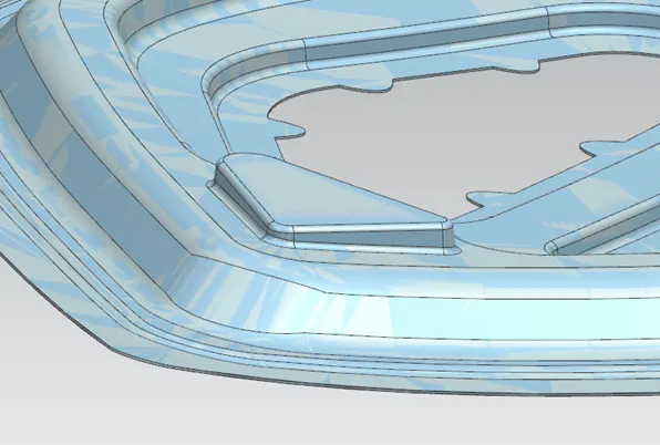
Sheet metal embossing is a stamping process for producing raised or sunken designs or relief in sheet metal. This process can be made by means of matched male and female roller dies, or by passing sheet or a strip of metal between rolls of the desired pattern .Adding of embosses to a sheet metal part , drastically increase the strength of the part.
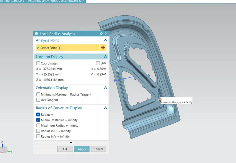
Here for the hood I have added several embosses with different length and angle as shown in the figure
- Pedestrian safety
A big percentage of all road fatalities in the Globe are pedestrians, with children and the elderly being at greatest risk. Pedestrians comprise one of the main categories of vulnerable road users, which also include cyclists and motorcyclists.
Most pedestrian accidents occur within city areas where speeds are moderate. The head, the lower body and the legs are amongst the most frequently injured body regions. To estimate the potential risk of head injury in the event of a vehicle striking an adult or a child, a series of impact tests is carried out at 40 km/h using an adult or child head form impact or. Impact sites are then assessed and the protection offered is rated as good, adequate, marginal, weak or poor.
EURO NCAP

Euro NCAP is a voluntary vehicle safety rating system created by the Swedish Road Administration, the International Consumer Research & Testing, backed by members, and motoring & consumer organizations in several EU countries. Euro NCAP has created the five-star safety rating system to help consumers, their families and businesses compare vehicles more easily and to help them identify the safest choice for their needs.
The number of stars reflects how well the car performs in Euro NCAP tests, but it is also influenced by what safety equipment the vehicle manufacturer is offering in each market. So a high number of stars show not only that the test result was good, but also that safety equipment on the tested model is readily available to all consumers in Europe. The star rating goes beyond the legal requirements and not all new vehicles need to undergo Euro NCAP tests. A car that just meets the minimum legal demands would not be eligible for any stars. This also means that a car which is rated poorly is not necessarily unsafe, but it is not as safe as its competitors that were rated better.
The safety rating is determined from a series of vehicle tests, designed and carried out by Euro NCAP. These tests represent, in a simplified way, important real-life accident scenarios that could result in injured or killed car occupants or other road users.
While a safety rating can never fully capture the complexity of the real world, the vehicle improvements and the technology brought the past years about by the application of high safety standards have been shown to deliver a true benefit to consumers in Europe and to society as a whole.
Many pedestrian crashes involve a forward moving car (as opposed to buses and other vehicles with a vertical hood/bonnet). In such a crash, a standing or walking pedestrian is struck and accelerated to the speed of the car and then continues forward as the car brakes to a halt. The pedestrian is impacted twice, first by the car and then by the ground, but most of the fatal injuries occur due to interaction with the car. Vehicle designers usually focus on understanding the car-pedestrian interaction, which is characterized by the following sequence of events: the vehicle bumper first contacts the lower limbs of the pedestrian, the leading edge of the hood hits the upper thigh or pelvis, and the head and upper torso are struck by the top surface of the hood and/or windshield.
WAD
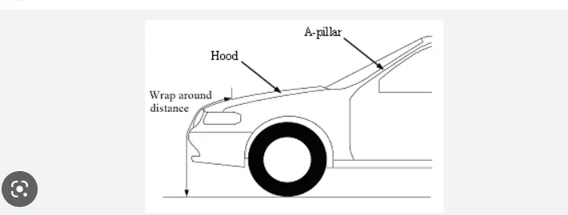
When a car crashes on the pedestrian, the whole human body wraps around the front shape of the car and the head impacts on the bonnet or the windscreen. The distance on which the head impacts on the car from the ground is called as the Wrap around Distance (WAD).
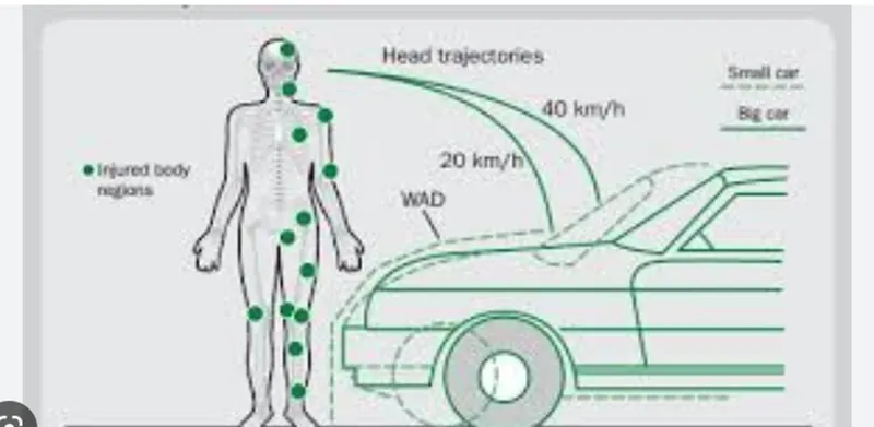
To be specific the Wrap around Distance is a measurement of distance from the ground to the head impact zone over the outer surface of the car. The wrap around distance is measured longitudinally in the centre of the vehicle from the ground. The severity of the injury caused by the frontal crash depends on the type and shape of the vehicle, speed of the vehicle and the movement of the pedestrian relative to the vehicle. In addition to these parameters, the wrap around distance plays a major role in the safety measurement of a pedestrian. During the crash analysis, based on the Wrap around Distance (WAD), two test areas will be created namely Child head impact zone and the Adult head impact zone. The child head impact zone is between 1000 to 1700 mm WAD and the adult head impact zone ranges between 1700 to 2100 mm WAD.
As we need to increase the NCAP rating, we should have to consider few things in designing. For increasing the pedestrian safety we can decrease the strength of the hood part where the head impact happens .By Taking WAD distance from the ground we are able to find the normal head impact area for adults as well as children.
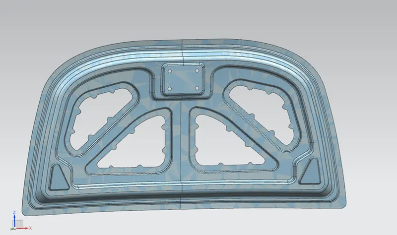
Here I have done some large cut outs in the inner panel of the hood where head impact happens, without compromising in the stiffness and strength of the part .The Large cut out also help me to reduce the weight of the part
4.Hinge position
Hinges are the part which helps to open the hood from the engine compartment for any repair or to clean it. One part of the hinge is connected to the inner panel of the hood while the other is connected with the engine compartment.
There are a few things to consider while the positioning of hinges in the hood.
The surface where the hinges to be mounted must be flat in order to keep the hinge tightly in touch with the inner panel , otherwise it leads to loosening of the fasteners resulting in NVH ( Noise ,Vibration and Harshness)
Reinforcements must be provided on both hinges .Because in sheet metals adding another solid body or a sheet body on it, will results in decreasing the strength of the part. To overcome this problem Reinforcements are used
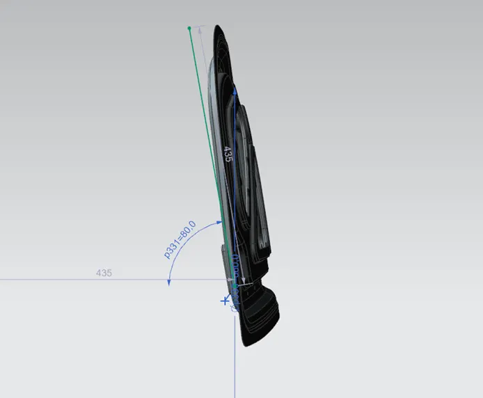
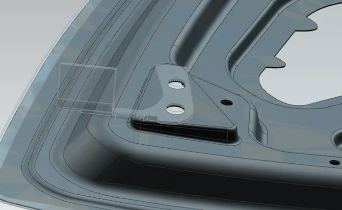
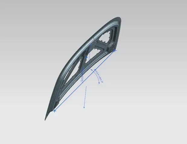
The central line or the axis of each hinges must be collinear
I have created an emboss with a flat surface which is created using a new datum plane as the End cap and I have attached the hinge along with the reinforcements. The central axis of both the hinges is collinear.
5.Striker position
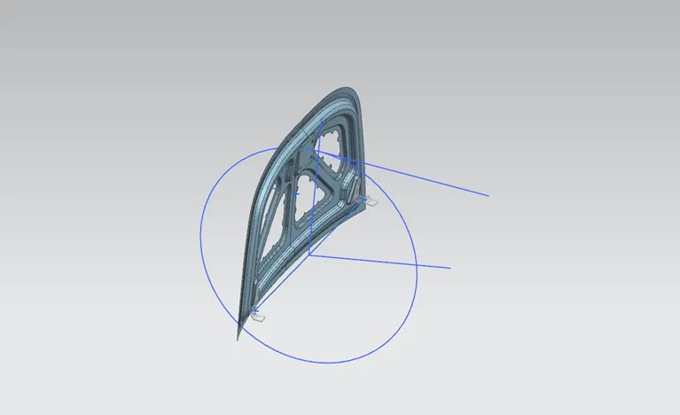
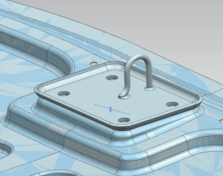
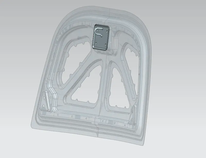
Placing striker on the hood is one of the major factors to take care of .As a striker is separate body and itself reinforcement, there is no need to add extra reinforcements. But like in hinges it’s compulsory to have a flat surface to mount on it. The striker in the hood and the Latch in the engine compartment must be normal to a trajectory path to have a smooth locking and unlocking.
To achieve this I have drawn a circle from the central axis of the hinge and a tangent line in the inner panel and another perpendicular line in the striker as shown in the figure .I have made the two lines constrained with touch. Then I have created an emboss using an extracted face (flat surface) from the striker to the inner panel.
6.Distance from the outer panel to mastic points
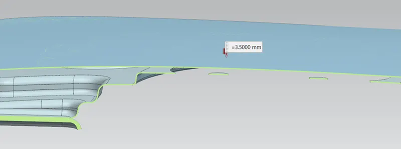
The Mastic sealant or the Mastic point is an elastic compound that behaves like a rubber. The mastic points are defined on the hood inner panel where the hood can easily deform. They help the hood outer panel to come back to its original shape after it gets deformed .The distance from mastic points to the outer panel must be 2-8 mm . Here I have given a distance of 3.5 mm from the outer panel to the mastic points in the inner panel
7.Hemming parameters
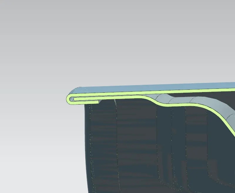
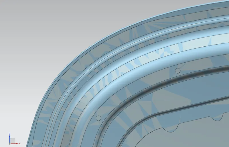
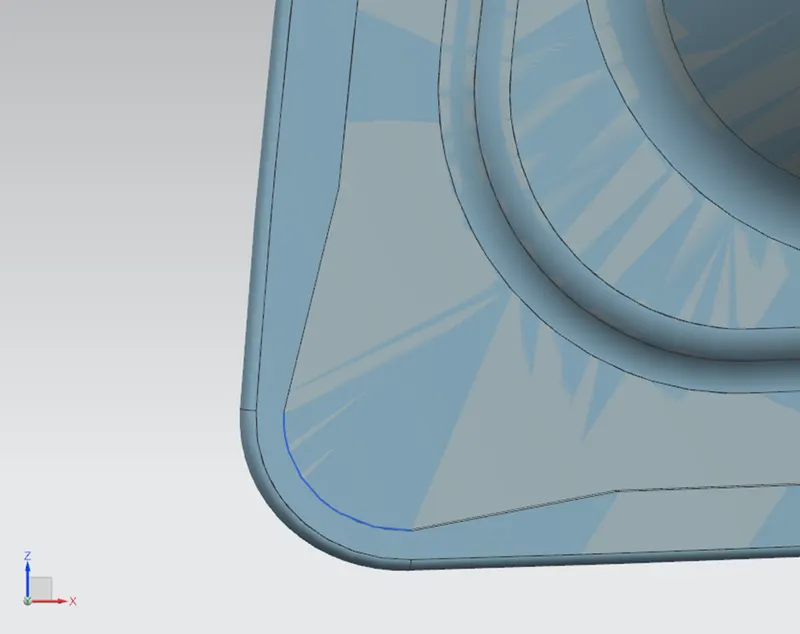
Hemming is a sheet metal forming process in which sheets are joined by bending it usually to 180°. Automotive body panels and automotive parts such as deck-lids, trunk-lids, doors, hoods and tailgates are formed by hemming process. While hemming the gap between two sheet metals must be in between .2 to .5 mm and the distance bend of the outer sheet metal to the edge of the inner sheet metal must be 2 mm. Corner reliefs should be applied in the corners in order to attain a smooth hem without wrinkles
Here I have followed these two criteria as well. And the section of my model is depicted below
.Corner reliefs
8.Drawability (Draft Analysis)
To understand what drawability is, first we should know what deep drawing is
Deep drawing
Deep drawing is a sheet metal forming process in which a sheet metal blank is radially drawn into a forming die by the mechanical action of a punch. It is thus a shape transformation process with material retention. The process is considered "deep" drawing when the depth of the drawn part exceeds its diameter. This is achieved by redrawing the part through a series of dies. The flange region (sheet metal in the die shoulder area) experiences a radial drawing stress and a tangential compressive stress due to the material retention property. These compressive stresses (hoop stresses) result in flange wrinkles (wrinkles of the first order). Wrinkles can be prevented by using a blank holder, the function of which is to facilitate controlled material flow into the die radius. The feasibility of this deep drawing is called DrawabilitySo While designing we must also consider the feasibility of deep drawing; otherwise the model will not be able to manufacture. Draft analysis in Siemen NX is one of the tool used to study the deep drawing feasibility easily through checking draft angle in the various faces .The Designer should Define a tooling direction in-order to check the draft angles
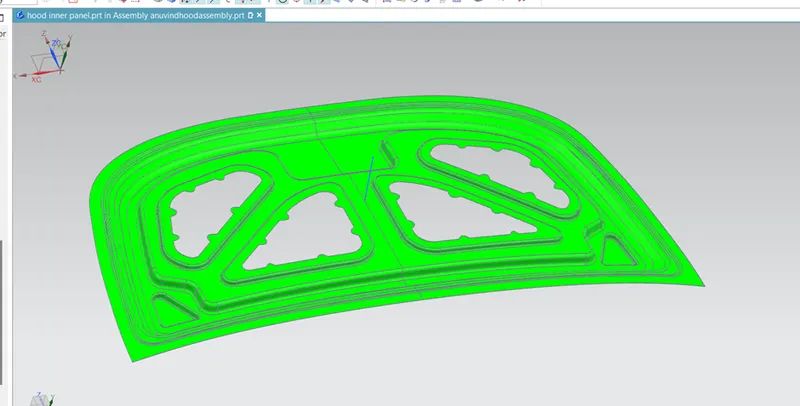
For my design (inner panel), I have done draft analysis by defining a tool direction which is perpendicular to the plane created using the corner points of the model. Here the line is my tooling direction and i have kept the limit angle to 7 degree. In this tooling direction i could find some areas with yellow colour .There are four colours appear in the draft analysis which is red, blue, green, yellow .Each colour shows the limit angles. “Red - <-7, Blue - =7 to -7, Yellow - 0 to 7, Green - >7 ".So i have tried to increase the limit angle in the yellow areas by changing the tool direction. I have drawn a new line for the tooling direction which has a 5 degree angle against the previous perpendicular line. The result is given Still i could find some yellow regions when i have zoomed the model. To overcome this issue i have decided to increase blend radius and i have succeed in obtaining the part colour completely to green.
9.Holes
(To mount supporting rod and to drain the primer from the cavities)
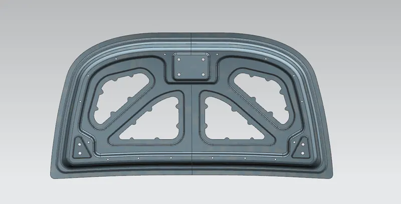
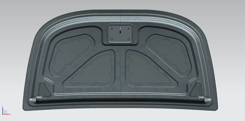
In the inner side of the hood we can see several holes on it. Every hole in it has its purposes. We know One hole will be for mounting the supporting rod while opening the hood .Then why the others? Because these holes allow e-coating, surface prep, and primer to drain from the cavities in between the hood skin and hood skeleton after the chassis is dipped into these during production can find the holes that I have provided in my hood design in the picture shown
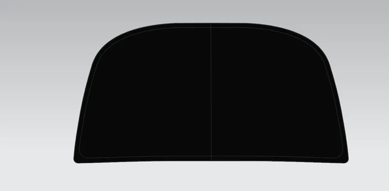
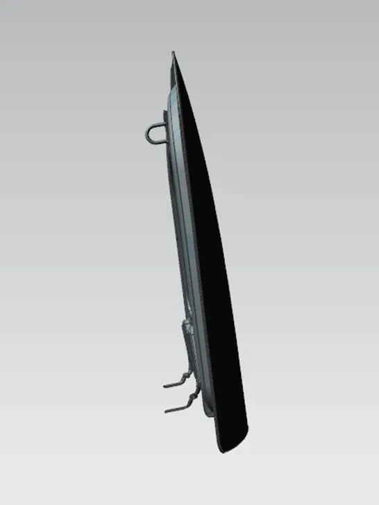
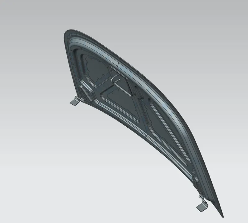
FINAL IMAGES OF ASSEMBLY
CONCLUSION
Designing of hood have been completed successfully by considering all major standards and protocols of BIW design