Advanced Sheet Metal Design Using NX Cad Challenge_2_Box Assembly
SHEET METAL BOX ASSEMBLY DESIGNING USING SIEMENS NX
OBJECTIVE
To create a sheet metal Box assembly design using Siemens NX cad software for improving Sheet metal designing skill
INTRODUCTION
Sheet metal is one of the most versatile materials in the manufacturing industry .Its made from steel, aluminum, brass, copper tin, nickel, titanium or precious metals .It ranges in thickness from wispy leaf through light foil to heavy plates. It takes a variety of forms. plain flat sheets ,embossed .etched ,ribbed ,corrugated and perforated .And its uses expand across many different industries including transportation aerospace ,appliance manufacturing consumer electronics , industrial furniture machinery and more
Sheet metal components can have deceptively complex manufacturing processes and the design process itself can be similarly tricky .CAD software’s such as Siemens NX cad, SOLID WORKS etc. are used to design the complex Sheet Metal components
Sheet metal design software
Considers the fabrication methods needed for manufacturing. As we create flanges add bends, the sheet metal designs software will accurately represent the flat pattern required. The flat pattern can be used to document and manufacture associatively the design changes
Here in this project we are dealing with Sheet metal Box assembly designing using the software Siemens NX
DESIGN METHODOLOGY
Here the metal box is created in a single part document as different bodies .The box consist of different bodies like the box the lid and the hinges .This box design consists of Repeated features like cut-out ,bends ,flanges ,holes dimples and beads . Every feature is designed in an order following the industrial procedure to keep the design intent. The design methodology used for this project can be summarized as depicted in the flow chart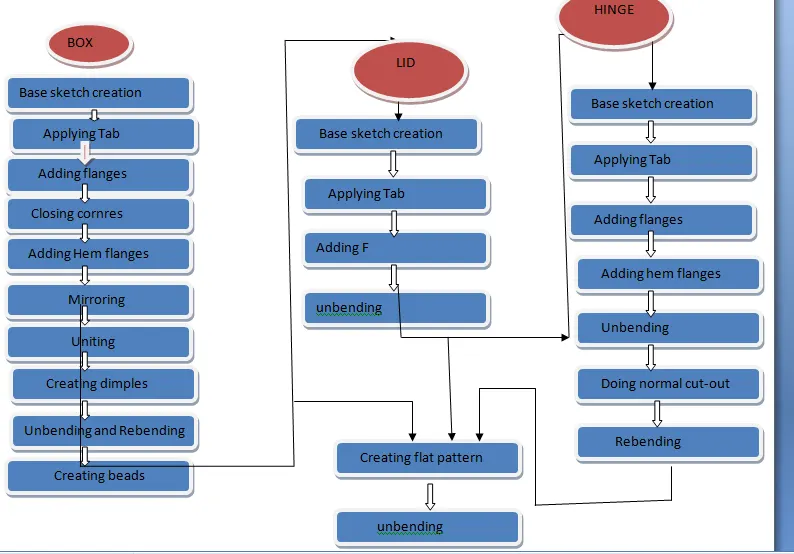
COMMANDS USED
SKETCH
TAB
FLANGE
HEM FLANGE
BREAK CORNER
CLOSED CORNER
UNBEND
NORMAL CUT OUT
DIMPLE
BEAD
REBEND
MIRROR BODY
UNITE
FLAT PATTERN
DRAFT
SKETCH
Sketches are the basic; we can say the foundation of a design model. A base sketch is needed to perform most of the operations in a sheet metal designing including Tab, Dimple, Bead, Hole, Contour Flange etc. The sketches can be created using various sketch tools provided top left corner of the interface
TAB
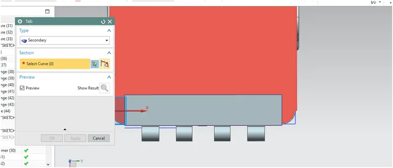
Normally tabs are the features in NX sheet metal designing process .Tab command extrude a sketch along a vector by a thickness value or by adding material to existing face and bend regions of sheet metal part
FLANGE
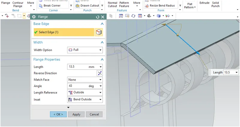
A flange feature consists of a face and bend connected to an existing face along a straight edge. To add a flange feature, we select one or more edges and specify the size and position of the material added
HEM FLANGE
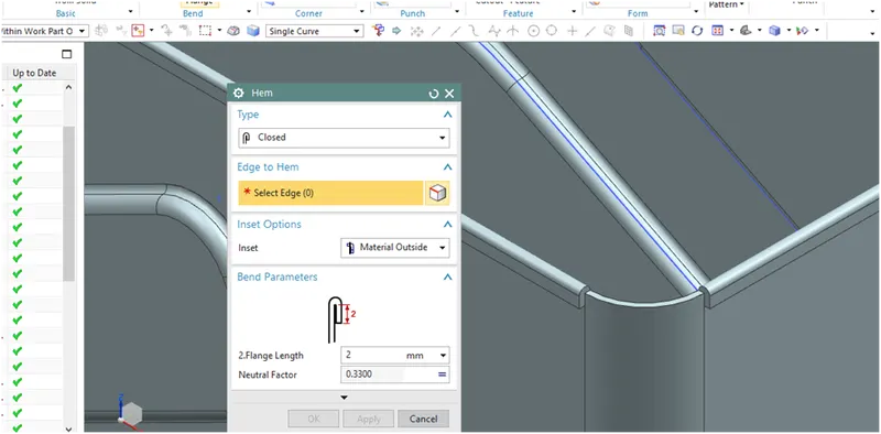
Hemming is sheet metal forming operation in which the edge of the sheet is folded back on itself .It serves several purposes to fasten two sheet metal parts, to improve appearance of edges (remove burrs and rough edges )and to increase the part stiffness
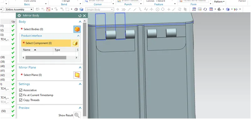
MIRROR BODY
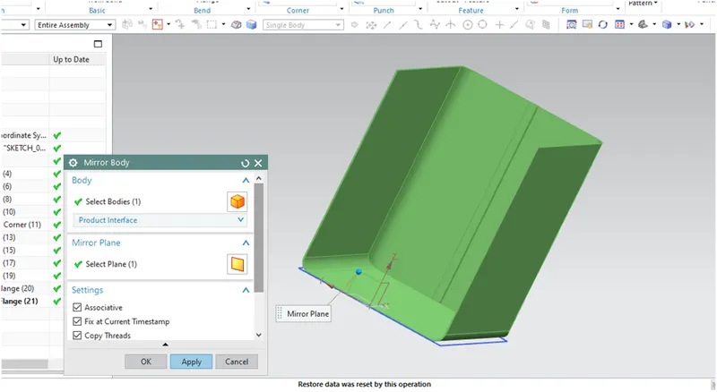
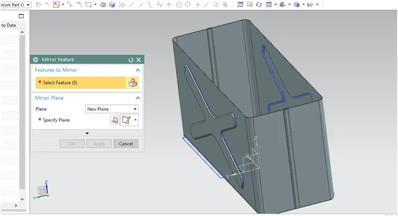
Mirror body feature allows the solid body to get copied and mirrored with respect to a plane. Here, the design made till this stage is a half part of the box which is then mirrored with respect to YZ plane .A black edge appears on the face of the side flange representing the separation between two bodies
UNITE
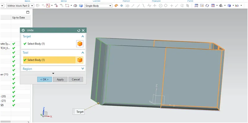
After mirror of the body is completed it results in two separate bodies which is not the intended one. Unite allows us to combine the bodies and make one single body. After applying the unite feature the black edge on the face disappears
BREAK THE CORNER
The command used to break or round the corners in a solid body in order to avoid accidents by the sharp edges
CLOSED CORNER
The command use to close the corners in between two flanges or bends is the closed corner feature
UNBEND
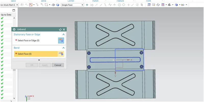
Use the unbend tool to unbend one or more curved surface such as bends or curved walls to a flat configuration in a sheet metal part . For performing a unbend feature its must to define a fixed planar face or edge . We can either select bend geometry individually or automatically select all the bend geometry
NORMAL CUTOUT
Normal cutout command extract volumes from sheet metal by using sheet metal production principles .Cutting faces will be perpendicular to the sheet metal surface
DIMPLE
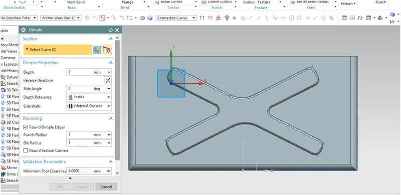
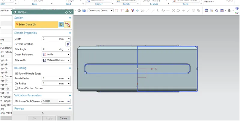
Use this command to create a raised dimple feature in sheet metal part. The dimples can be placed on any flat surface including flanges and will extend in the options form. Dimple also helps the sheet metal part to increase its stiffness
BEAD
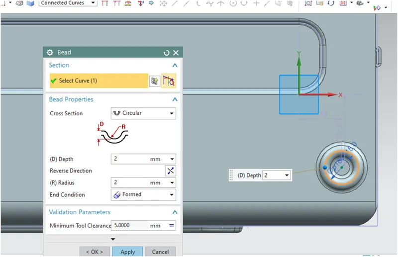
Beads are the features added in sheet metal components in order to increase the stiffness of the components. Beads require a sketch in order to apply the feature.
It can be either an open or closed profile. For this casing design project, four small beads are applied in the symmetric positions as shown in the image below.
REBEND
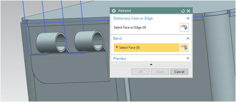
To rebend the untended parts along with the feature applied after the unbend. After addition sketches and features the sheet metal is to be re bended to its required shape .This operation is done by box selecting all the features and clicking the Rebend command
FLAT PATTERN
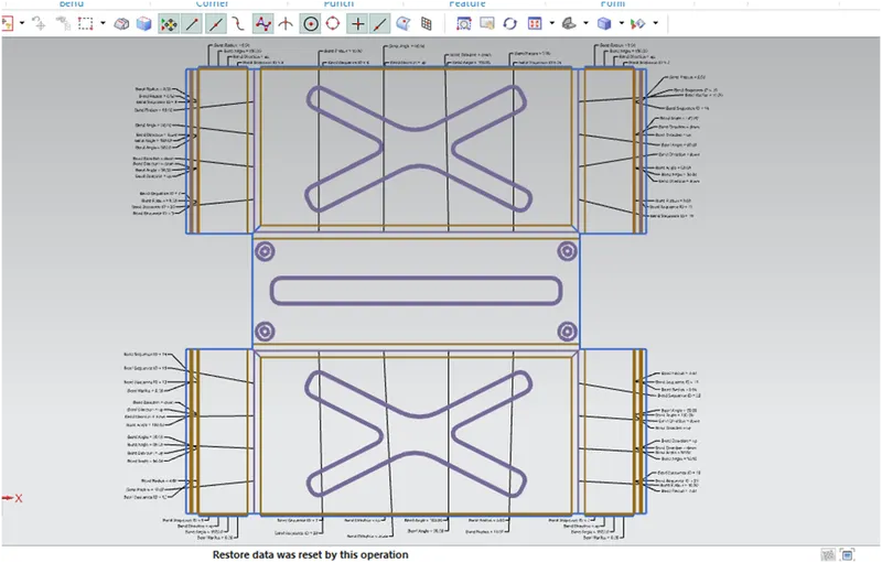
Flat pattern is the representation of the entire metal component in the 2D form with all the bends, cut- outs, holes and additional features in the form of lines or edges. The flat pattern ensures the ability to cut the sheet metal out of the raw sheet metal plate. It removes the possible errors such as interference or collision within the same component
DRAFT
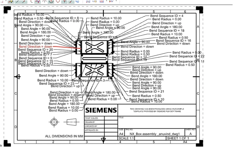
After the modeling, the manufacturing of the component a technical 2D drawing of the component with accurate dimensions or scales denoted. For achieving this we are using the command Draft
PROCEDURE
The Box assembly is created as different bodies such as
BOX
LID
HINGE1
HINGE2
BOX
Created a Base Sketch and perform the Tab feature with 1 mm thickness
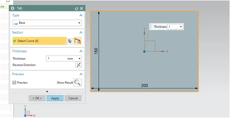
Create Flanges from the two edges with 200 mm length and 10 mm bend radius as given in the picture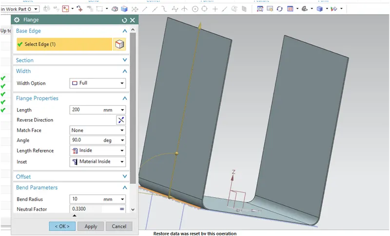
Create another two Flanges from the edge of the previously created flanges with 70 mm length and same 10 mm radius
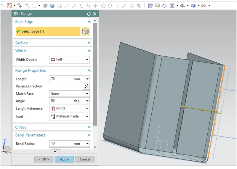
Close two corners using the closed corner set the type to corner and relief
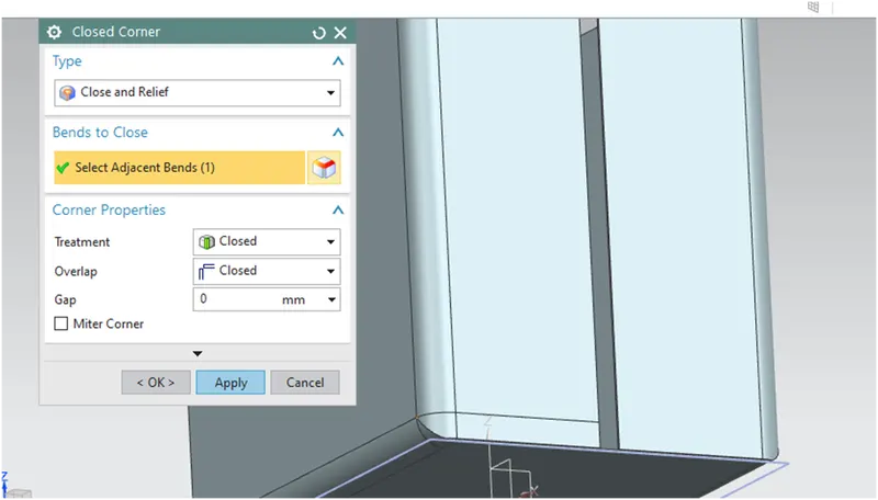
Create 2 flanges one over the other on the edge shown in picture .Apply specified length and bend radius
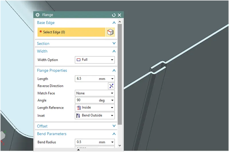
Do the same operation on the opposite edge
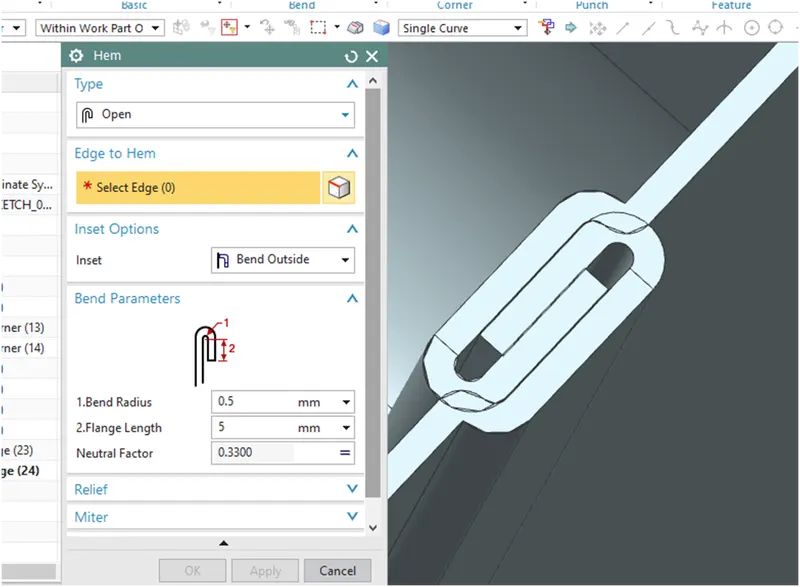
Create two hem flanges on the edges of the previously created Flanges with 5mm length and 0.5 degree bend radius. Set the flange type open
Mirror the body about the YZ plane and ensure all the option in the feature menu is ticked
Unite the mirrored parts in to one
Using the proper sketch create Dimple with 1 m depth on the side face of the box
Mirror it to the opposite side
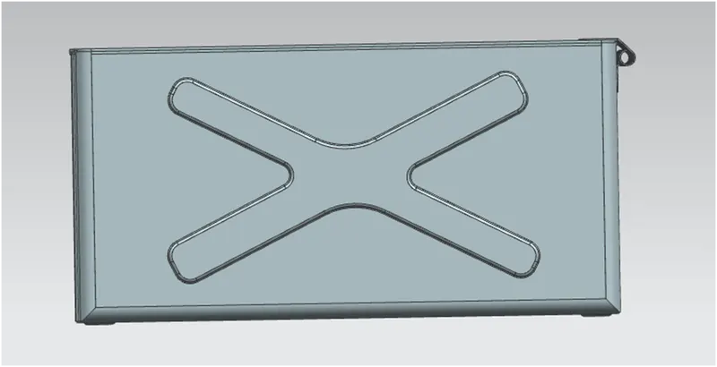
Create another Dimple on the bottom side with 1mm depth using a slot sketch od 350mm length ,30mm width ,10mm radius
Using a 15mm radius circle create a Bead on one bottom corner and mirror it to all the other three corners
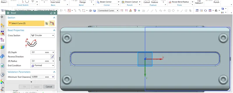
Unbend and Rebend the body
Apply Hem flanges on the top outer edges of the box as shown in the figure with 2mm length
Lid
Create a Datum plane with 203 mm away from the origin, linear to XY plane
Create a sketch lid by converting the upper edges of the box and Create A Tab with 2mm thickness
Create Two flanges on the two edges of the lid with a length of 3mm
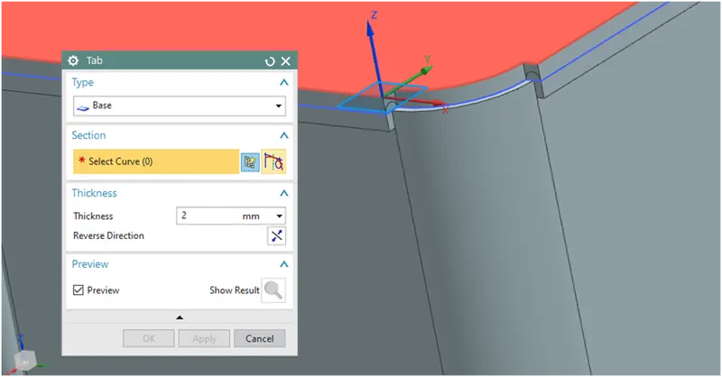
Hinge 1
Create a Tab using a rectangle sketch of 55mm length and 20mm width on the right side face of the box
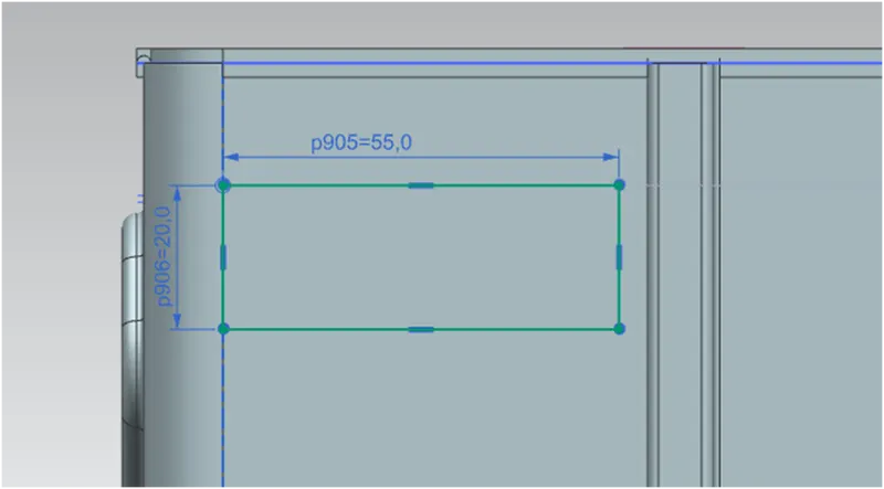
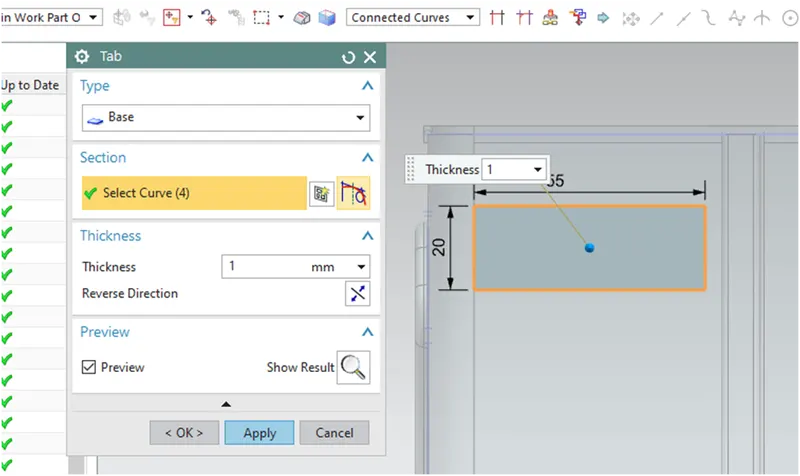
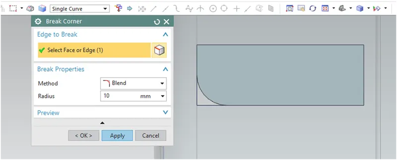
Break the corner with 10mm radius using Break corner command
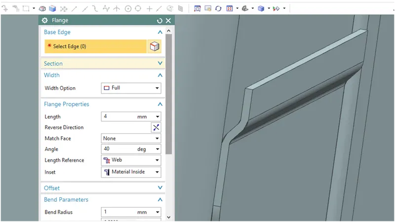
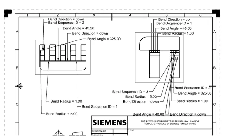
Create 2 flanges with 4mm length and an angle of 40 degree as shown in the figure
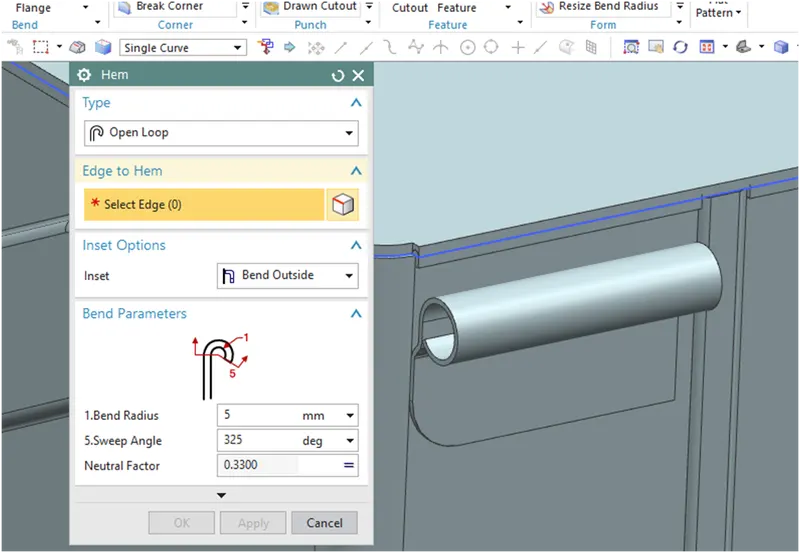
Create a open loop type hem flange on the edge of the newly created flange with a sweep angle 325 degree and bend radius 5 degree
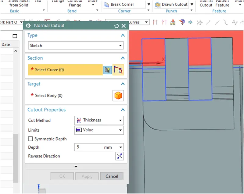
Unbend the body and perform a normal cutout with the given sketch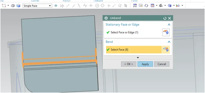
Rebend the body and mirror the body to opposite side
Hinge 2
Create a new Tab on the top surface of the lid using a rectangle sketch as shown in figure
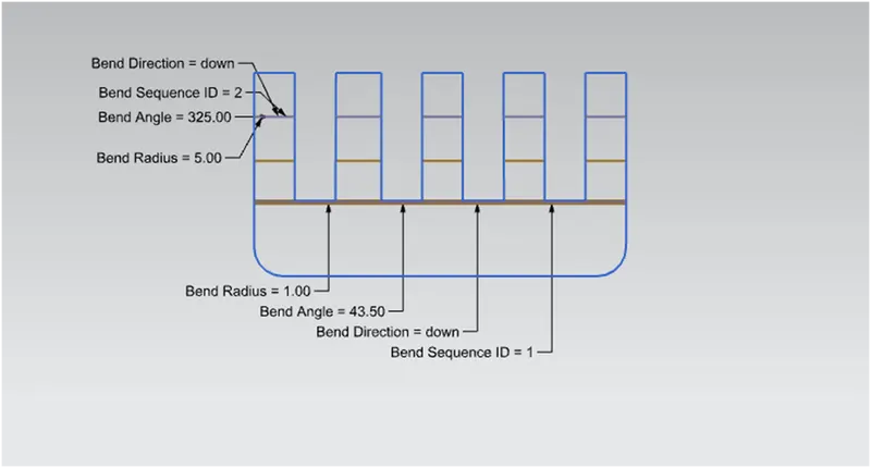
A Flange of 5mm length and 43.5 degree angle is created on the edge of the newly created tab as in the picture
Create a open loop type Hem flange of 325 degree sweep angle and 55 mm bend radius
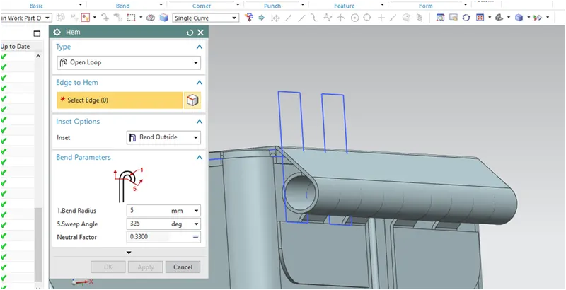
Unbend the Body and Do a Normal cutout using the proper sketch and rebend the body back to its required shape
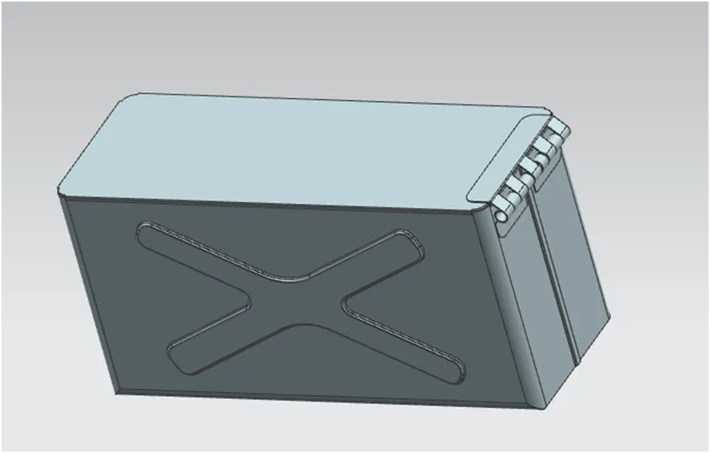
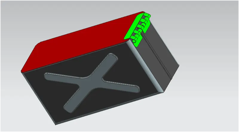
The modeling of box assembly is completed here. The different view are given below
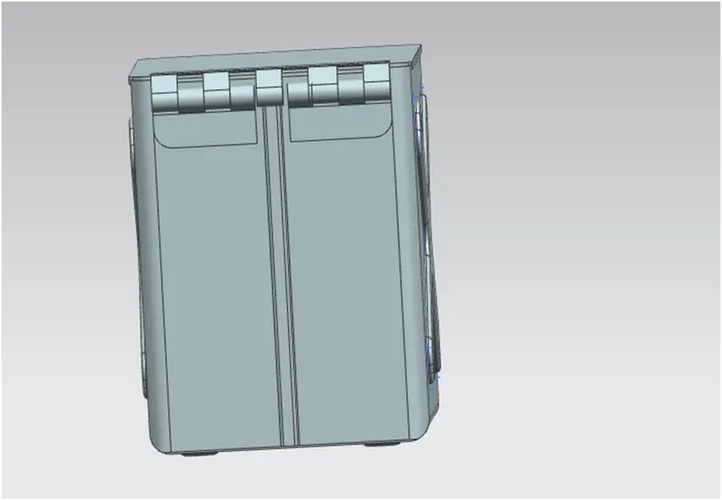
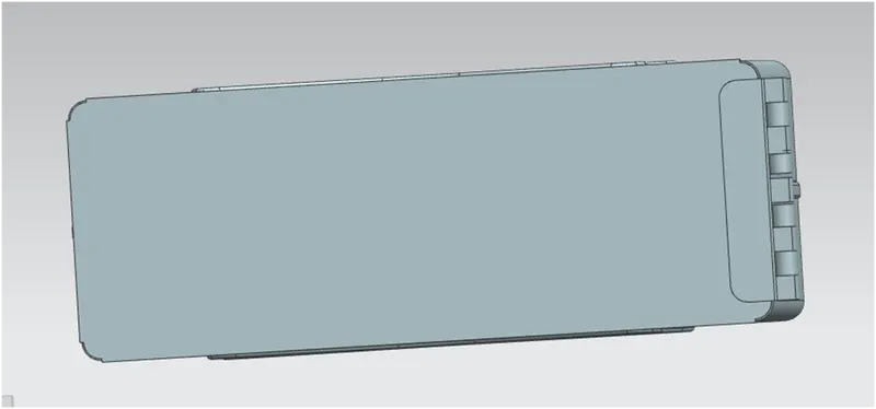
Apply suitable color to the model for a better look
Flat pattern of each bodies are below
1 box
Hinge 1
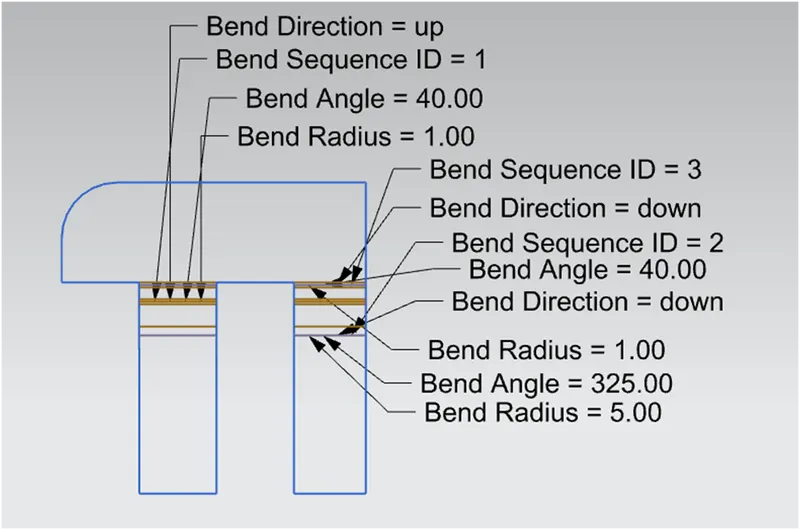
Hinge 2
Drafted images
Conclusion
The box assembly is designed perfectly with an awesome appearance