Hood design-Week 2
DESIGN A HOOD USING NX CAD
AIM
To Design a Hood that satisfies the manufacturing requirements, functional requirements as per Euro NCAP standards.The Body in white (BIW) Inner panel and Outer panel of the hood to be designed and assembled with the Hinge Assembly, Latch and Striker with their reinforcements.
HOOD DEFINITION
The Hood of a car is considered as the frontal BIW enclosure component. Bonnets are designed to reduce air resistance as the air flows around the car. The design of the Hood is vital since it affects the aerodynamic flow around the car. Apart from this, Hoods are also designed to meet several other requirements. They serve a great deal of purpose in protecting the passengers inside the car and the pedestrians in the event of an accident. It also acts as the engine cover. it is considered as the closure sheet-metal component.
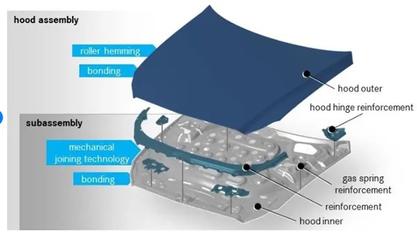
The hood consists of the following parts.
- Hood outer panel
- Hood inner panel
- Latch and Striker re-enforcement
- Hinge re-enforcement
- Gas stay re-enforcement
LATCH AND STRIKER RE-ENFORCEMENT
A striker reinforcement plate for support of a striker member on an automotive vehicle body. The plate has a first substantially planar face, including at least two holes for receiving mating bolts or screws. A flange extends from multiple edges of the face substantially perpendicular to the face. The flange includes mounting tabs extending outwardly and substantially perpendicular to the flange. The mounting tabs are provided for mating with an automotive vehicle pillar. The face of the striker reinforcement plate mates with a rear surface of a striker stiffener.
HINGE RE-ENFORCEMENT
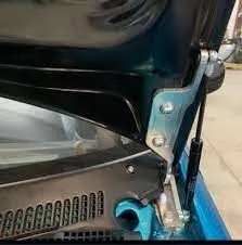
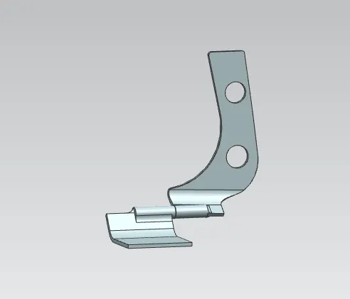
hood hinge reinforcement described in the utility model, has reinforcement body, it has hinge attachment point.It is characterized in that described reinforcement body is rectangular slab, the both sides up and down of reinforcement body are formed with reinforcement flange, flange has coating groove and scribbles expansion glue, are connected with front hood panel by expansion glue, hood panel before supporting, reinforcement bottom surface is welded with front hood back head.Structure described in the utility model has had more two flange and expansion glue that mate with outside plate compared with common hinge reinforcement, effectively can increase front hood hinge attachment point rigidity through CAE measuring and calculating.
GAS STAY RE-ENFORCEMENT
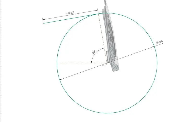
A gas stay is a spring that operates due to the force exerted by the compressed gas (usually Nitrogen) stored inside the cylinder. Luxury carmakers provide a gas strut to lift the hood and hold it in place. It takes minimal efforts to lift an otherwise heavy hood and lends that upmarket feel to the car.

WRAP AROUND DISTANCE (WAD):-
It is the distance measured from the ground to the head impact zone over the outer surface of car i.e.windshield area as the value ranging from 0mm to 2100mm. The value for child and the adult differs. It is calculated as when the pedestrian gets hitted by the car, their body wraps around the car bonnet and head impacts takes place which leads to injury so as to reduce the chance of high injury the bonnet is not made of high strength material and is made of a material which do not give a huge impact to pedestrian head.
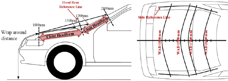
(1) Child head impact zone:- 1000mm - 1700mm
(2) Adult head impact zone:- 1700mm - 2100mm
Global NCAP crash-test cars
A front offset crash test is designed to simulate a head-on collision between two cars. In the Global NCAP test, the car is driven at 64kph and with 40 percent overlap into a deformable barrier which is the equivalent of a crash between two cars of the same weight, both moving at 50kph.
NCAP tests to get tougher from 2022
Even though an increasing number of Indian vehicles have done well in GNCAP’s crash tests recently, it must be remembered that the watchdog only assesses them for (passive) crash safety for now. However, this is set to change in the coming years, with greater consideration being given to (active) crash avoidance,The GNCAP testing will become tougher in next year 2022 will see ESC being introduced as a requirement for achieving higher ratings, and the side impact test is also set to become standard procedure. Come 2026, GNCAP will overhaul its testing protocol, giving a single star rating (instead of the current system of separate ratings for adult and child occupants) and including assessments for more active safety tech.
The basic requirement for designing hood is
Hood Thickness and manufacturing considerations.
- Outer Panel Thickness = 0.75mm
- Inner Panel Thickness = 0.75mm
- Reinforcement Thickness = 1.5mm
- Minimum fillet radius = 3mm+Thickness (example: When thickness of inner panel is 0.75mm we need to maintain minimum fillet radius 3+0.75=3.75mm)
- No sharp corners inside the component
- No curvatures lesser than 5mm
- Small embosses should not exceed the maximum depth of 6mm (staying on the safe side)
- Mounting areas and welding areas need to be flat
- Provide appropriate corner relief on the area of curvature
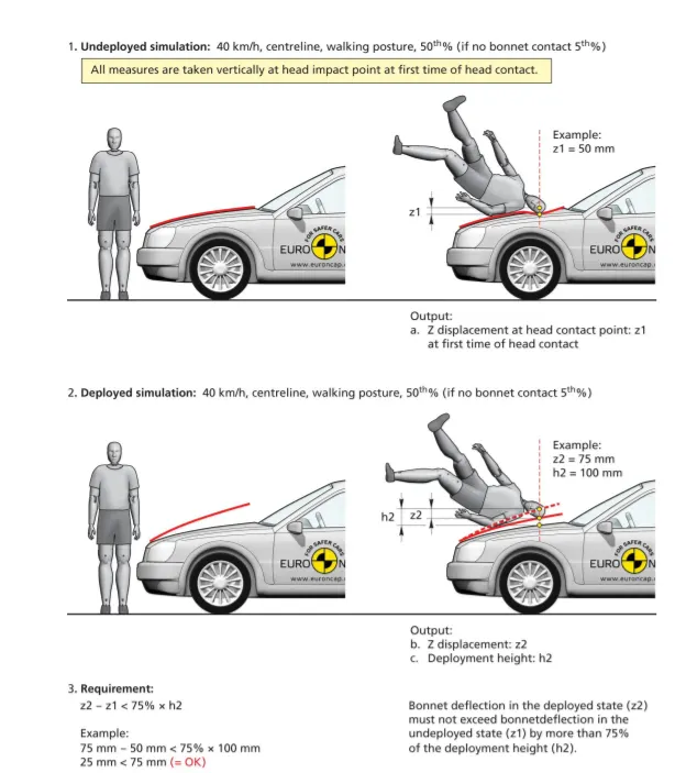
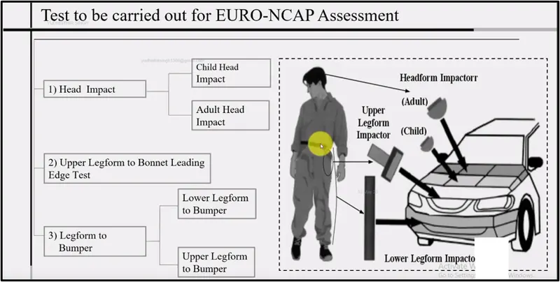
Pedestrian Safety Measures:
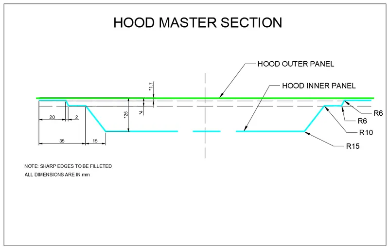
The master section to design a hood panel
The commands to be followed to design hood inner and outer panel,
OFFSET SURFACE
the Offset Surface command to create an offset of one or more existing faces. The result is a new body (or bodies) with an offset relation to the chosen faces. it creates a true offset surface by offsetting points along surface normals of the selected face.
1 Offset surface
2 Vector direction
3 Selected face
OFFSET CURVE ON SURFACE
The command to create offset curves on one or more faces from connected edges or curves on the surfaces.The curves are created on the face, and are measured along face sections normal to the original curves.
-
Different spanning methods let you fill the gaps between the curves. There are also options to let you trim against the selected face boundaries.
-
The resulting offset curves are either cubic splines or analytic curves, depending on the input curves and the faces from which they are offset.
-
The offset curves can be created outside, of off their faces if there is enough surface.
-
The Modeling Distance Tolerance parameter determines how accurately the offset curve approximates the true theoretical offset curve, although you can specify your own tolerance.
-
Use the same options to edit an Offset in Face feature that you used to create it.
|
TRIM SHEET
the Trimmed Sheet command to trim sheet bodies to intersecting faces and datums, and projected curves and edges.
The following example shows a sewn sheet body trimmed by two intersecting surfaces and one set of projected curves.
-
Sheet body to be trimmed.
-
Intersecting surfaces selected as boundary objects.
-
Curves selected as a boundary object.
-
Selected projection direction for selected boundary curves.
THROUGH CURVES
the Through Curve Mesh command to create a body through a mesh of sections in one direction, and guides in another direction, where the shape fits through the mesh of curves.
This command uses sets of primary curves and sets of cross curves to create a bi-cubic surface.
-
Each set of curves must be contiguous.
-
The sets of primary curves must be roughly parallel and the sets of cross curves must be roughly parallel.
- Control cross curve parameterization with a set of spine curves.
-
Locate the surface near the primary curves or cross curves, or at an average between the two sets.
LAW EXTENSION
the Law Extension command to extend an existing surface or sheet based on the laws for distance and the angle of the extension.
Law Extension creates flanges or extensions when a particular direction is important or when it is necessary to reference the existing face. For example, in die design or mold design, draft direction plays an important role in creating parting surfaces.
EMBOSS
the Emboss Sheet command to modify a sheet body by adding faces of a solid body, as if the solid body was pressed into the sheet body.
Sheet metal models are embossed to:
-
Increase a metal panels stiffness and rigidity.
-
Increase the surface area for heat transfer or acoustic applications.
-
Improve traction.
-
Enhance the ability of a metal surface to disperse fluids efficiently.
-
Reduce friction and static.
MASTIC DATA
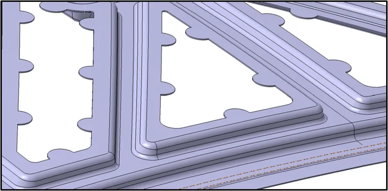
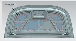
Mastic points were the gluing points where the paste is applied between the inner and outer panel to join the panels. Each mastic point will stiffness up to 80mm surrounding. So mastics to be added in such a way that it covers entire surface of the hood. If the gap is less than 5mm between the outer and the inner panel without mastic points it will cause vibration resulting in NVH problem. Below image shows the mastic points where the paste is applied, and it will get hardened in further processes resulting in a rigid joint.
EDGE BLEND
the Edge Blend command to round sharp edges between faces.
-
Add a single edge blend feature to multiple edges.
-
Create an edge blend of constant or variable radius.
-
Add corner setback points to change the shape of an edge blend corner.
-
Adjust the distances of the corner setback points from the corner vertex. You can use corner setbacks to create ball nose blends, for example, and as an aid in sheet metal stamping of non-styled surfaces.
-
Add stop short points to end an edge blend short of a specific point.
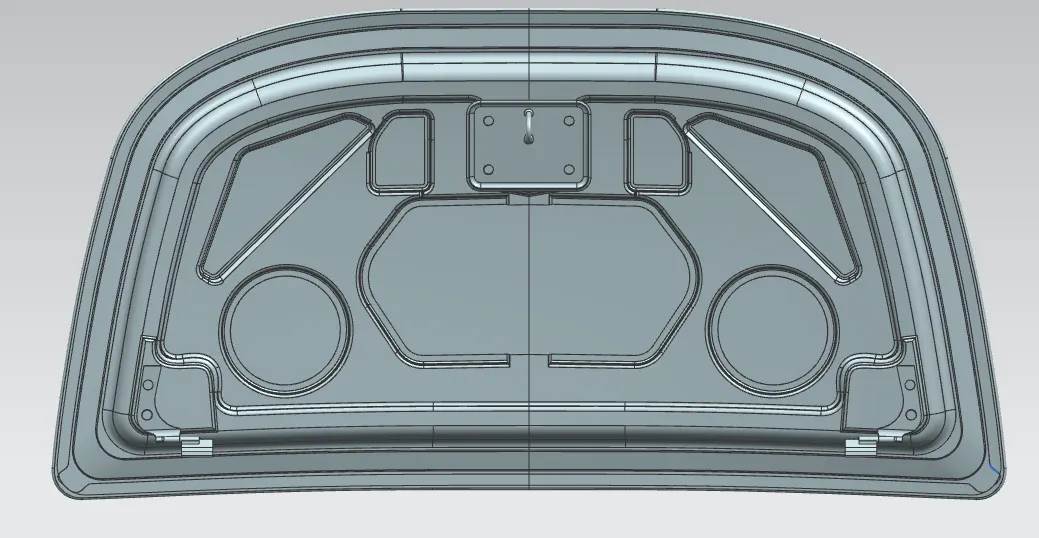
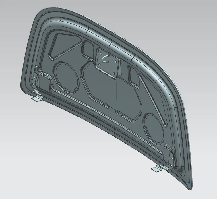
The final assembly of inner and outer hood panel
CONCLUSION
The inner and outer hood panel design is done using nx cad