Hood Assembly Design
Introduction:
The car hood is the component which covers the engine and mounted in the engine compartment on front-engine cars. Hood provides access to the engine by opening in the vertical direction. The style and design of opening the hood has changed over time from splitting in two sections to hinged at rear end of engine compartment.
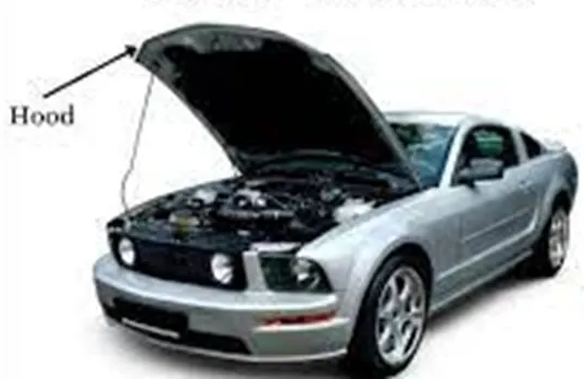
The hood protects the engine and other connected components from outside debris as well as provide aerodynamics to the car.
The material used for production of the hood varies according to the needs of the car. Usually, steel and aluminium are used on normal cars but for performance vehicles fiberglass and carbon fiber hoods can also be implemented.
Methods of manufacturing:
This hood is manufactured using several sheet metal forming procedures, including deep drawing and hemming. The deep drawing technique is a shaping process that involves both compressive and tensile forces. A flat sheet of metal is shaped into a hollow body that is open on one side or a hollow body that has a reduced cross-section.
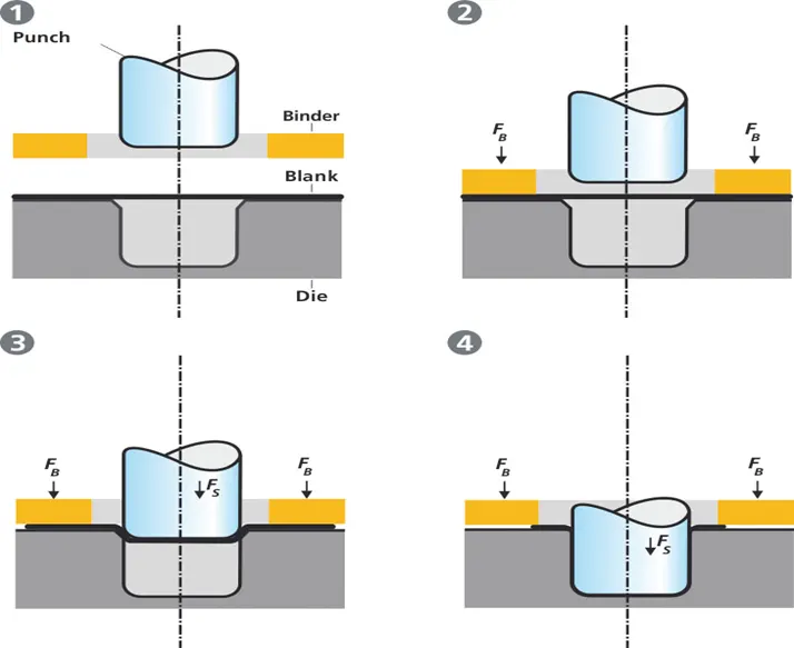
The deep drawing method is demonstrated in the figure. Punch, die, and binder are tools. After inserting the metal sheet blank, the plate holder in deep drawing closes. The sheet is then held in place between the binder and the die. This procedure slows the sheet's flow as it is drawn, preventing wrinkles from accumulating underneath the binder. The sheet is stretched over the die radius by the punch before being formed in the die. As a result, the punch force required to form is gradually raised all the way to the lower dead centre of the punch.
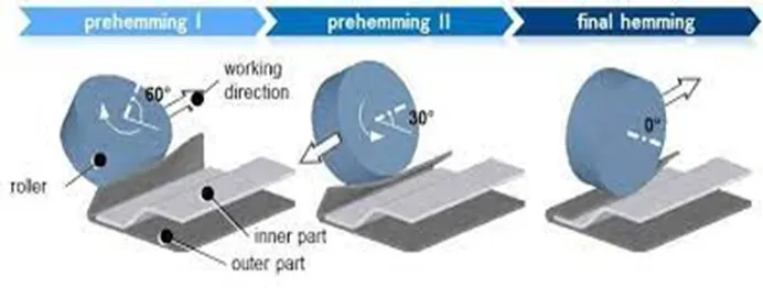
Whereas, hemming is a forming process where the sheet's edges are folded or folded over another portion to create a tight fit. Hemming procedures are typically applied to strengthen component edges, join parts together, and enhance part appearance. Since the hemming operation has an impact on the surface's look and surface quality, precision is crucial. During the hemming process, material deformations might result in dimensional changes and other parts faults. The flange may split or crease, the material may overlap in the corner sections, or the material may roll in. In order to both better understand the hemming process and to drastically cut down on the amount of "trial and error" cycles during test and production, it is crucial to use simulation tools. It is a secondary technique used in the assembly of automotive parts to link two sheet metal sections (the outer and inner) together after deep drawing, trimming, and flanging operations. The common components for this kind of assembly, hoods, doors, trunk lids, and fenders. For the hood hemming is done with the help of rollers, which travel around the edges of the hood gradually pressing the outer panel over the inner panel to join tightly.
Design methodology:
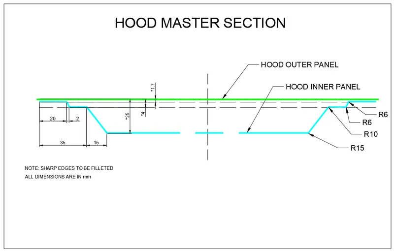
A hood consists a hood outer panel, hood inner panel, striker, and hinges. At first the design engineers will create class-A surface (outer panel) and master sections for inner panel.
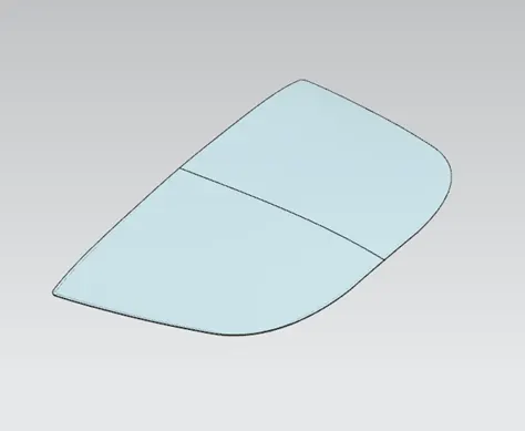
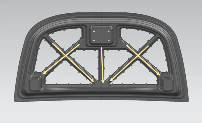
The hood inner panel is designed in such a way that when frontal collision happens the force will be distributed in the outside direction. This is achieved by designing embosses on the inner panel. The basic function of emboss is to increase strength and rigidity of the sheet metal. For the hood inner panel, the embosses should be directed towards the edges of the hood. Also, for the striker and hinges embosses are created to provide strength around those areas.
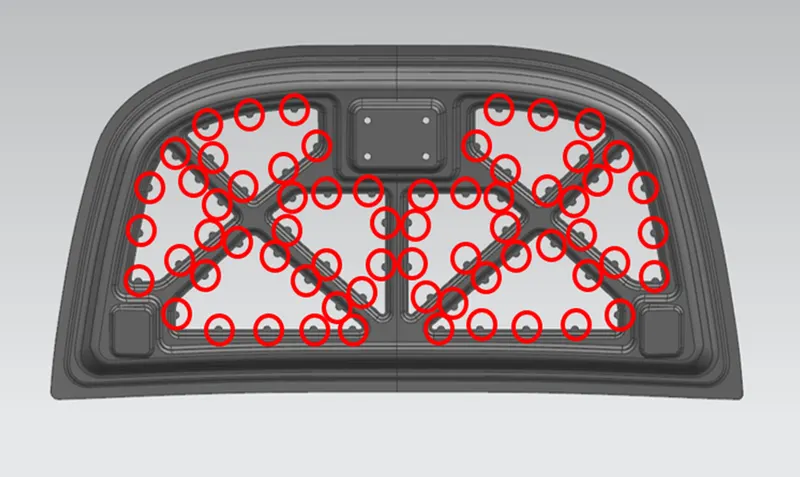
Around these embosses we must create mastic points for applying mastics between the inner and outer panels. The mastic sealant is an adhesive which eliminates the need of welding the panels and saves the outer surface from having bad surface finish. This also helps in reducing the overall NVH. These mastics are strategically placed as they have an 80mm diameter of influence around it. A minimum of 0.2mm clearance is given between the panels for mastics application.
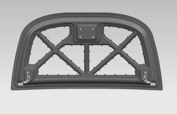
Hinges are attached at the rear ends of the hood. The other part is bolted inside the engine compartment. These hinges are positioned with the help of assembly constraints command in the assembly tab.
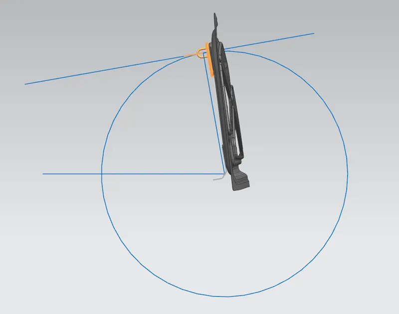
At the front centre edge of the hood, striker is attached for locking purposes. The striker is positioned with the help of hinge axis. The hinge axis is the axis that passes through the hinges around which the hood rotates. The striker axis should always be tangent to the circle drawn from the centre of the hinge axis for proper mating with the lock.
Finally, the hemming flange is created and hemming is designed around the inner panel. While designing th corners of hemming a minimum of 3 mm relief is given.
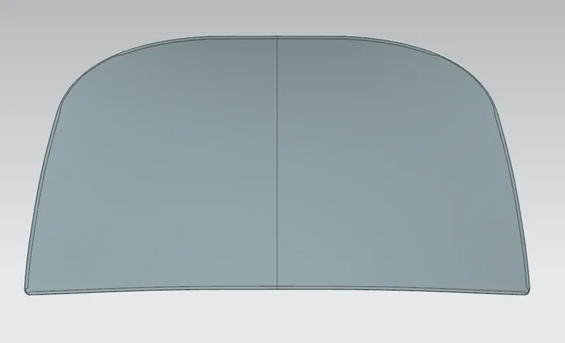
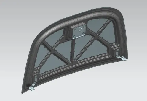
Following is the final assembly of the hood.
Conclusion:
From the given class-A surface (hood outer panel) and master sections the hood inner panel is designed with embosses and mastics data considering the thickness of sheet metal as 0.75mm. Hinges are positioned using assembly constraints. The striker is positioned tangentially to the circular trajectory of hood with the help of hinge axis. Hemming is created and the entire hood assembly is made ready.