Geometry Cleanup and Advance CFD Meshing of Turbocharger using Batch Mesh manager
Geometry Cleanup and Advance CFD Meshing of Turbocharger using Batch Mesh manager
I.Geometry : Please click here to find the geometry of cleaned turbocharger (Error rectified)
II.Aim
- To demonstrate the construction , working and funcitons of turbocharger
- To perform geometry cleanup of turbocharger using preprocessor tool ANSA
- To perform Surface Meshing , Layers creation and Volumetric Meshing of Turbocharger using batch mesh manager
- Create 5 to 7 Layers , by considering different Y+ Values
III. Theory :
A turbocharger, often simply referred to as a "turbo," is a mechanical device used in internal combustion engines to increase the amount of air delivered to the engine, thereby increasing the engine's power output. It is a type of forced induction system that compresses the incoming air, allowing more air to enter the engine's combustion chambers, which in turn allows more fuel to be burned and produces more power.
A typical turbocharger consists of two main components: a turbine and a compressor, which are connected by a common shaft. The turbine is usually driven by the exhaust gases from the engine, while the compressor is responsible for compressing the incoming air. As the exhaust gases flow over the turbine, it causes the turbine wheel to spin, which in turn drives the compressor wheel to compress the intake air. The compressed air is then forced into the engine's intake manifold, where it mixes with fuel and is ignited in the combustion chambers, resulting in increased power output.
Turbochargers are commonly used in automotive engines, as well as in other applications such as marine engines, heavy machinery, and aircraft engines. They are especially popular in high-performance and racing applications, where increased power output and efficiency are desired. Turbocharging can significantly improve an engine's performance by increasing its horsepower and torque, while also enhancing its fuel efficiency by allowing more air to be packed into the combustion chambers, resulting in better combustion. However, turbocharging also requires careful engineering and management of factors such as boost pressure, intercooling, and exhaust gas flow to ensure optimal performance and reliability. In this section we are going to see the construction , working and functions of turbocharger in detail
i.Construction of turbocharger :
There are different parts of turbocharger working together
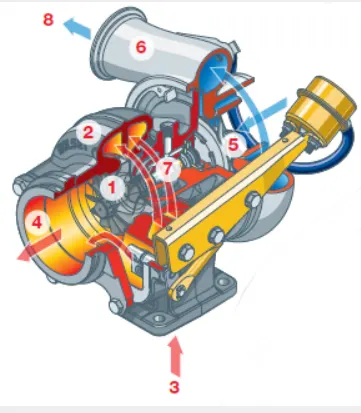
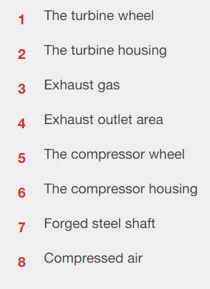
A turbocharger is made up of two main sections: the turbine and the compressor. The turbine consists of the turbine wheel (1) and the turbine housing (2). It is the job of the turbine housing to guide the exhaust gas (3) into the turbine wheel. The energy from the exhaust gas turns the turbine wheel, and the gas then exits the turbine housing through an exhaust outlet area (4).
The compressor also consists of two parts: the compressor wheel (5) and the compressor housing (6). The compressor’s mode of action is opposite that of the turbine. The compressor wheel is attached to the turbine by a forged steel shaft (7), and as the turbine turns the compressor wheel, the high-velocity spinning draws in air and compresses it. The compressor housing then converts the high-velocity, low-pressure air stream into a high-pressure, low-velocity air stream through a process called diffusion. The compressed air (8) is pushed into the engine, allowing the engine to burn more fuel to produce more power.
ii. Working of turbocharger :
The working principle of a turbocharger is based on the principle of forced induction, which involves compressing the incoming air to increase its density before it enters the engine. This allows the engine to burn more fuel and generate more power, without increasing the engine's displacement or size.
A turbocharger consists of two main components: a turbine and a compressor, which are connected by a common shaft. The turbine is located in the exhaust flow of the engine and is driven by the flow of exhaust gases, while the compressor is located in the intake system of the engine and draws in fresh air.
When the engine is running, the exhaust gases flow over the turbine blades, causing the turbine to spin. The spinning turbine is connected to the compressor through the common shaft, and as the turbine spins, it drives the compressor to also spin. The compressor draws in fresh air from the atmosphere and compresses it, increasing its density. The compressed air is then forced into the engine's intake manifold and mixed with fuel for combustion.
The increased density of the compressed air allows the engine to burn more fuel, resulting in a higher power output. This process is known as "forced induction" because the turbocharger forces more air into the engine than it would normally draw in naturally, increasing the engine's power and performance.
Modern turbochargers also incorporate other components such as intercoolers, which are used to cool the compressed air before it enters the engine, improving its density even further. Additionally, turbochargers are equipped with various sensors and controls to optimize their performance and protect the engine from potential damage due to over-boosting or other operating conditions.
In summary, the working principle of a turbocharger involves using the energy from the engine's exhaust gases to drive a turbine, which in turn drives a compressor to compress incoming air, resulting in increased engine power and performance.
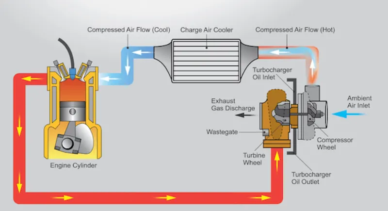
The turbine consists of a turbine wheel and the turbine housing whose purpose is to guide the exhaust gases into the turbine wheel. The kinetic energy of the exhaust gases gets converted into the mechanical after striking it on turbine blades. The exhaust outlet helps the exhaust gases to get exit from the turbine. The compressor wheel in the turbocharger is attached to a turbine with the help of steel shaft and as the turbine turns the compressor wheel, it draws the high-velocity, low-pressure air stream and converts it into high-pressure, low –velocity air stream. This compressed air is pushed into the engine with the more quantity of fuel and hence produce more power.
The waste exhaust gases of the engine are utilized to drive a turbine wheel, which is connected to a compressor wheel by a shaft. The compressor or air wheel sucks in air through the air filters and passes this into the engine.
As the waste gases are expelled from the engine, they are directed to the turbine or hot wheel of the turbo and so completes the cycle.
Capture:
Instead of escaping through the exhaust pipe, hot gases produced during combustion flow to the turbocharger. The cylinders inside an internal combustion engine fire in sequence (not all at once), so exhaust exits the combustion chamber in irregular pulses.
Conventional single-scroll turbochargers route those irregular pulses of exhaust into the turbine in a way that causes them to collide and interfere with one another, reducing the strength of the flow. In contrast, a twin-scroll turbocharger gathers exhaust from pairs of cylinders in an alternating sequence.
Spin:
The exhaust strikes the turbine blades, spinning them at up to 150,000 rpm. The alternating pulses of exhaust help eliminate turbo lag.
Vent:
Having served their purpose, exhaust gases flow through an outlet to the catalytic converter, where they are scrubbed of carbon monoxide, nitrous oxides, and other pollutants before exiting through the tailpipe.
Compress:
Meanwhile, the turbine powers an air compressor, which gathers cold, clean air from a vent and compresses it to 30 percent above atmospheric pressure, or nearly 19 pounds per square inch. Dense, oxygen-rich air flows to the combustion chamber.
The additional oxygen makes it possible for the engine to burn gasoline more completely, generating more performance from a smaller engine. As a result, the Twin Power engine generates 30 percent more power than a non-turbocharged one of the same sizes.
It follows the following process
- The engine’s air intake sucks in cool air and sends to the compressor
- The compressor compresses the incoming air and heats it up. It then blows out the hot air.
- The hot air cools down when passing through the heat exchanger and enters the cylinder’s air intake.
- The cold air burns inside the combustion chamber at a faster rate because of carrying more oxygen.
- Due to the burning of more fuel, the energy output will be bigger faster, and the engine will be able to send more power to the wheels.
- Hot waste gasses will leave the chamber and blows past the turbine at the exhaust outlet.
- The turbine rotates at a high speed and spins the compressor too as both are mounted on the same shaft.
- The exhaust gasses leave the car through the exhaust pipe. They waste less energy than an engine not having a turbocharger.
iii.Functions of turbocharger :
One of the surest ways to get more power out of an engine is to increase the amount of air and fuel that it can burn. One way to do this is to add cylinders or make the current cylinders bigger. Sometimes these changes may not be feasible -- a turbo can be a simpler, more compact way to add power.
Turbochargers allow an engine to burn more fuel and air by packing more into the existing cylinders.
So turbo chargers are used to generate more power from an engine. They basically provide boost to engines at high speeds.
Advantages :
In addition to the extra power, turbochargers are sometimes referred to as devices that offer “free power” because unlike a supercharger, it does not require the engine’s power to drive it. The hot and expanding gasses coming out of the engine are what power a turbocharger so there is no drain of the engine’s net power. Turbocharged engines are also not affected in the same way as naturally aspirated engines are when they go at higher altitudes. The higher in altitude a naturally aspirated engine climbs, the harder it becomes for it to get oxygen due to the thinning atmosphere. A turbocharger gets around this problem because it forces the oxygen into the engine’s combustion chamber, sometimes at 2 times the pressure of the atmosphere.
Turbochargers also improve the fuel efficiency of a vehicle however there is a misconception when it comes to turbocharged vehicles and fuel efficiency. Taking a naturally aspirated engine and slapping on a turbocharger on it will not improve fuel efficiency. The way that manufacturers improve fuel efficiency though turbocharging is by down-sizing an engine and then turbocharging it. For example, take a 2.5L inline-4 cylinder naturally aspirated engine and decrease the displacement to 1.4L and then turbocharger it. The smaller, turbocharged engine would still have the same performance figures (or slightly better) but because of the smaller displacement, it would also use less fuel.
Disadvantages :
Turbochargers have 2 main disadvantages when compared to a naturally aspirated or supercharged engine. Firstly is heat. Because a turbo is powered by hot exhaust gasses, it gets very hot. Sometimes under certain engine conditions, the turbocharger itself could start glowing red but of course this doesn’t happen in everyday driving conditions; it happens when the engine is pushed to its limits for a continuous amount of time. This is why you see some turbocharged sports cars with vents in the hood or down the side, it’s to try to get air moving through the engine bay and keep things cool.
The other big disadvantage of a turbocharger is something called turbo lag. Under certain conditions, whenever you put your foot down on the throttle, there is a delay between the time you demand power from the engine and the moment you actually start to feel it. That is turbo lag. When the engine’s speed is low, there isn’t a lot of exhaust gasses passing through the turbocharger so when you do demand power from the engine, the turbocharger turbine needs time to start spinning at an optimal speed. The effects of this can be reduced by downshifting to a lower gear but keen drivers can still sometimes notice the split delay in response.
So the next time you’re in a GM showroom, don’t overlook the turbocharged vehicles. They offer the same or more power as V6 or sometimes even V8 counterparts and they usually have better fuel economy due to the smaller displacement engine and less weight.
IV.Performing geometry cleanup of turbocharger using preprocessor tool ANSA :
1. Geometry imported :
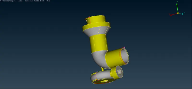
2.Units are in mm
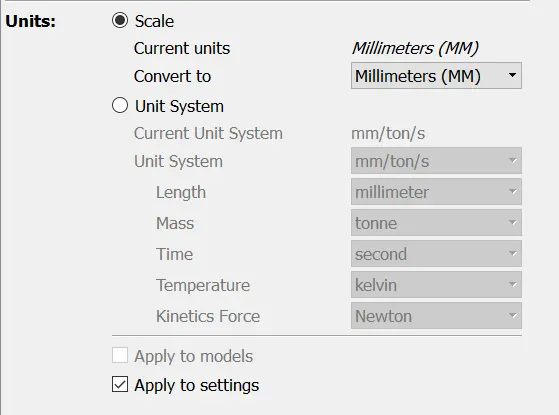
3.Resolution of geometry is fine
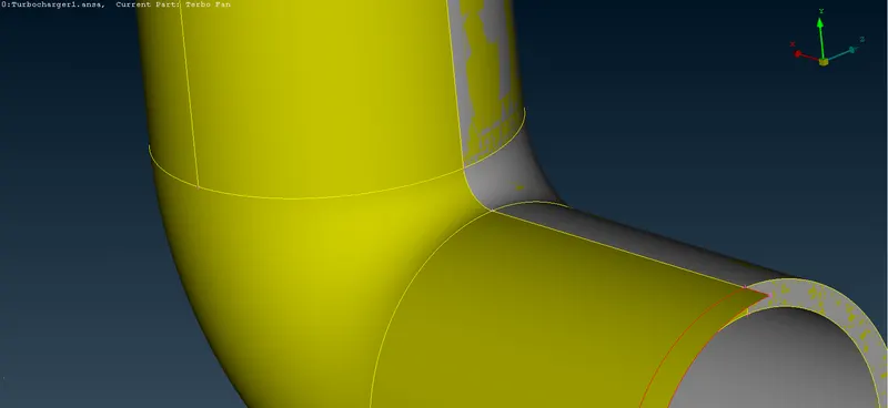
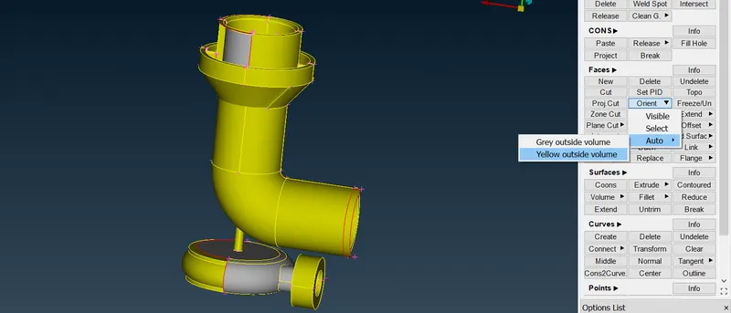
4. Orientation of the geometry is set as yellow outside using orient option in Faces secion
5. We can perform internal aerodynamic analysis or thermal analysis on the given turbocharger . Depending on the type of analysis , we can proceed further with geometry cleanup . That means for internal aerodyanamic analysis , we will be dealing with all the internal surfaces only. So we don't include external faces , thickness in this kind of analysis so geometry is also prepared in the same manner.
When it comes to thermal analysis, we would be rewuiring to deal with entire geometry to capture the way of dissipation of heat , so the geometry has to be created in such way , thickness also considered in such case .
6.In this case we are going for internal aerodynamic analysis . So we are implimenting the geometry cleanup approach correspondingg to the internal aerodynamic analysis . We will be removing external faces . which are obviously not involved with the type of analysis we will be doing in future .
7.If we turn on PID mode , we can see some kind of spreadout of PID. This can be termed as Glitching in ANSA . These will be overlapping faces.
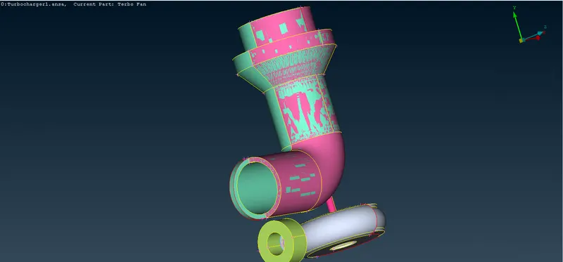
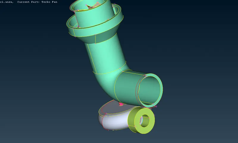
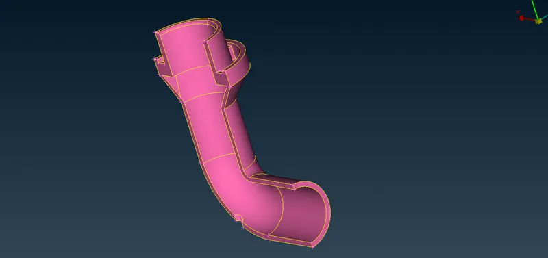
As we can see from the above picture, it can be clearly observed that, the Blue PID is the complete compressor casing and Pink PID is just half of the Casing , so we keep Blue PID and remove pink PID
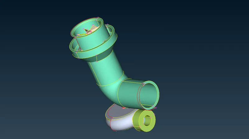
after deleting the pink PID overlapping error , glitch has been removed from our geometry
8.Extracting the faces which are going to be interracted with the fluid (As per internal aerodynamic analysis ):
In order to seperate internal face, we need to release internal cons such that it get rid of all other connections to external faces.
We have to release those internal CONS which have direct contact with external faces and delete the external faces using Delete PID Region .
These are the CONS Released for compressor casing :
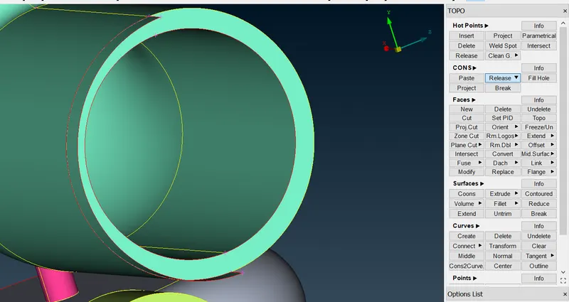
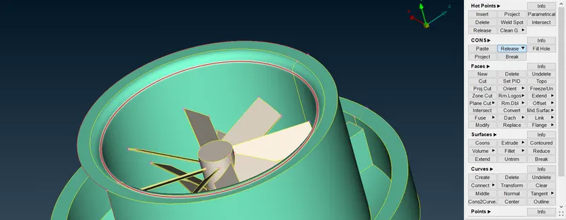
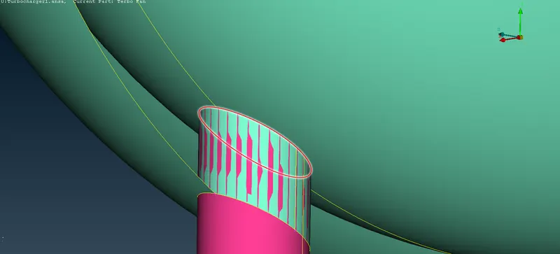
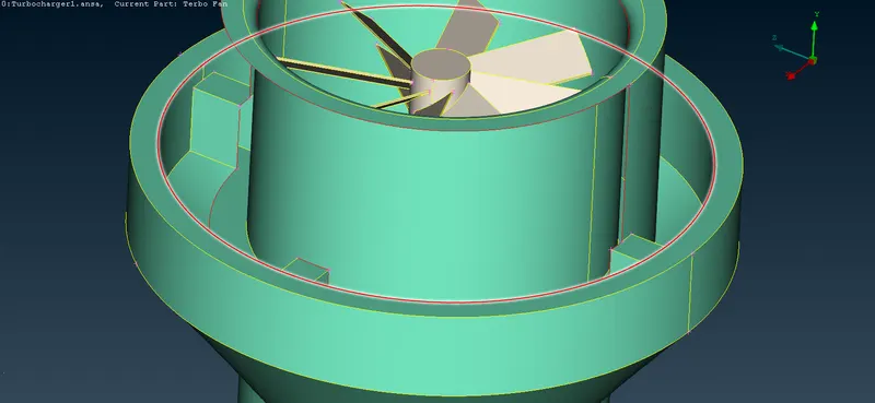
After releasing the CONS which are having direct contact with external faces , and if we are trying to delete external faces using PID Region , these faces are going to be deleted :
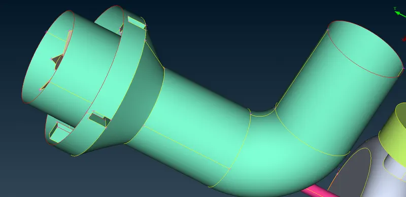
For turbine casing part we can manually delete the external faces :
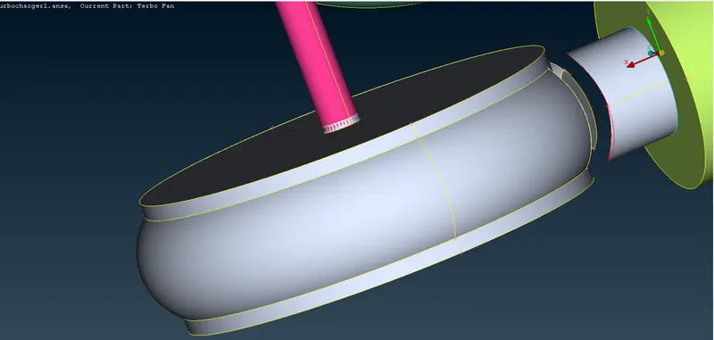
and for turbine inlet part we can select internal CONS and release them and delete external faces using delete PID Region option :
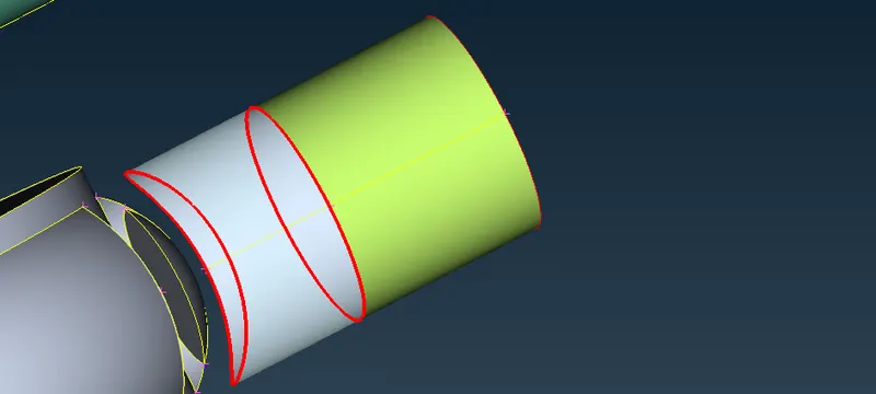
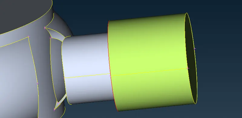
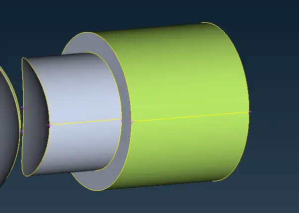 We can remove unnecessary faces by manually deleting :
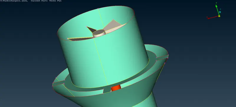
These gaps filled using fill hole option
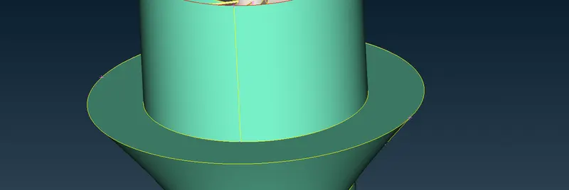
Closing the inlets and outlets using plannar option :
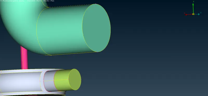
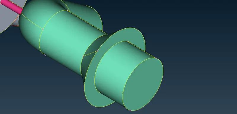
Unnecessary faces near the inlet of turbocharger have been deleted
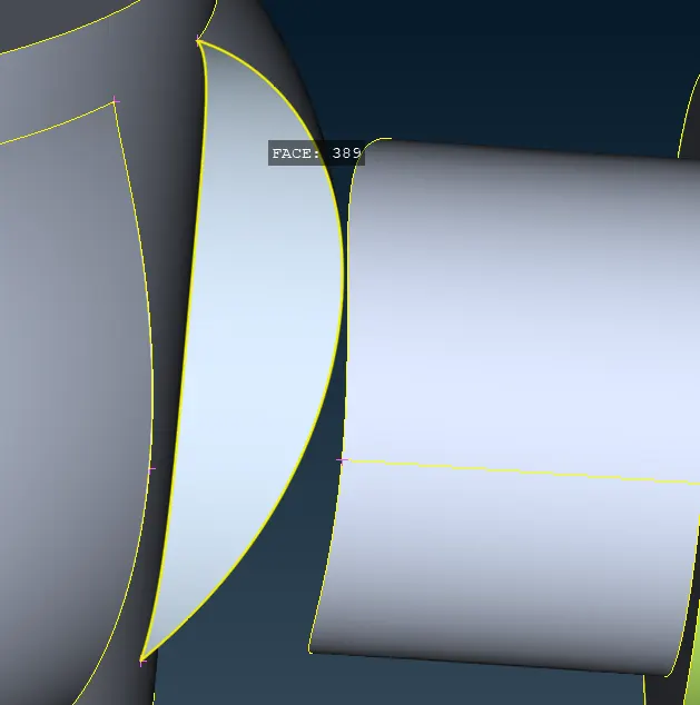
Filling the gap between outlet and turbing casing :
It can be done using projecting CONS by turning on the Connect with faces option
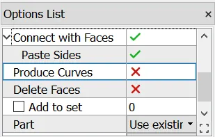
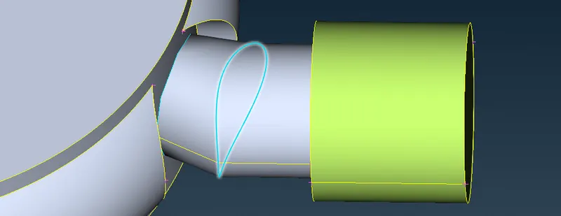
Changing the resolution of that :
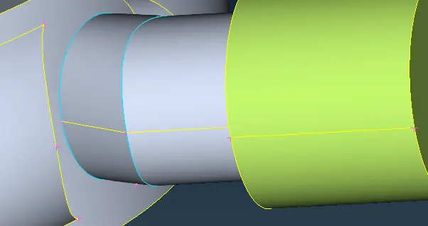
Creation of opening to inner part of turbine casing :
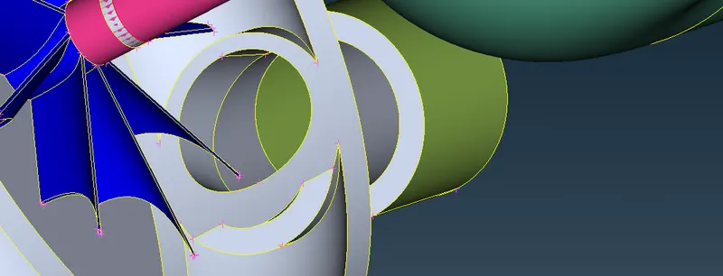
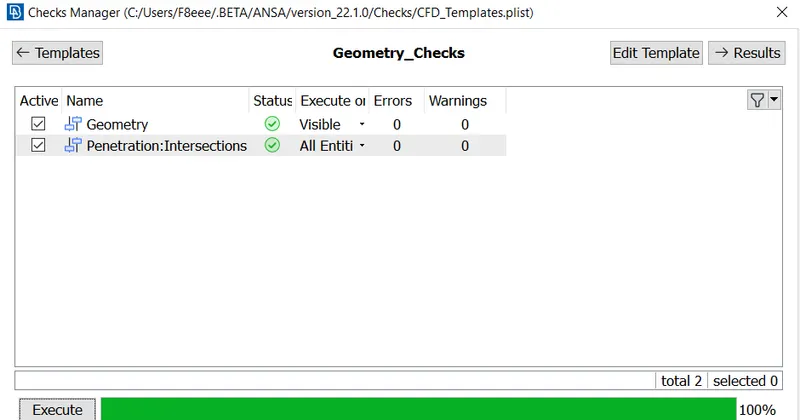
Geometry check :
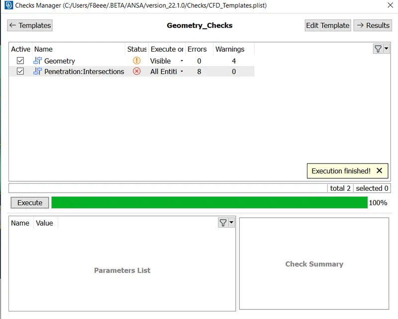
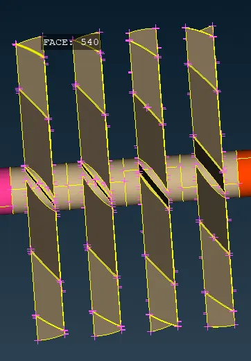
Cleaering of the intersection errors :
Those errors are due to overlapping of faces in shaft and blades , we should delete internal faces in between the shaft and make that as only one volume
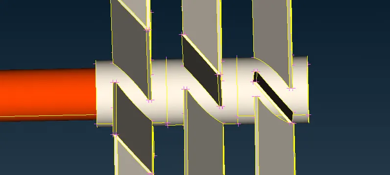
Overlappings deleted and new face created :
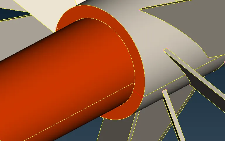
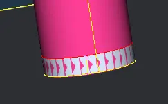
On bottom part of the shaft there is one overlap
The shaft is not going to be interracting with the air , so it can be deleted .
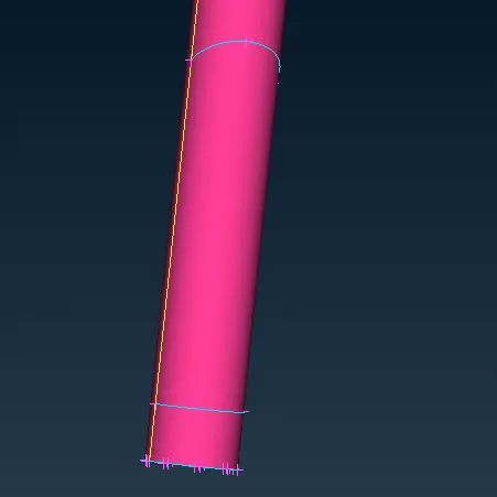
But we can know the exact part of the shat which has to be deleted by projecting the single CONS on to the shaft after deleting overlapping face
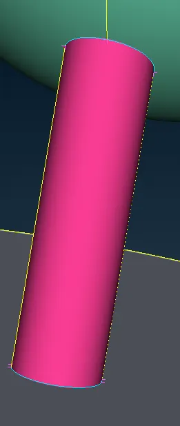
this part of the shaft can be deleted
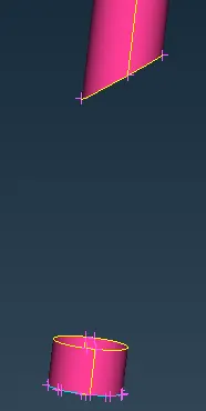
Removing the triple CON on the turbine blade :
We cant directly delete the top face of the blade as it also deletes the top faces of all the other blades also , in this case , we can use the cut option to define circular face on top or project the shaft surface on to the top of turbine blade .
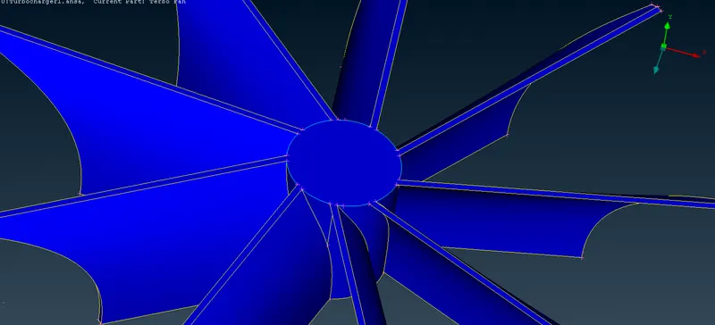
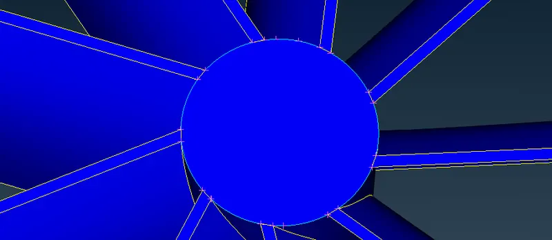 \
this top face can be deleted , it is not going to interract with the air
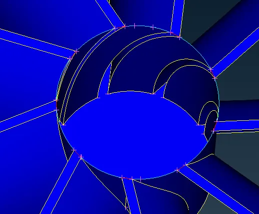
Now the all of the errors have been cleared
Batch Mesh Manager in ANSA
Overview of Batch Mesh Manager The Batch Mesh Manager in ANSA allows users to create, manage, and execute batch meshing tasks. It provides a user-friendly interface that streamlines the process of generating meshes for multiple models or parts simultaneously. The main objective of the Batch Mesh Manager is to enhance productivity by reducing manual intervention and optimizing the meshing workflow
Key Features:
Task Creation: The Batch Mesh Manager enables users to create and configure batch meshing tasks. Users can define the task settings, such as meshing parameters, element types, element size, and mesh quality criteria. These settings can be customized to meet specific requirements for each task.
Model Selection: Users can select multiple models or parts to be meshed within a batch. This selection can be done by browsing the file system or by utilizing ANSA's model management capabilities. The Batch Mesh Manager provides a clear overview of the selected models, allowing users to verify their choices before proceeding with the meshing process.
Parallel Meshing: The Batch Mesh Manager leverages the parallel processing capabilities of ANSA to enhance efficiency. It automatically distributes the meshing tasks across available processing cores or machines, enabling simultaneous meshing of multiple models. This feature significantly reduces the time required for generating meshes, particularly when dealing with large and complex models.
Mesh Quality Control: ANSA's Batch Mesh Manager incorporates robust mesh quality control mechanisms. It allows users to set criteria for mesh quality, such as element shape, aspect ratio, skewness, and size variation. The manager identifies and flags meshes that do not meet the defined quality standards, enabling users to review and refine them if necessary.
Task Monitoring and Reporting: The Batch Mesh Manager provides real-time monitoring of meshing tasks. Users can track the progress of individual tasks, view log files, and identify any errors or warnings encountered during the meshing process. Additionally, the manager generates detailed reports summarizing the meshing results for each model, including mesh statistics, element quality metrics, and any identified issue
Benefits of using Batch Mesh Manager 4.1 Improved Productivity: By automating the meshing process and enabling parallel meshing, the Batch Mesh Manager significantly reduces the time and effort required to generate meshes for multiple models. It allows users to focus on other tasks while the manager handles the repetitive and time-consuming meshing operations.
Consistency and Standardization: The Batch Mesh Manager ensures consistency and standardization in meshing practices by applying predefined meshing settings across all models in a batch. This eliminates the inconsistencies that can arise when different users apply their own meshing preferences, thereby enhancing the overall quality of the meshing process.
Error Identification and Correction: The Batch Mesh Manager's ability to flag meshes that do not meet the defined quality standards helps users identify potential issues and errors in the meshing process. This feature allows for timely corrective actions, resulting in improved mesh quality and subsequent analysis accuracy.
Scalability: The Batch Mesh Manager is designed to handle large-scale meshing tasks efficiently. It can effectively manage batches containing hundreds or even thousands of models, allowing users to take full advantage of ANSA's parallel processing capabilities and generate meshes at scale . The Batch Mesh Manager in ANSA is a powerful tool that automates and optimizes the meshing process, significantly improving productivity and quality in pre-processing tasks.
Procedure :
1. To mesh the turbocharger model using batch mesh reactor first we should be assigning the PIDs
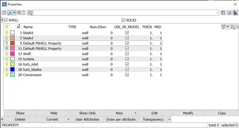
2.Before going for meshing we need to make sure that there would not be any geometrical and intersection errors ,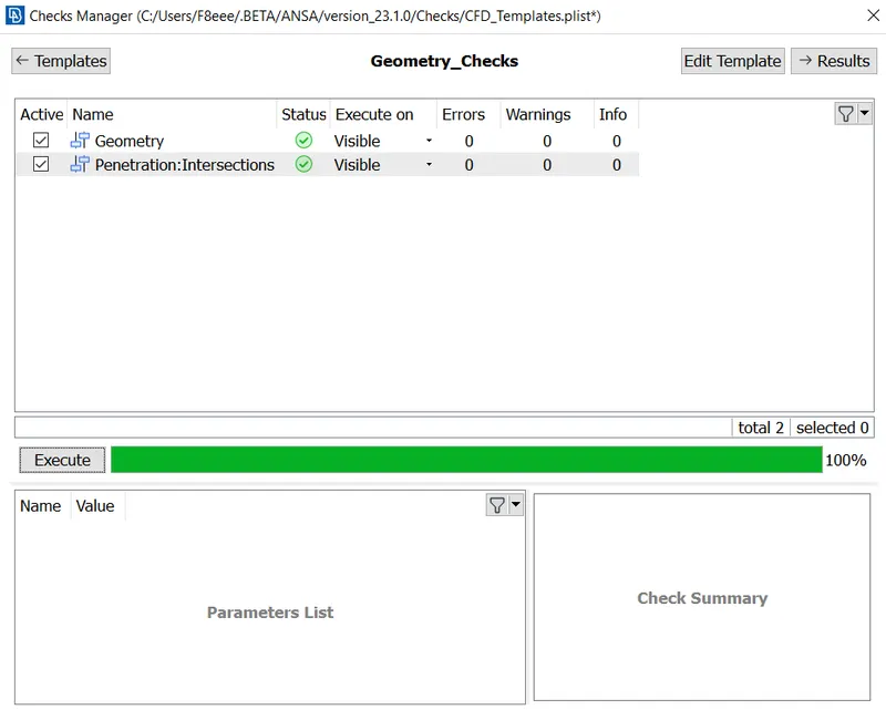
3. Actual process of meshing would be Surface meshing , creation of layers and volumetric meshing
4.Creating meshing scenario :
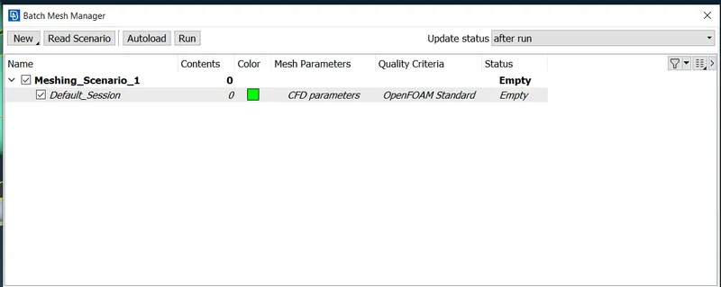
5. Providing target length for the ones which are require lower target length .
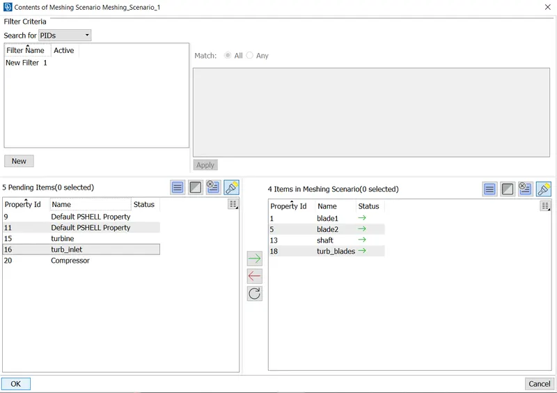
6. Now the contents can be seen 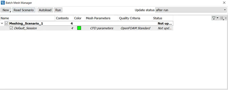 7.meshing inputs were given now as these are shaft and blades we give less target length . maximum target length and minum target length would be 1.5 and 0.5 mm respectively
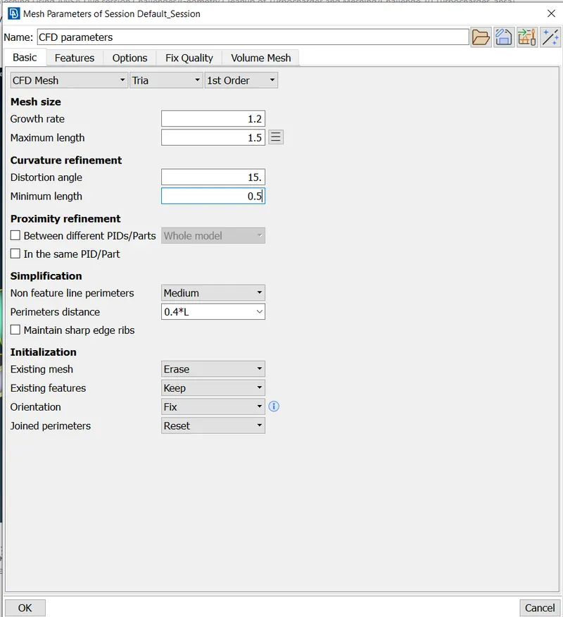
8. Based on our target lengths we can give the meshing scenarios
Now creating scenarios for other PIDs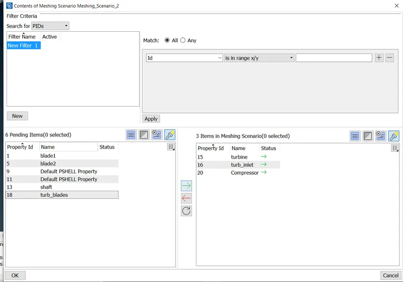
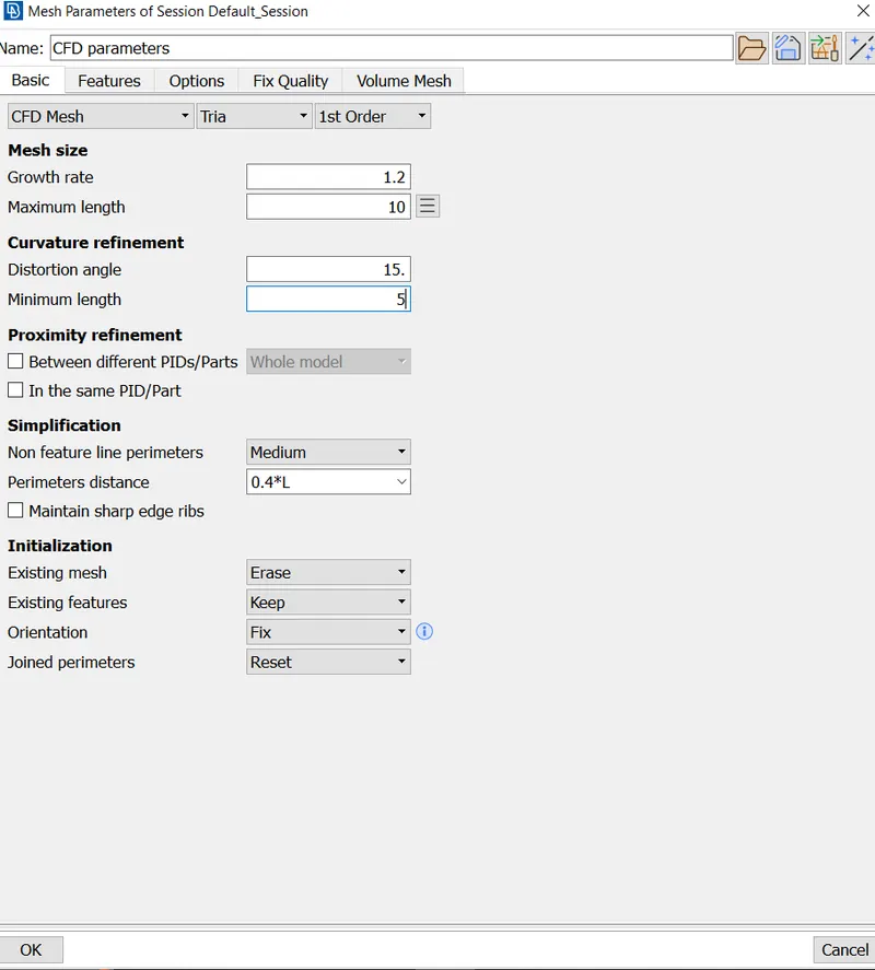
9. we give maximum target length as 10 mm and minimum target length ass 5 mm and triangular elements.
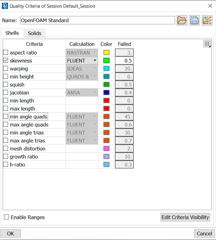
10.Defining quality criteria for both of the sessions:-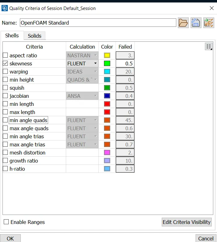
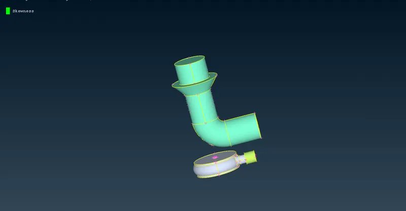
11.Now we have to create the layers scenario
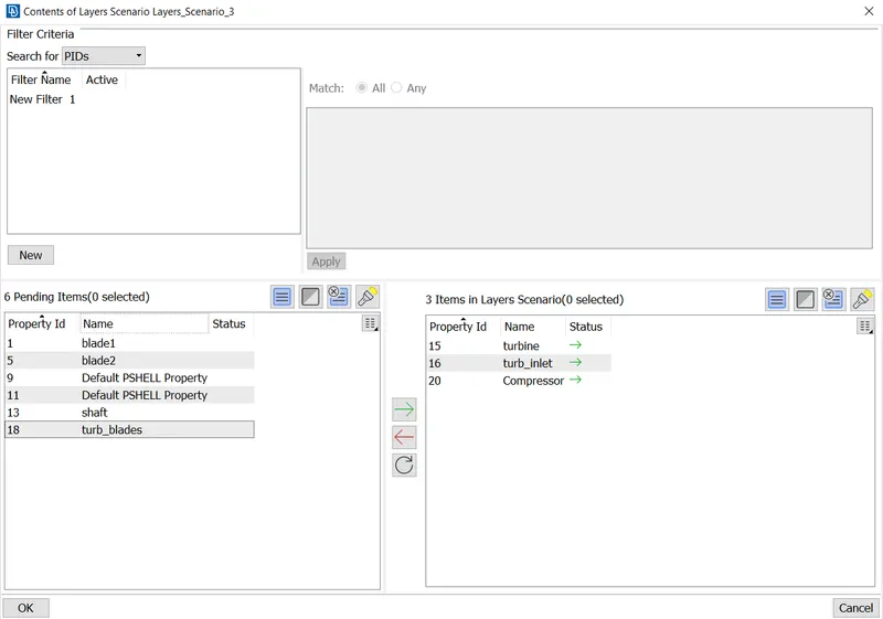
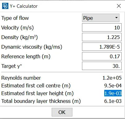
We will create layers by choosing velocity and Y+ values of choice
we are dealing with the internal flow so we can take pipe plate as pipe flow and
Velocity as 10m/s
Reference length 0.17m
Target Y+ is 30
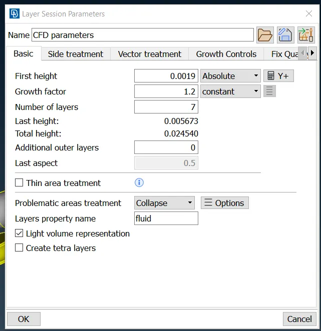
we are going to create 7 layers
by taking initial layer height from the Y+ calculation
These are the layer selection parameters:-
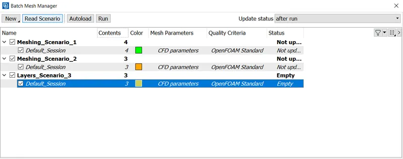
12. Creating Volume Scenario :-
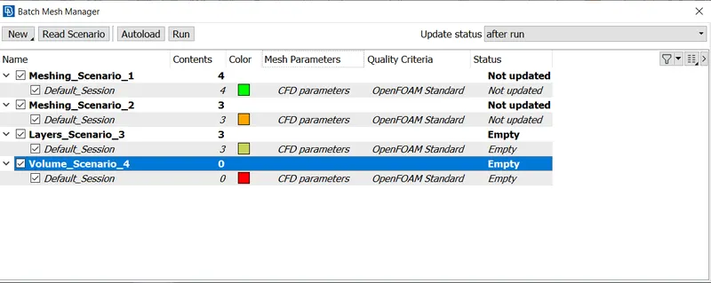
Usually after creating volume scenarios from the tabe we will not be able to find any content .It will be only visible once after we finish the surface meshing
but when we hit run all of the scenarios volume can be captured automatically and this kind of tool will be helpful for us in Performing CFD Meshing for bigger kind of geometries .
13. Running the scenarios :-
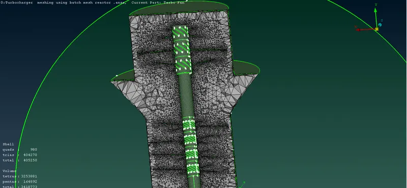
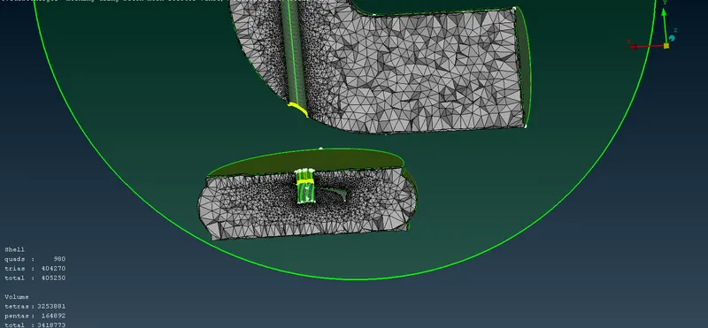
Volume has been created properly
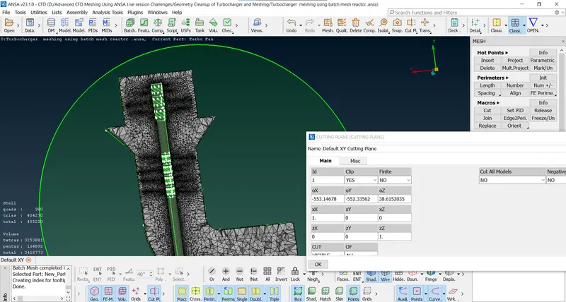
There are not any off elements also that means all the elements are following quality criteria which was set previously .In some cases off elements if those are less than 5% of the total element count than that can be ignored . those can not effect in our solving . 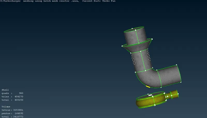
Number of cells :
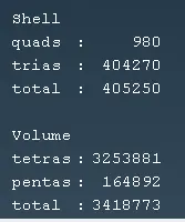
Conclusion :
1.The batch mesh manager has been used to mesh the turbo charger
Geometry Link :
https://drive.google.com/file/d/1WSCVelz9PXam1CwVYOjP8yJKbZR0XYp4/view?usp=share_link