Geometry Cleanup and Advance CFD Meshing of Pressure valve
Geometry Cleanup and Advance CFD Meshing of Pressure valve
I.Aim: To understand about the functions of pressure valve and to perform geometry cleanup of pressure valve using Pre processor ANSA .
To mesh the cleaned pressure valve using surface meshing and specifying the most suitable target length for the same
II.Theory :
1.Introduction :
Pressure valve can also be called as pressure relief vlave or Relief valve . As the name suggests it can be seen in almost every industry so as to release the pressure from the over pressurized region . These are important components in mechanical engineering systems that are designed to protect equipment and personnel from overpressure situations. They are used in various applications such as boilers, pressure vessels, pipelines, and hydraulic systems
2.Components of pressure valve :
These are the basic components of pressure valve in general :
- Body
- Inlet/Inlet Connection
- Disc/Disk
- Spring
- Seat
- Bonnet
- Overpressure Protection
- External Connections
- Body: The body of the pressure valve is the outer casing that houses the internal components. It is typically made of sturdy materials such as metal or plastic, capable of withstanding the pressure and temperature of the system it is installed in.
- Inlet/Inlet Connection: The inlet is the port through which the pressurized fluid or gas enters the pressure valve. The inlet connection is the interface between the pressure valve and the system from which the excess pressure needs to be relieved. It may include threads, flanges, or other types of connections, depending on the specific application and system requirements.
- Disc/Disk: The disc, also referred to as the disk, is the movable component of the pressure valve that opens or closes to control the flow of fluid or gas. It is typically made of metal or other suitable materials and is held in place by a spring or other means. When the pressure inside the system exceeds the set point of the pressure valve, the disc is lifted or displaced, allowing the excess pressure to escape.
- Spring: The spring is a critical component that provides the force to keep the pressure valve closed and determines the set pressure at which the valve opens. It is typically calibrated to a specific pressure range and is selected based on the requirements of the system. The spring can be preloaded or adjusted to achieve the desired pressure relief settings.
- Seat: The seat is the sealing surface against which the disc rests when the pressure valve is closed. It provides a tight seal to prevent fluid or gas from escaping when the pressure is within the normal operating range. The seat is usually made of durable materials such as metal or synthetic materials that can withstand the pressure and temperature of the system.
- Bonnet: The bonnet is the cover that encloses the internal components of the pressure valve, including the spring and disc. It provides protection from environmental factors, such as dust, dirt, and moisture, and is typically removable to allow for maintenance and adjustments.
- Overpressure Protection: Many pressure valves also include additional components for overpressure protection, such as a blowdown ring, which is a secondary relief mechanism that can help reduce the pressure in the system when the main pressure valve is fully open, or a diaphragm that provides additional sealing and protection against harsh fluids or gases.
- External Connections: Pressure valves may also have external connections for auxiliary functions, such as a drain connection to remove condensate or a pressure gauge connection to monitor the pressure in the system.
the design and configuration of pressure valves may vary depending on the specific application, system requirements, and industry standards. Proper selection, installation, and maintenance of pressure valve components are crucial to ensure their reliable and safe operation in mechanical engineering systems.
3.Working principle of pressure
The working principle of a pressure valve in mechanical engineering is based on the concept of relieving excess pressure from a system to prevent over-pressurization, which could lead to equipment damage, system failure, or safety hazards. Pressure valves operate as a safety measure by opening when the pressure in the system exceeds a predetermined set point, and closing when the pressure returns to the normal operating range.
The basic working principle of a pressure valve involves the following steps:
- Pressure Build-up: When the pressure in the system increases beyond the set point of the pressure valve, it exerts force on the sealing surface (seat) of the valve, pushing against the closing force of the spring and attempting to lift or displace the movable component (disc) of the valve.
- Opening of the Valve: As the pressure continues to rise and overcome the closing force of the spring, the disc of the pressure valve starts to lift or move away from the seat, allowing the excess fluid or gas to flow out of the system and escape through the valve's outlet or discharge port. This relieves the excess pressure and prevents it from exceeding the safe operating limits of the system.
- Pressure Relief: Once the pressure in the system drops back to the normal operating range, the closing force of the spring is sufficient to reseat the disc onto the seat, effectively closing the valve and stopping the flow of fluid or gas.
- System Stabilization: With the pressure valve closed, the system stabilizes, and the pressure remains within the desired operating range. The pressure valve is ready to operate again if the pressure exceeds the set point in the future, repeating the process to relieve excess pressure and protect the system.
It is important to note that pressure valves are typically designed and calibrated to specific pressure ranges and are selected based on the requirements of the system they are installed in. Proper selection, installation, and maintenance of pressure valves are crucial to ensure their reliable and safe operation in mechanical engineering systems.
In addition to the basic working principle described above, some pressure valves may also include additional features or mechanisms, such as blowdown rings, diaphragms, or external connections, to provide enhanced performance or protection against specific operating conditions or fluids. The specific working principle of a pressure valve may vary depending on its type, such as spring-loaded, pilot-operated, or balanced-bellows valves, as well as the industry standards and regulations that apply to the particular application.
4.Functions of Pressure Valve
The main functions of pressure valves in mechanical engineering include:
- Pressure Relief: The primary function of a pressure valve is to relieve excess pressure from a system. When the pressure inside a system exceeds the set point of the valve, it opens automatically to allow the excess pressure to escape, preventing any damage to the equipment or system. This is particularly important in systems that involve the storage or transport of fluids or gases under pressure, as overpressure can cause structural damage or even catastrophic failure.
- Safety: Pressure valves play a critical role in ensuring the safety of mechanical systems and personnel. By relieving excess pressure, pressure valves help prevent explosions, ruptures, or other catastrophic failures that may occur due to overpressure. This protects the equipment, surrounding environment, and personnel from potential harm.
- Regulation: Pressure valves also help regulate the pressure within a system. They can be set to specific pressure levels to maintain the desired pressure range within the system. This is crucial in systems where precise pressure control is required for optimal performance, such as in hydraulic systems or pneumatic systems.
- Protection against Vacuum: Pressure valves can also function as vacuum relief valves. In certain situations, such as during sudden cooling or when a vacuum is formed in a system, pressure valves can open to allow air or fluid to enter and equalize the pressure, preventing damage to the system due to vacuum-induced collapses or implosions.
- System Integrity: Pressure valves help maintain the integrity of the system by preventing overpressure situations that can lead to equipment damage, leaks, or other system failures. By regulating and relieving pressure, pressure valves help ensure that the system operates within its design limits, extending the lifespan of the equipment and reducing maintenance costs.
- Emergency Shutdown: In some cases, pressure valves are designed to act as emergency shutdown devices. For example, in a boiler system, a pressure valve may be set to a very high pressure threshold and will open automatically in case of a dangerous pressure surge, shutting down the system and preventing further damage.
- Alarm or Indicator: Pressure valves can also be equipped with alarms or indicators to alert operators or personnel when the pressure exceeds the set point. This provides a visual or audible warning, allowing for timely action to be taken to prevent any potential issues.
In conclusion, pressure valves are crucial components in mechanical engineering systems, serving various functions such as pressure relief, safety, regulation, protection against vacuum, system integrity, emergency shutdown, and providing alarms or indicators. Their proper selection, installation, and maintenance are critical for the safe and efficient operation of mechanical systems.
III.Geometry Cleanup of Pressure valve:
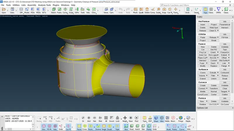
- The geometry is imported in to the ANSA
2.Initial Errors checked by checks manager
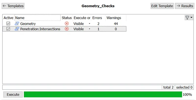
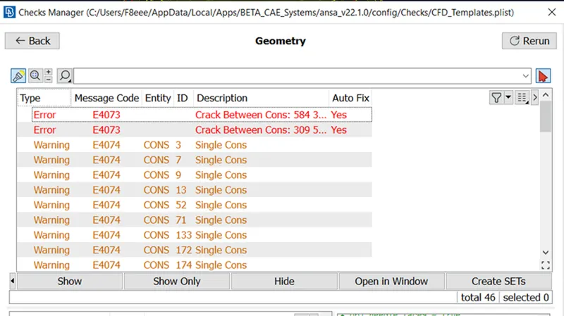
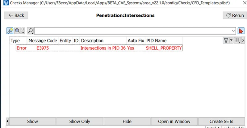
Here Single CONS appeared as warnings but we need to consider them as errors and they must be cleaned .
The above intersection errors are due to the intersection between
3.Before clearing the errors , gaps between faces has to be filled by creating new faces
New faces have been created where ever those are necessary Using appropriate face creating options in the ansa .
Faces can be created in 5 ways in ANSA
- CONS: used to create faces in the gaps by selecting CONS
- Fitted : Used to create faces in gap that fitts the hole
- Existing surface : Face created by taking neighbour surface as reference
- Plannar : Used to create faces In perpendicular sense
- Fill Hole : Fills the gap between faces
After creating the necessary faces inorder to have one water tight geometry if we checked for any kind of errors by running error check :
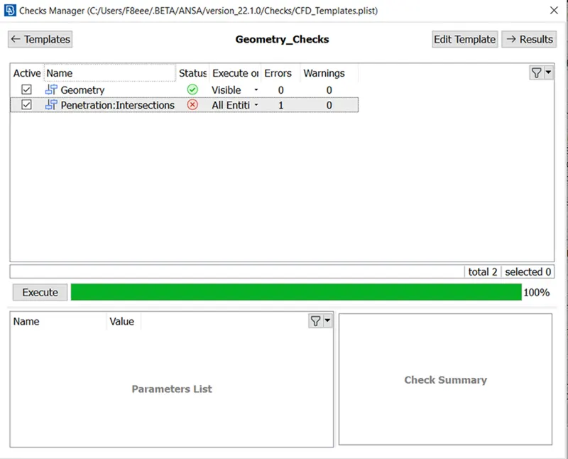
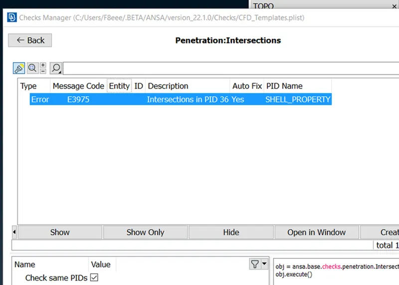
As we can see from the above , we can see there are no geometrical errors but there is one intersection error .
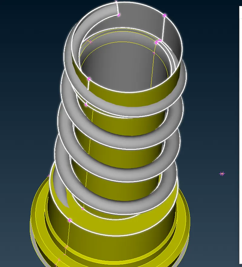
If we can closely observe that intersection error that is happened due to the intersection happened betweencoloumn and the spring .
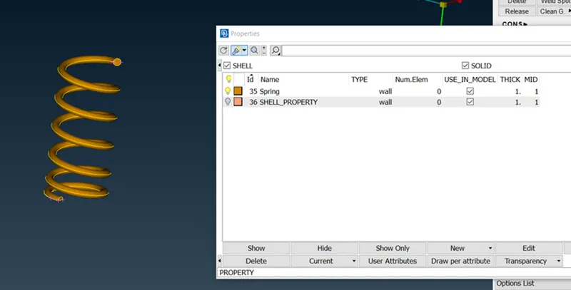
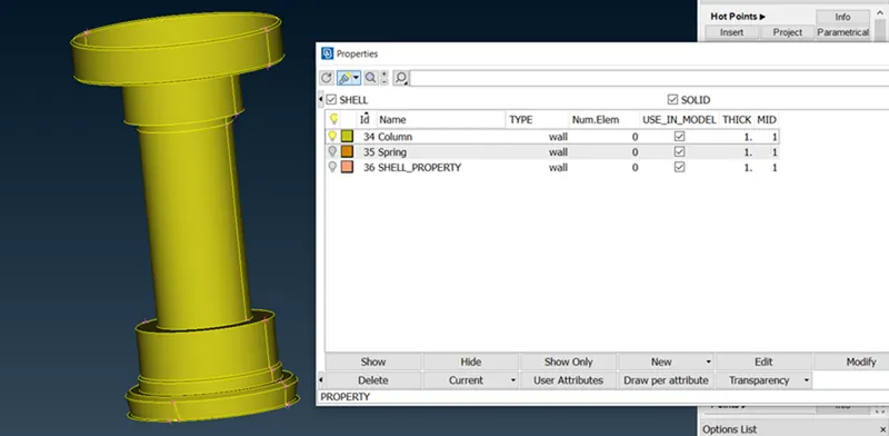
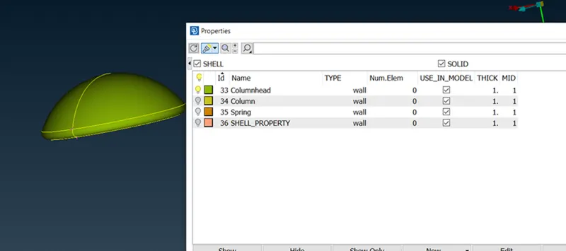
- Creation of PIDs :
Spring :
Column
Columnhead
Clearing Intersection errors between column and spring
If we can observe the isolated part of Spring and column , we can observe that , there are few intersections of spring and column
These can be created using Intersect Option . We need to select two faces and this feature identifies the intersected regions precisely and enables us to delete or keep the faces , in this way unwanted spring portions i.e, which are there in the inside part of the column are removed because in real sense this spring acts as suspension system and there is no point of having it in inside part of column
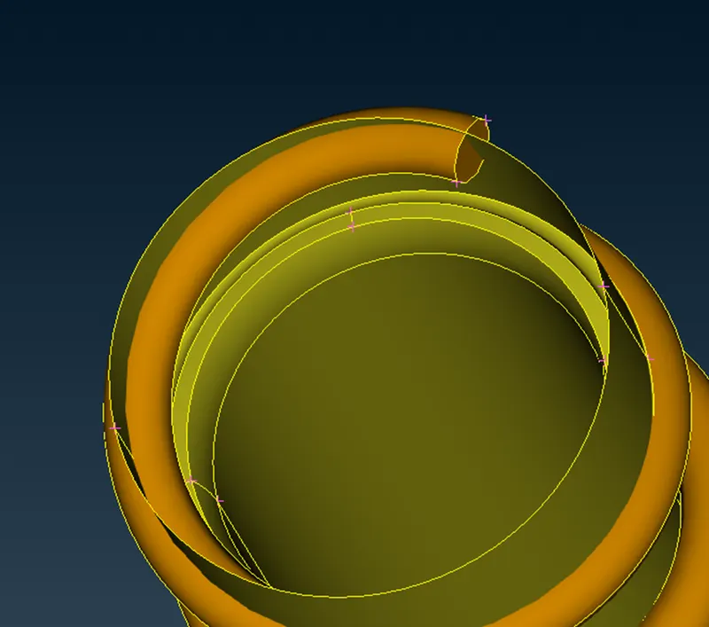
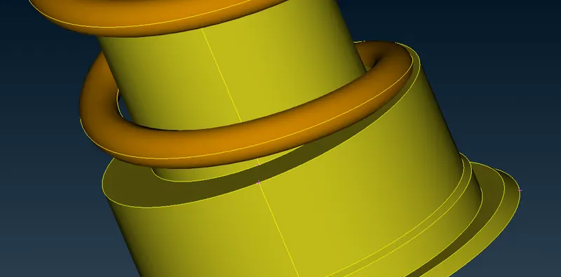
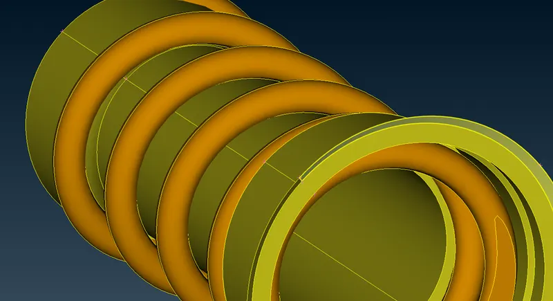
After performing intersection operation internal parts of spring have been deleted .
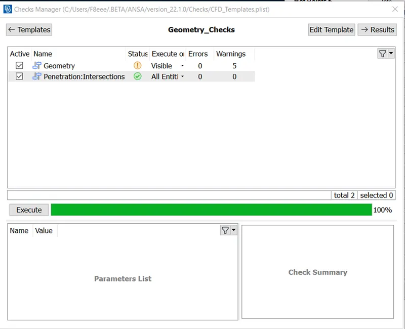
Few geometry errors appeared:
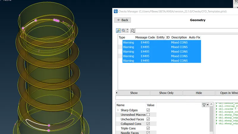
The appeared errors are Mixed CONS . These are due to sharp edges there in the geometry . These can be of three types Concave CONS , Convex CONS and Mixed CONS . These can be ignored during the geometry cleanup process. If we want to clean them also we need to modify the geometry or else their effect can be nullified using refined meshing in that particular region.
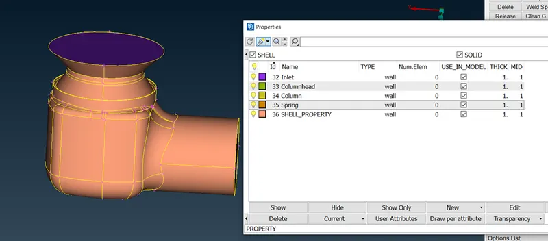
- Setting other PIDs
Inlet
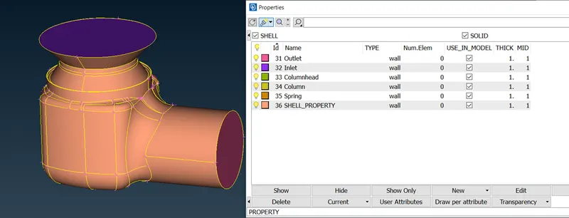
Outlet
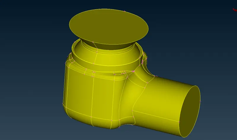
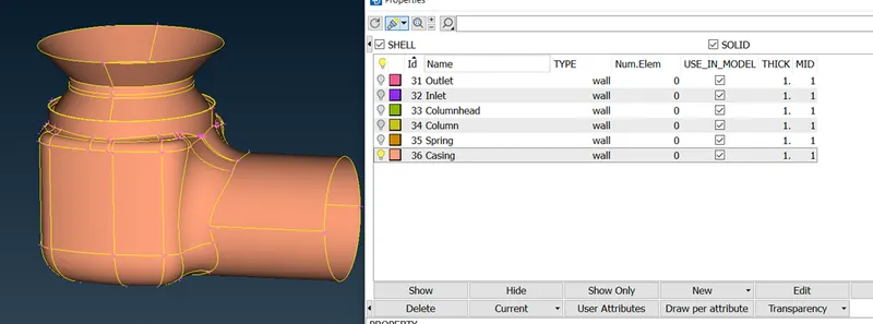
Casing :
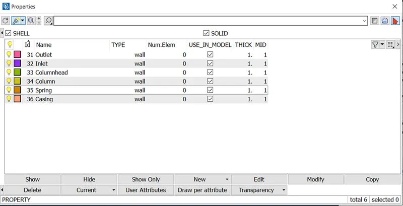
All of the PIDs have been assigned properly
Final geometry check :
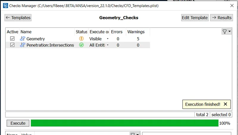
Conclusion :
In this way the geometry of pressure valve is made free from errors , now it is ready to be meshed .
Meshing:
Procedure :
Surface Meshing:
In this we can do the surface meshing by providing the spacing between the target lengths. For that in Perimeter option, Under SPACING Auto CFD option is there. After selection of AUTO CFD option, the Macro as well as Perimeter option is thrown. After selecting the geometry it will shown the Spacing parameter dialog box. It ask us to define the Minimum and Maximum Target Length. It is the tolerances that we can give for the target length. We have to instruct ANSA that within that range only we want to space the target length.
5mm of TARGET LENGTH:
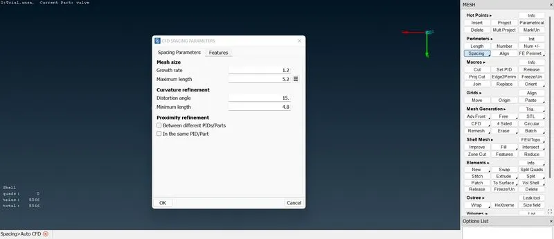
For 5mm of target length, I provide Minimum Target length as 4.8mm and Maximum target length as 5.2 mm. Then we have to go for MESH GENERATION OPTION, CFD -----> Visible. By clicking that it will mesh the part with predefined target length.
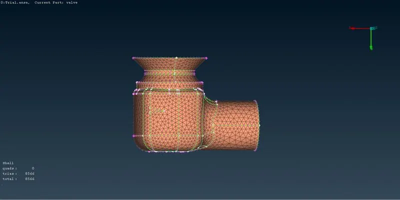
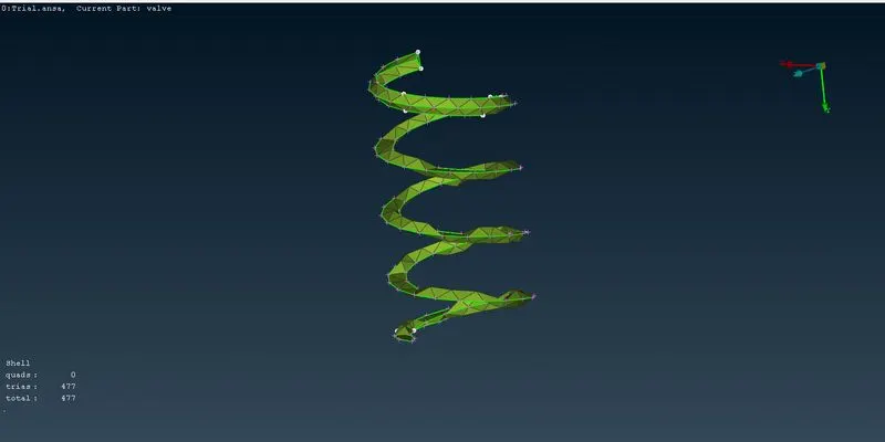
So for the 5mm of Target length, I got number of meshes as follows.
- Pressure Valve(Outer Casing)- 8566
- Column - 1201
- Spring - 477.
3mm TARGET LENGTH:
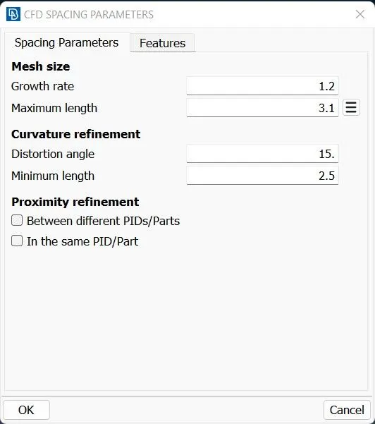
For 3mm of target length, I provide Minimum Target length as 2.5mm and Maximum target length as 3.1 mm. Then we have to go for MESH GENERATION OPTION, CFD -----> Visible. By clicking that it will mesh the part with predefined target length.
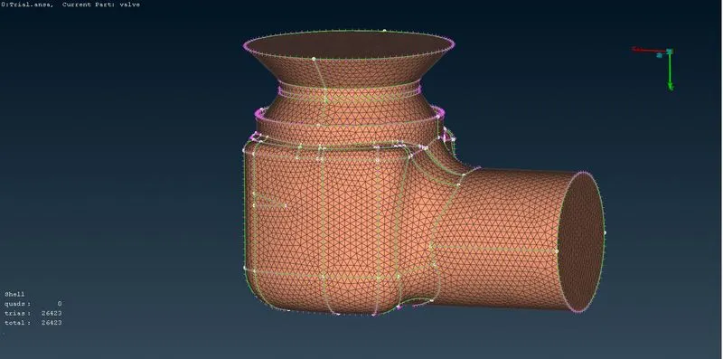
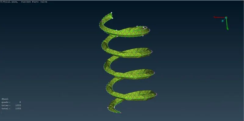
So for the 3mm of Target length, I got number of meshes as follows.
- Pressure Valve(Outer Casing)- 26423
- Column - 3042
- Spring - 1355.
1mm TARGET LENGTH:
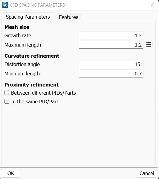
For 1mm of target length, I provide Minimum Target length as 0.7 mm and Maximum target length as 1.2 mm. Then we have to go for MESH GENERATION OPTION, CFD -----> Visible. By clicking that it will mesh the part with predefined target length.
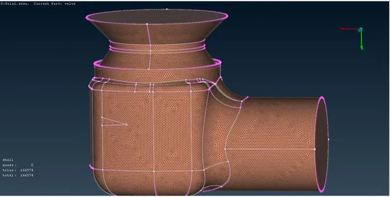
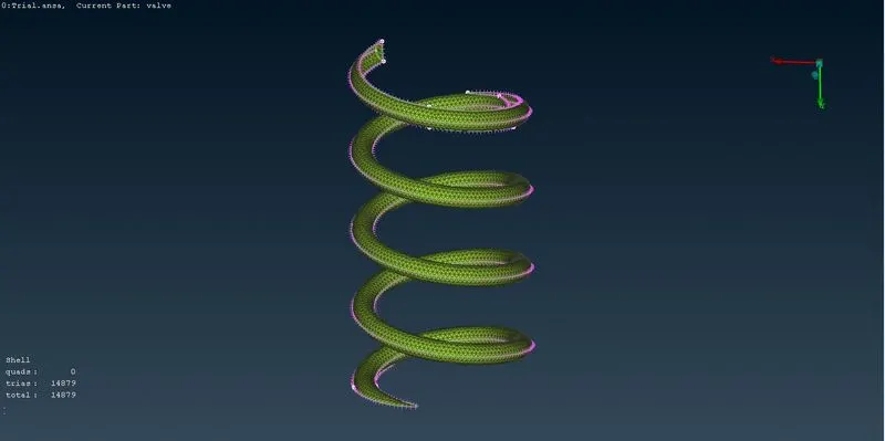
So for the 1mm of Target length, I got number of meshes as follows.
- Pressure Valve(Outer Casing)- 166574
- Column - 15565
- Spring - 14879.
So by doing the surface meshing by the 1mm, 3mm and 5mm. It is clearly seen that the well refined mesh is only obtained while choosing the target length as 1mm.
Volumetric Meshing:
After that we have to do the volumetric meshing. So by the geometry itself we have to clearly understand the fluid flow in the component. It is very clear fluid will flow inside the outer casing outer to the spring and column. So for this column we have to create the volumetric meshing where the fluid will flow.
For that we have to go for the VOLUME MESH DESK. Under that there is option called DEFINE, we have to select the option. The ANSA will detect the volume after we selecting this. For this geometry it shows two volume flow that is possible. We have to clearly select which one by understanding the fluid flow.
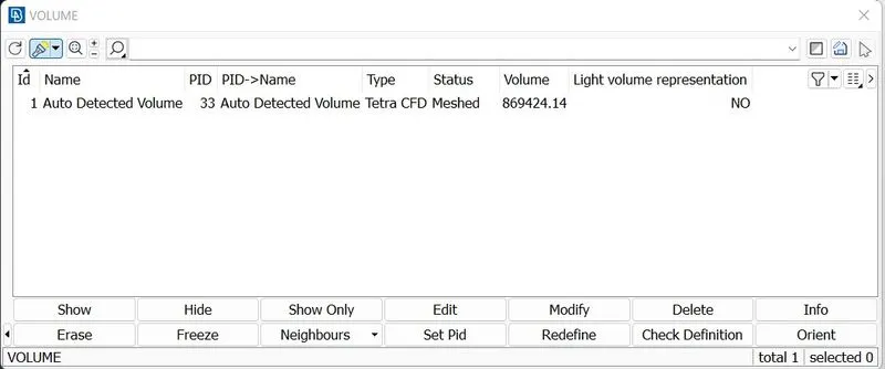
After selecting that we have to choose the type of the mesh. In this I choose TETRA CFD mesh and then we have to click remesh option. Then it will do the volumetric meshing.
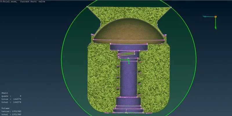
Total meshes in Volume is 1931940. Thus volumetrci meshing is done.
Geometry :
https://drive.google.com/file/d/1CWHq1JHY0q0eKV-o7y-OCnwCZVKsc8VH/view?usp=share_link
RESULT:
After the sort out of error three different target length of surface meshing is done. And by the results of the meshing Refined meshing is choosen and the volumetric meshing is done for that geometry