Gate Valve Parametric Study
AIM:-
To conduct a Parametric study on a Gate Valve Simulation changing the opening of the valve from 10%-80% and to calculate the flow co-efficient and flow factor and obtain the mass flow rate at every point.
INTRODUCTION:-
The gate valve is the fluid valve that opens by lifting the barrier gate from the path of the fluid flowing through a pipeline. It generally requires very little space and are and can be fitted along the pipe axis and they hardly restrict any fluid flow when they are fully opened. They are generally used to shut off the fluid flow inside a pipeline and also to control the fluid flow. When they are fully opened, they hardly restrict any fluid flow, thus offering very low flow resistance when fully opened. Gate valves are generally used for the pipe of diameters larger than that of 2" to the largest pipes. They are simpler to construct in large sizes. The gate can vibrate if it is in a partially open state. Generally, in pipelines with high pressure the gate valve opening can be quite difficult due to the high force exerted on the gate. So they are generally connected with a smaller bypass valve to release the pressure and then they are operated.
THEORY:
ANSYS CFD solvers are based on the finite volume method,
- The domain is discretized into a finite set of control volume.
- General conservation equations for mass, momentum, energy, species, etc. are solved on this set of control volumes.
- Partial differential equations are discretized into a system of algebraic equations.
- All algebraic equations are then solved numerically to render the solution field.
Initially, the process involves three major Categories,
Pre-Processing
- Geometry
- Mesh
- Physics
- Solver Settings
Solve
- Compute solution.
Post Processing
- Examine results.
Geometry
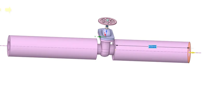
- The following Geometry is imported into the Space claim
- Then Each part is separated into different components.
- Using the move tool the gate valve is adjusted and parametrized.
- Then using the Volume extract tool the volume of the fluid is extracted.
- Then leaving the volume extract remaining part are suppressed for Physics.
Meshing
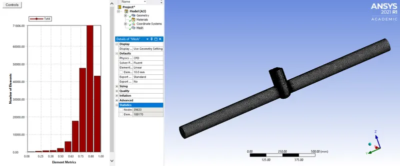
- Initially, we are going to assign a name selection to various components namely Inlet and Outlet.
- Then for meshing, we are going to be using the 10 mm element size.
Setup:-
- We are going to use Pressure Based solver.
- Under Steady-state conditions.
- We are going to use the K-Epsilon RNG model with the realizable conditions.
- Enable Gravity along the Z-axis as -9.81 m/s2.
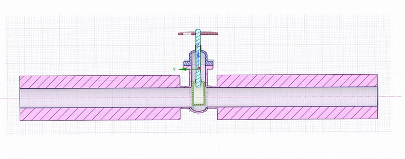
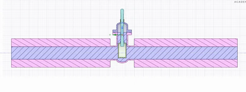
Gate Valve opened at 10% Gate Valve opened at 20%
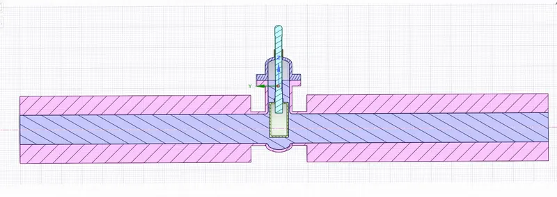
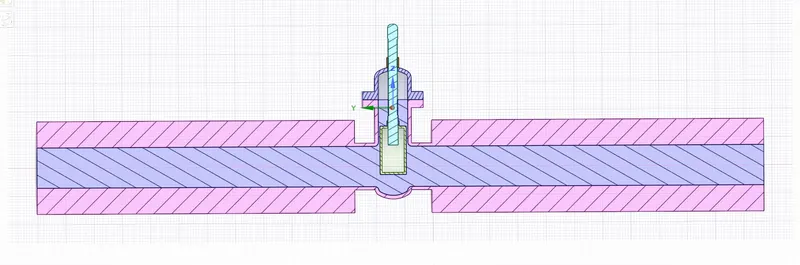
Gate Valve opened at 30% Gate Valve opened at 40%
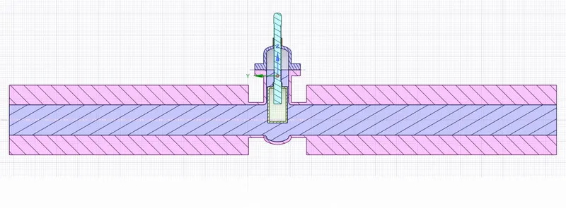
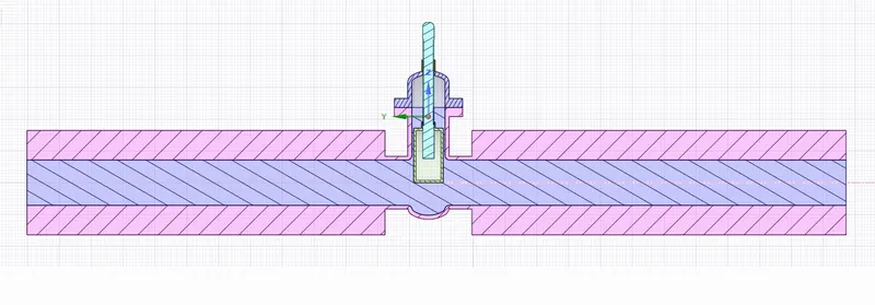
Gate Valve opened at 50% Gate Valve opened at 60%
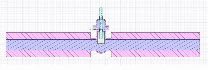
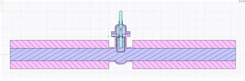
Gate Valve opened at 70% Gate Valve opened at 80%
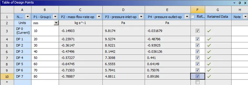
Result of Parametric Studies
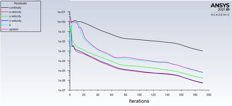
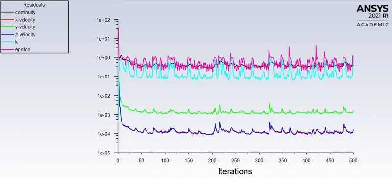
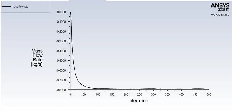
Scaled Residuals Mass Flow Rate
1) 10% Open
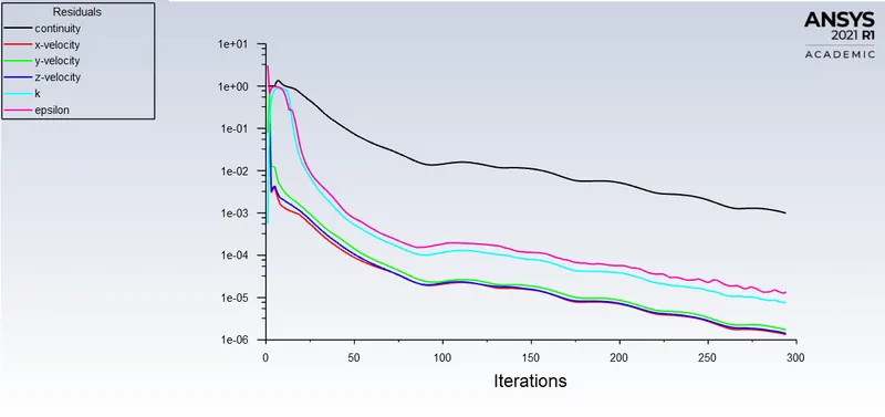
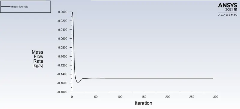
2) 20% Open
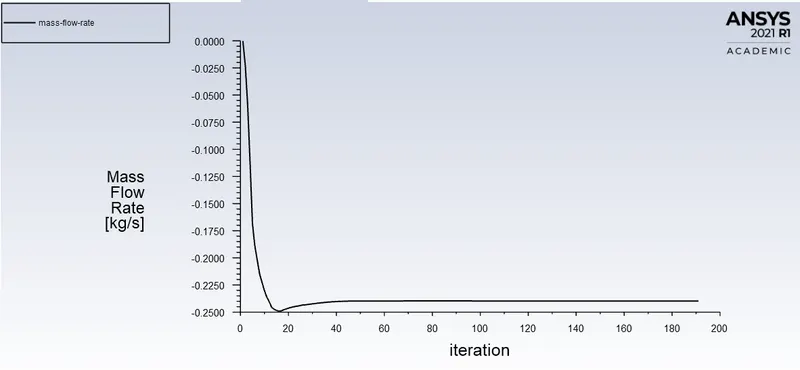
3) 50% Open
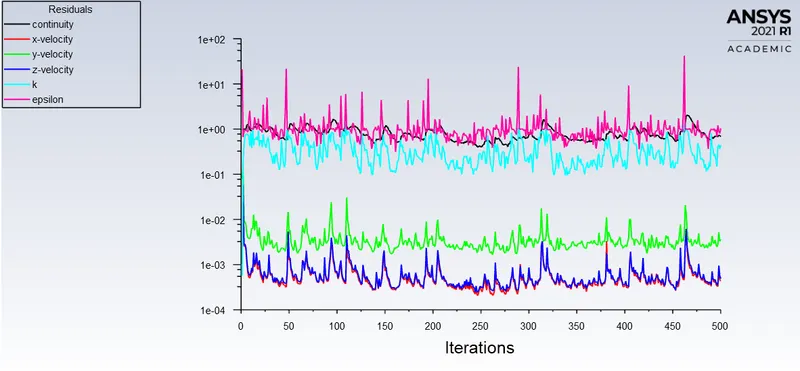
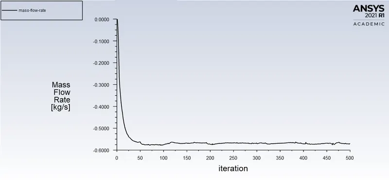
4) 80% Open
Flow Coefficient:
The flow coefficient of a device is a relative measure of its efficiency at allowing fluid flow. It describes the relationship between the pressure drop across an orifice valve or other assembly and the corresponding flow rate.
Mathematically the flow coefficient Cv (or flow-capacity rating of a valve) can be expressed as :
Cv, = Q*sqrt (SG/(P1-P2))
Q = rate of flow. (in US gallons)
SG = specific gravity of the fluid (for water = 1).
P1-P2 = pressure drop across the valve (expressed in psi).
In more practical terms, the flow coefficient Cv is the volume (in US gallons) of water at 60 °F that will flow per minute through a valve with a pressure drop of 1 psi across the valve.
The use of the flow coefficient offers a standard method of comparing valve capacities and sizing valves for specific applications that are widely accepted by the industry. The general definition of the flow coefficient can be expanded into equations modeling the flow of liquids, gases, and steam using the discharge coefficient.
Flow Factor:
The metric equivalent flow factor (Kv ; commonly used in Europe and Asia) is calculated using metric units :
Kv= Q*sqrt (SG/(P1-P2))
where
Kv = flow factor (expressed in m3.h-1.bar -0.5)
Q = flow rate (expressed in cubic meters per hour) SG = specific gravity of the fluid (for water = 1)
ΔP = differential pressure across the device (expressed in [bar]).
Kv can be calculated from Cv using the equation:
Kv = 0.865* C v
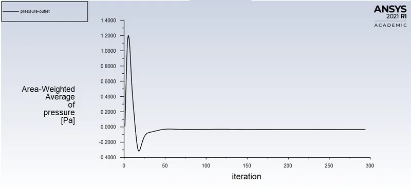
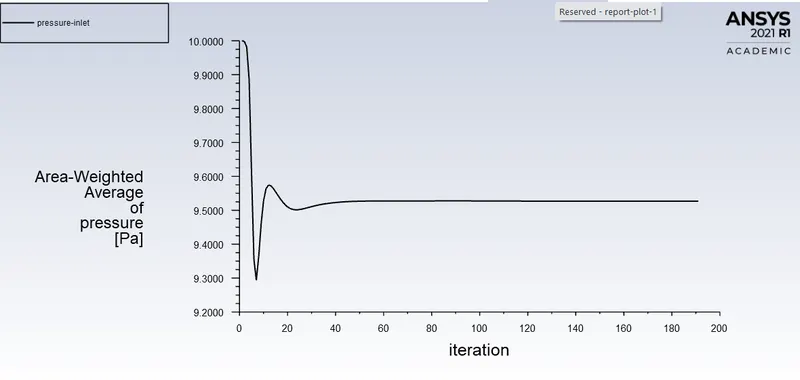
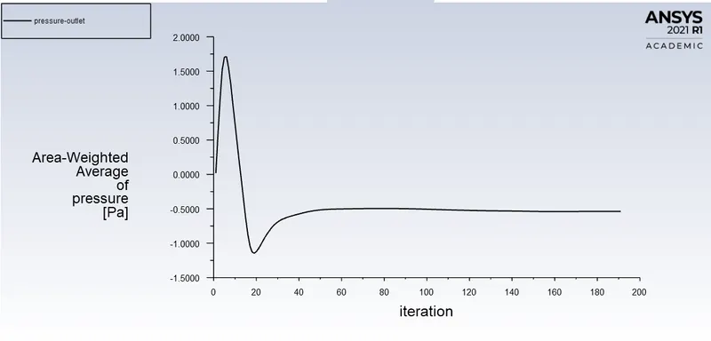
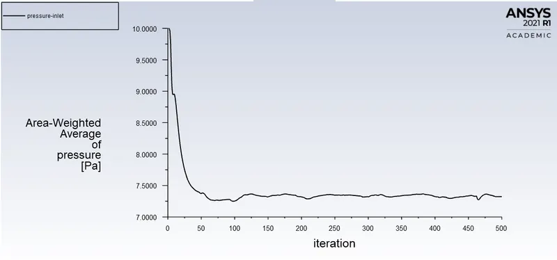
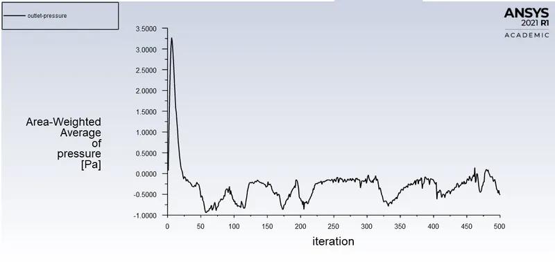
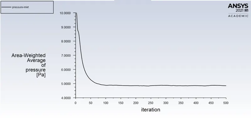
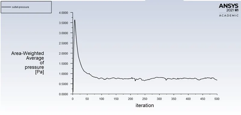
Pressure at INLET Pressure at OUTLET
1) 10% OPEN
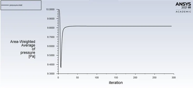
2)20% OPEN
3)50% OPEN
4)80% OPEN
RESULT:-
|
Opening Percentage (%) |
Mass Flow Rate (Kg/s) |
Flow Co-efficient (gal.min-1.lb-0.5.in) |
Flow Factor (m3.h-1.bar-0.5) |
| 10 | 0.14903 | 62.70 | 54.24 |
| 20 | 0.23971 | 104.93 | 90.77 |
| 30 | 0.36147 | 168.38 | 145.65 |
| 40 | 0.47496 | 219.53 | 189.90 |
| 50 | 0.57227 | 287.38 | 248.58 |
| 60 | 0.64745 | 350.40 | 303.09 |
| 70 | 0.71503 | 419.04 | 362.47 |
| 80 | 0.78887 | 519.81 | 449.64 |
Conclusion:-
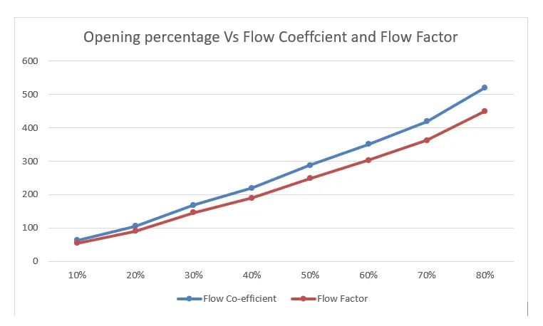
- Both Flow coefficient and flow factor increase with the increase in the percentage of valve opened.
-
When the valve is fully open, the Mass Flow rate and Flow Coefficient, and Flow Factor becomes maximum.
- From Post-processing, we know that velocity at midplane increases along with the opening percentage of the valve.
-
We can conclude from the observations that velocity in the first case is very low, As the opening or lift of the Gate Disc increases, the velocity of the flow increases.
-
We can observe that at the front or inlet side of the valve, the pressure is high. As flow passes through the valve opening, it decreases. And at the outlet, there are no restrictions to the flow, so pressure becomes 0.
-
Thus, parametric study helps to analyze the different positions of valve opening and gives the benefit to get easy and quick results.