Gate Valve Parametric Study
AIM:-
- To perform a parametric study on the gate valve simulation by setting the opening from 10 % to 80%.
- to obtain the mass flow rates at the outlet for each design point.
- To calculate the flow coefficient and flow factor for each opening and plot the graph.
- To discuss the results of the mass flow rate and flow coefficient.
EXPLANATION AND SIMULATION:-
We are using gate valve as the geometry and performed simulation by lifting the valve for different design points.
Geometry:-
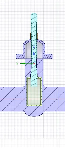
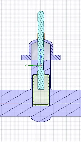
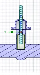
Gate valve is normally used to control the flow of the fluid by lifting the disc.
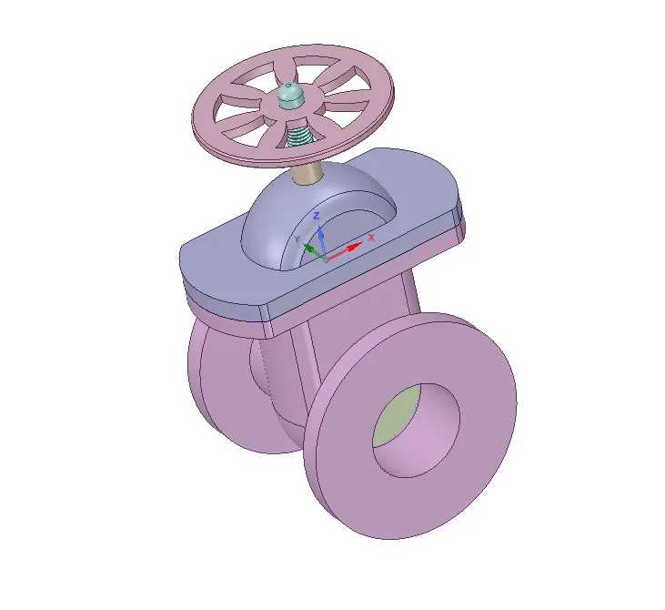
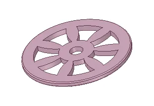
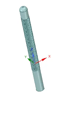
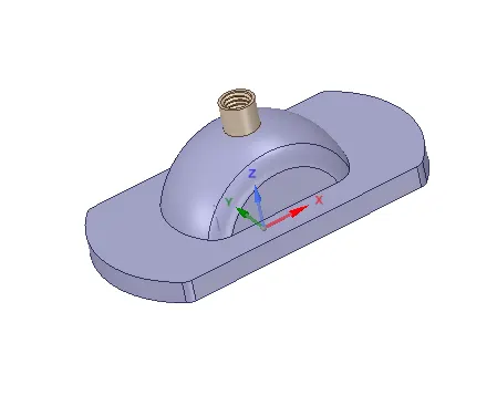
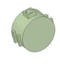
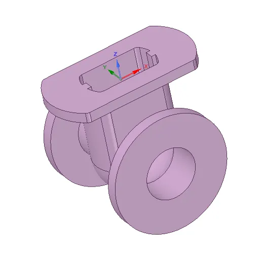
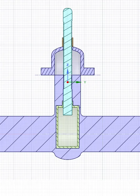
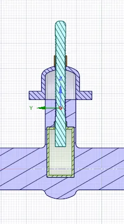
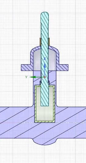
hand Wheel Spindle Bonnet Gate Disc Bottom
As we are intrested in the fluid volume inside the gate valve.
We have to extract the volume from solid volume using space claim.
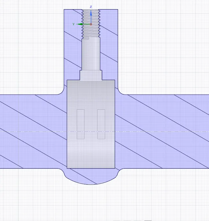
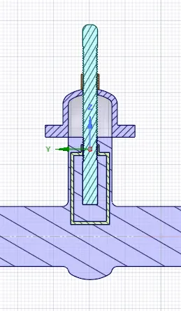
We are using volume extraction tool and extracting the volume by edges as shown below.
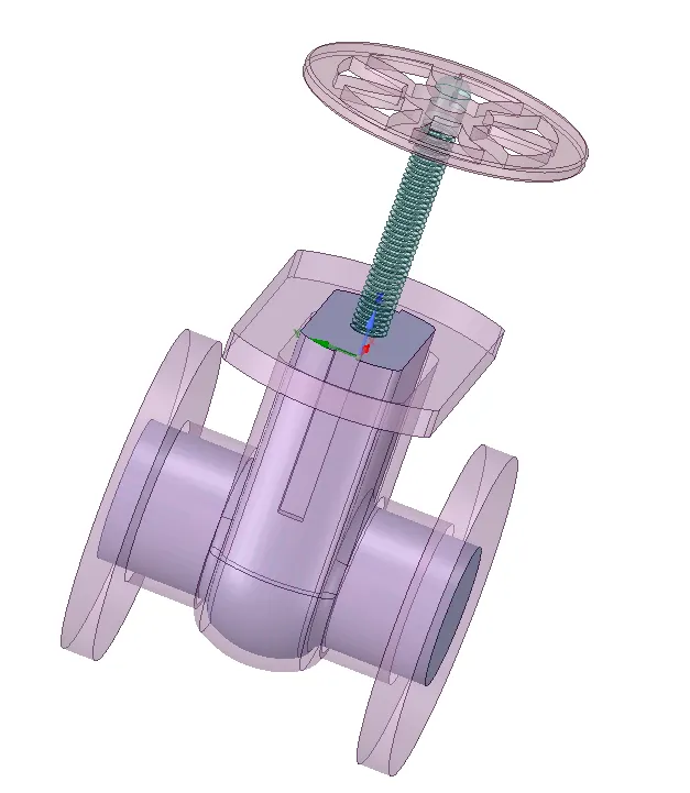
Now supress for physics for all the solid parts.
As we are doing a parametric study on this valve we gave to swtich on the parametric study in the space claim as below
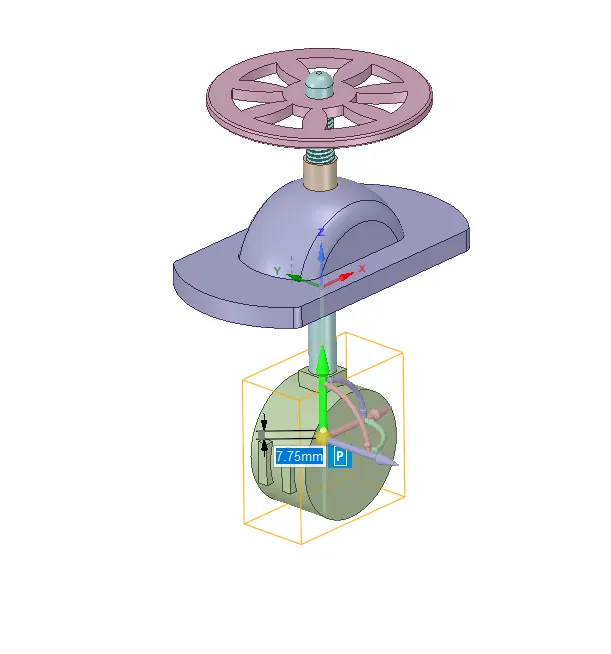
we can now change the dimensions or design points to lift the valve as required in the parametric case.
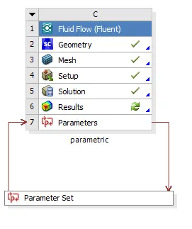
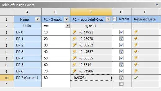
As we enter new design points and tick the "Retain" and set that particular design point as current required point or lift needed.
For evaluation you can check in the space claim whether your design point was updated. If the design point is updated and the fluid volume is mispalced or is not corresponding to the lift given by us,
Then we have to use 'update the volume body in context' option in the fluid volume. To get the results accurately we have to elongate or pull the sides of the inlet and outlet.
You can always verify the fluid volume by using the cross-section tool.
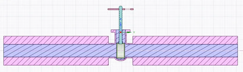
Now our geometry is ready to be meshed.
Meshing:-
We are keeping our mesh fine enough to capture the physics properly.
Meshing method used :- Triangular
Elment size:- 6mm
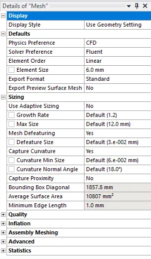
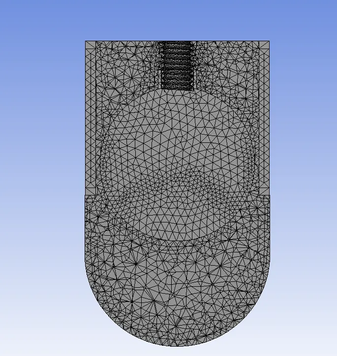
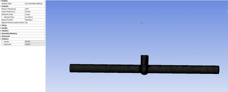
Make sure that the mesh is conformal.
Give the named section
Inlet and outlet at the opposite ends.
Fluent Setup:-
General:-
Pressure based absolue velocity and Steady state.
Turn on gravity (-9.81) in the negative z-axis.
Boundary conditions:-
Inlet:- Pressure inlet, 10pa
outlet:-Pressure outlet, 0 Pa
Wall:-Stationary wall, No slip
interior-volume:- interior.
Type of material:- Water-liquid.
Report created:- Mass flow rate at outlet
Note:- Make sure to click on created output parameter, to update this in the parametric study.
Viscous model:- k-epsilon- Realizable, Scalable wall Functions
We have selcted a turbulence model because the flow inside the pipe will have high Re as we are using 10 Pa as inlet pressure.
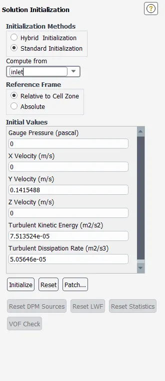
`Re = (rho*V*D)/mu`
density:-998.2
Velocity:-0.1415488
D:-0.1m
viscosity:- 0.001003
Re:-14087.14
therefore, the flow becomes turbulent.
We are using Standard Initialization from the inlet with 300 iterations.
We have created a plane in yz-direction.
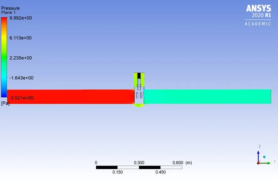
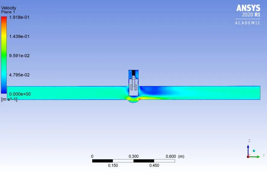
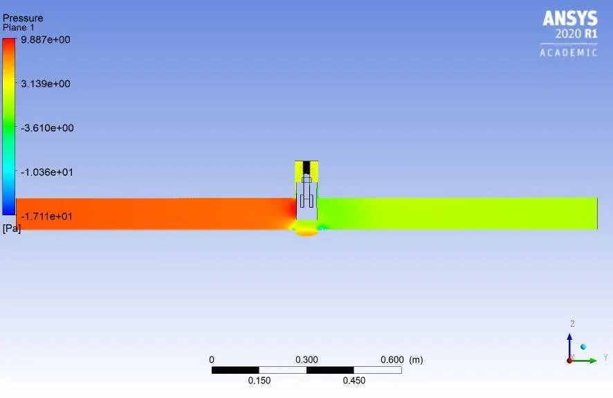
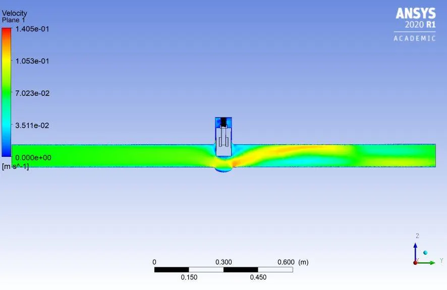
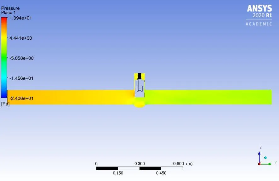
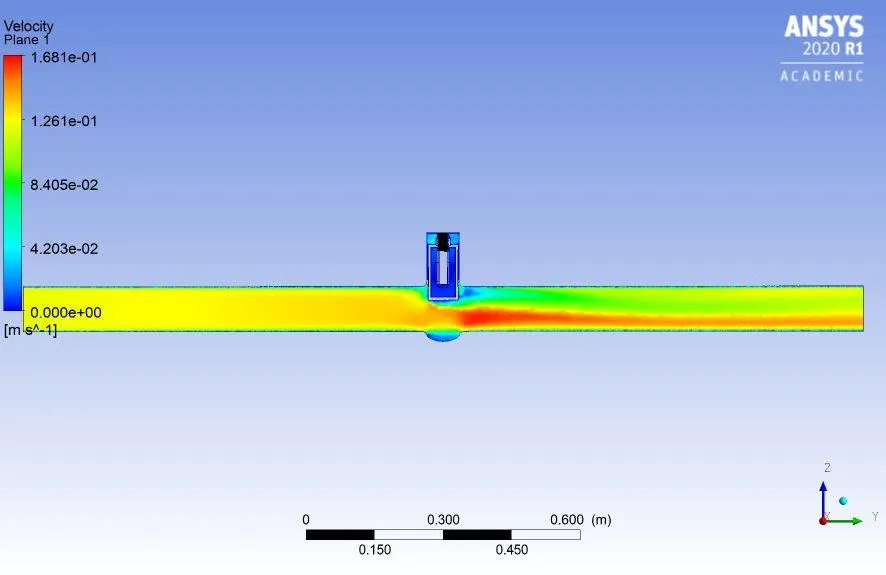
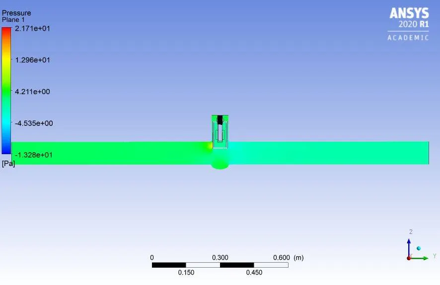
Contours and animation for pressure and velocity are created on the plane created.
RESULTS:-
GATE-VALVE OPENING:-10%
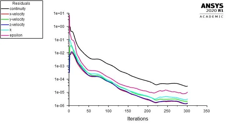
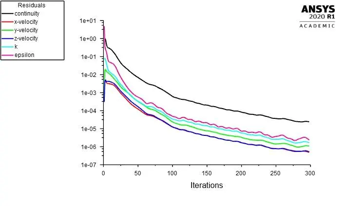
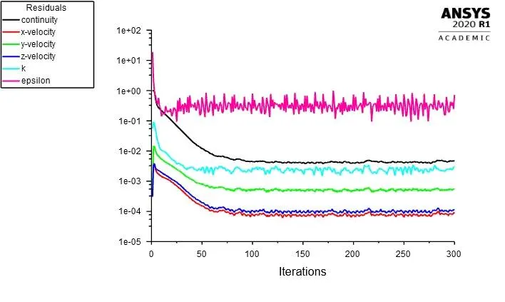
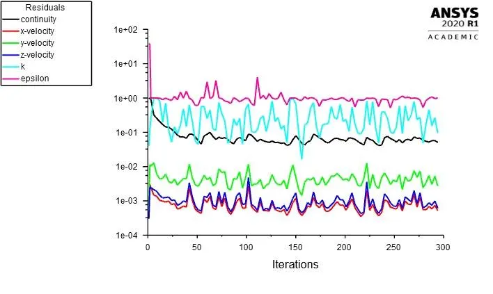
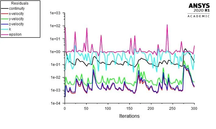
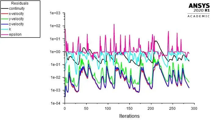
Residuals:-
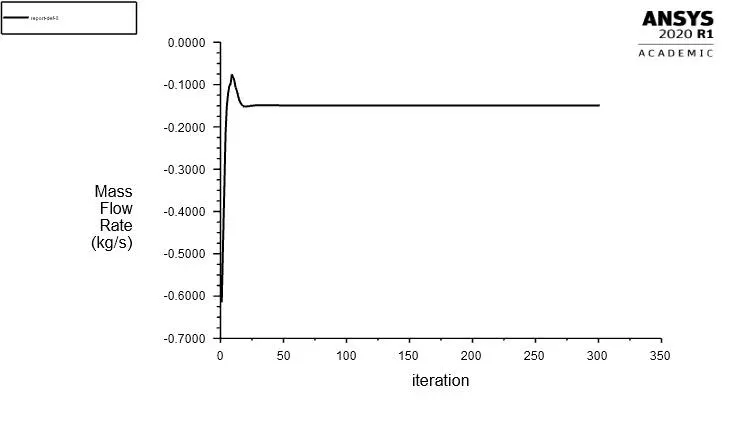
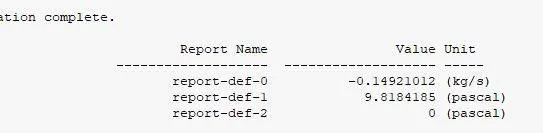
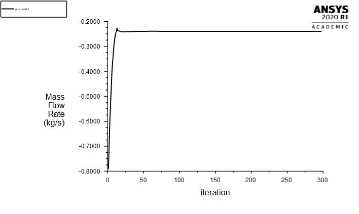
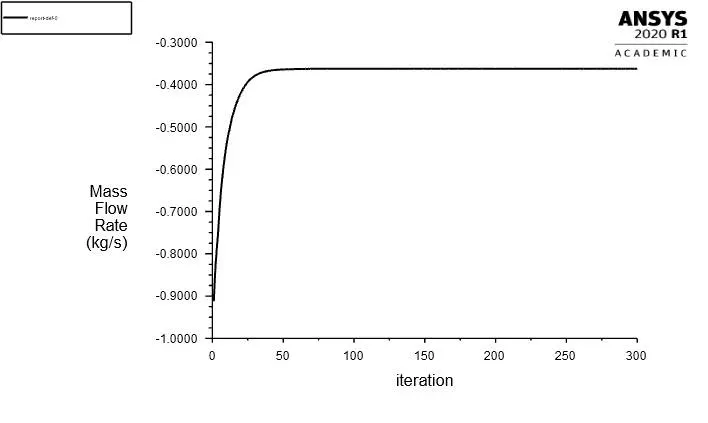
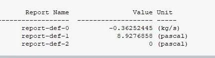
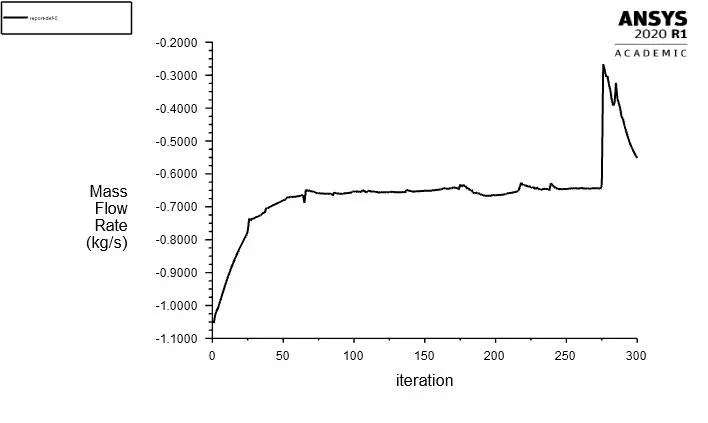
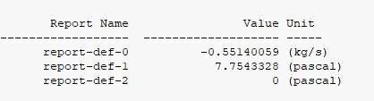
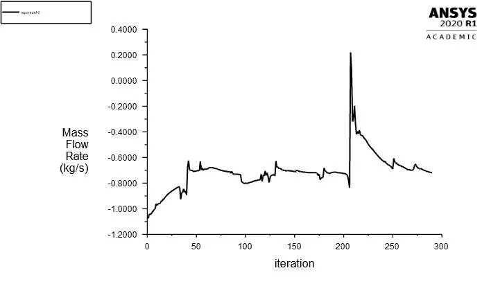
Mass flow rate:-
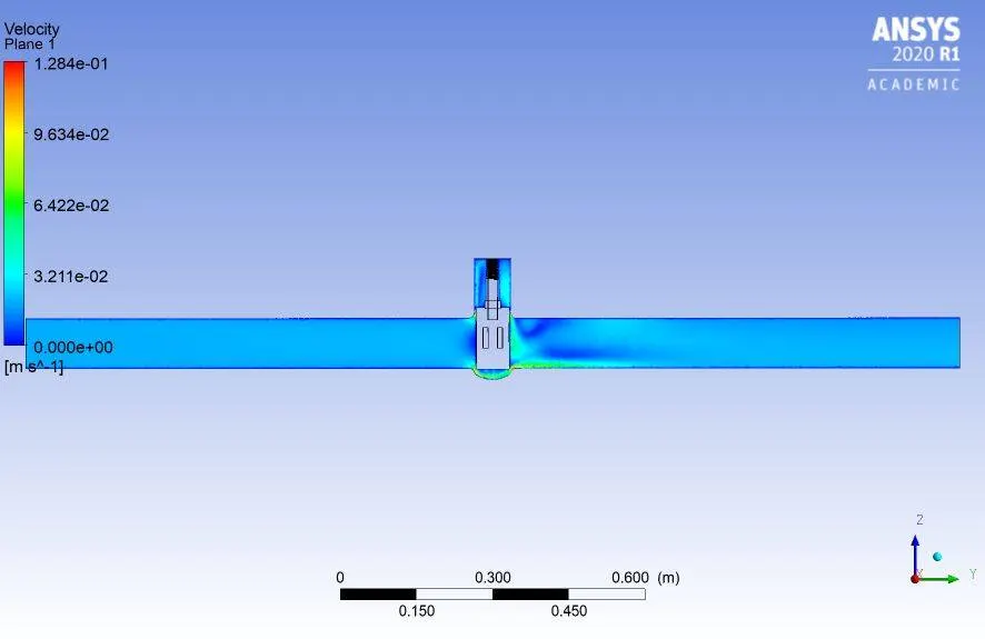
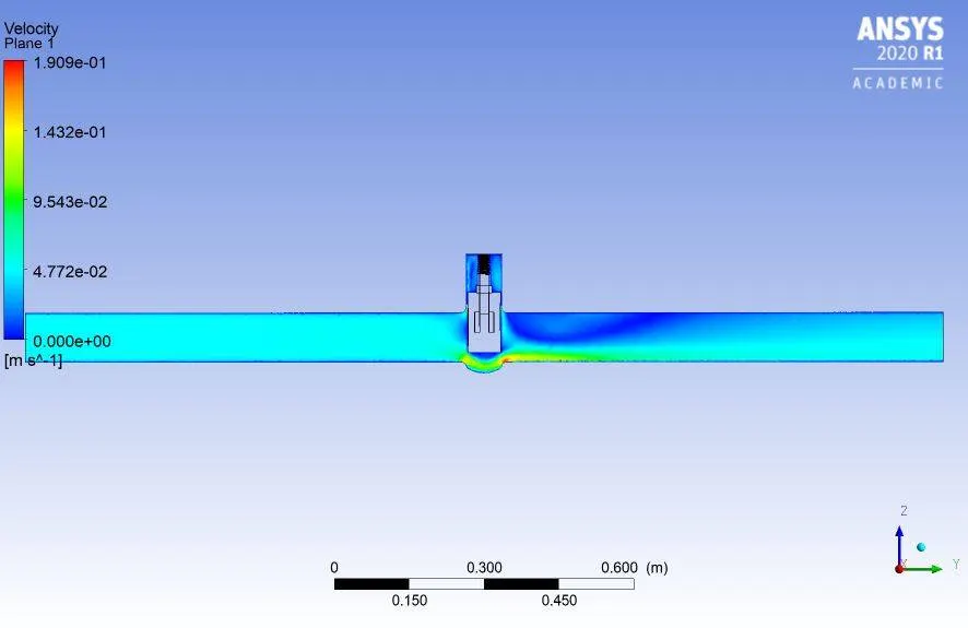
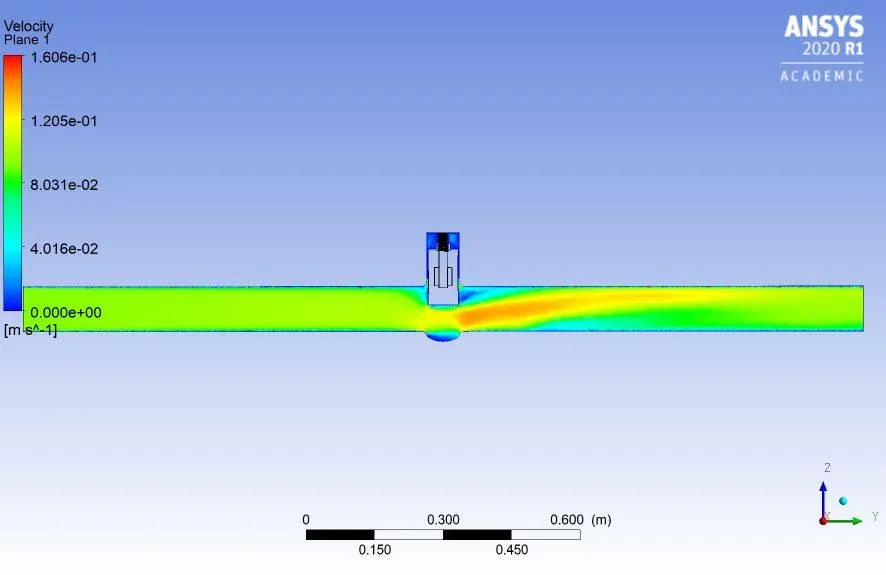
Velocity:-
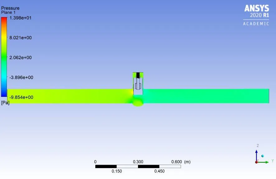
Pressure:-
GATE-VALVE OPENING:-20%
Residuals:-
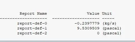
Mass flow rate:-
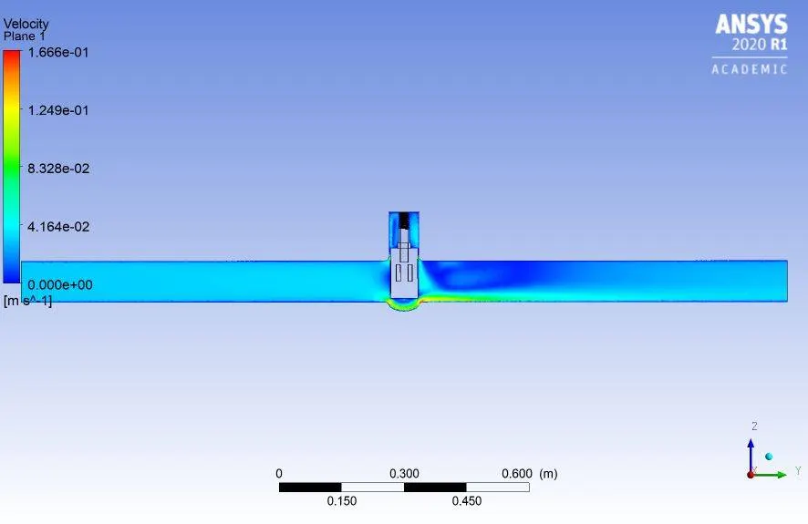
Velocity:-
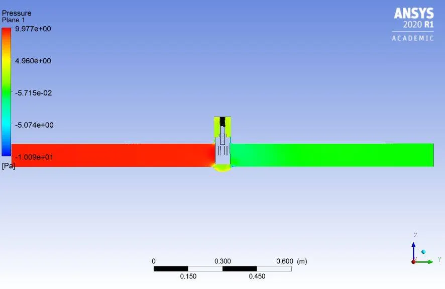
Pressure:-
GATE-VALVE OPENING:-30%
Residuals:-
Mass flow rate:-
Velocity:-
Pressure:-
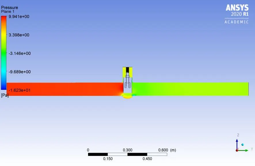
GATE-VALVE OPENING:-40%
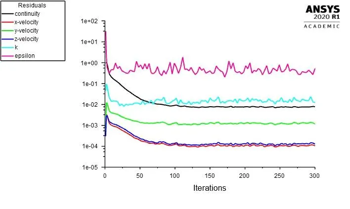
Residuals:-
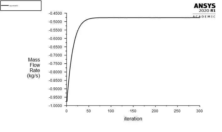
Mass flow rate:-

Velocity:-
Pressure:-
GATE-VALVE OPENING:-50%
Residuals:-
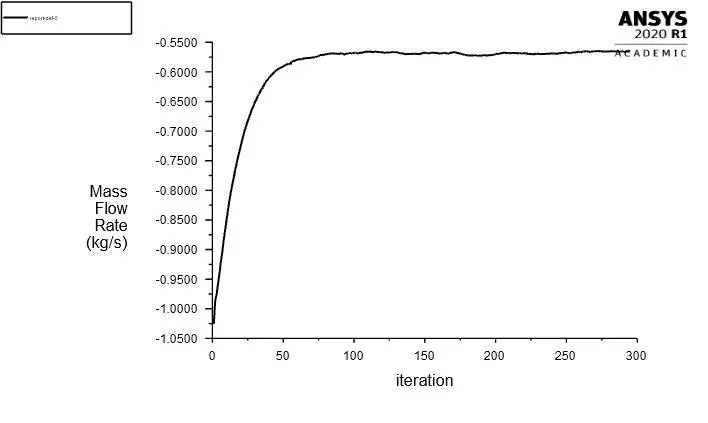
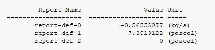
Mass flow rate:-
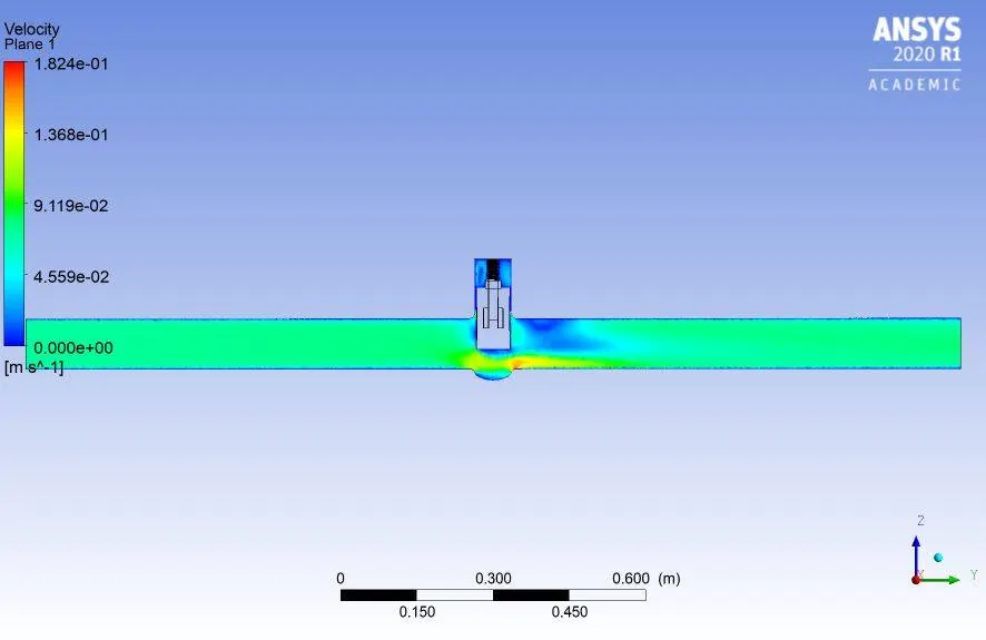
velocity:-
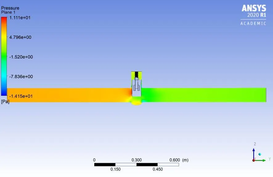
Pressure:-
GATE-VALVE OPENING:-60%
Residuals:-
Mass flow rate:-
Velocity:-
Pressure:-
GATE-VALVE OPENING:-70%
Residuals:-
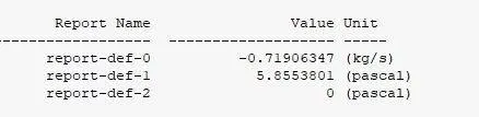
Mass flow rate:-
Velocity:-
Pressure:-
GATE-VALVE OPENING:-80%
Residuals:-
Mass flow rate:-
Velocity:-
Pressure:-
Now let's calculate the flow coefficient and flow factor
Flow coefficient:-
The flow coefficient of a device is a relative measure of ts efficiency at allowing fluid flow. It desicibe relationship between the pressure drop across an orifice valve or other assembly and te corresponding flow rate.
Mathematically,
`underset(v)(C)= Q*sqrt((SG)/(DeltaP))`
`underset(v)(C)`= Flow coefficient
Q- flow rate
SG= specific gravity
`DeltaP`= pressure drop
Flow Factor:-
Flow factor is the flow coefficient in metric units. It is defined as the flow rate in cubic meters per hour of water at a temperature of 16 degrees celsius with a pressure drop of 1 bar,
Mathematically,
`underset(v)(K)= Q*sqrt((SG)/(DeltaP))`
So the `underset(v)(K)`= 0.8658`underset(v)(C)`
Now let's continue to calculate the design points.
Sample calculation for explanation with 20% opening
Flow Coefficient:-
Q= 0.2393736 kg/s =0.2397*15.85 = 3.8 gal/min.
SG = 1 (for water)
`DeltaP`= Inlet pressure - outlet pressure =9.53 Pa = 9.7 * 0.000145 = 0.00138 psi
Now,
`underset(v)(C)`= `3.8*sqrt((1)/(0.00138))` = 102.25
Flow Factor:-
`underset(v)(K)=underset(v)(C) *0.865`
`underset(v)(K)`= 88.45
In the similar way we can calculate the other design points as well. mentioned in the tabular form.
| Design point (mm) | Inlet pressure (Pa) | Q (mass flow rate) Kg/s | `DeltaP`(Pa) |
Flow coefficient |
Flow factor |
| 10 | 10 | 0.1492101 | 9.18 | 62.66 | 54.20 |
| 20 | 10 | 0.2397779 | 9.53 | 102.25 | 88.45 |
| 30 | 10 | 0.3625244 | 8.92 | 159.80 | 138.22 |
| 40 | 10 | 0.4765741 | 8.14 | 219.78 | 190.10 |
| 50 | 10 | 0.5655507 | 7.39 | 273.90 | 236.92 |
| 60 | 10 | 0.5514005 | 7.75 | 257.97 | 223.14 |
| 70 | 10 | 0.7190634 | 5.85 | 392.95 | 339.90 |
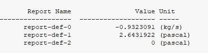
| 80 | 10 | 0.9323091 | 2,64 | 846.17 | 731.93 |
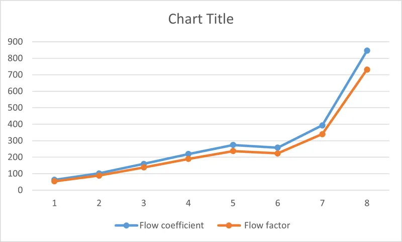
Graph:-
OBSERVATION AND CONCLUSION:-
- From the graph we can see that as we lift the gate valve both flow coefficient and flow factor are increasing.
- As we we increase the design point velocity and mass flow rate is also getting increased and pressure will is dropping through the orifice pipe.
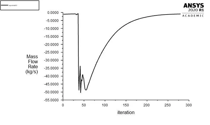
- We get a negative mass flow rate in the fluent as the flow is going out, fluent takes that as negative.
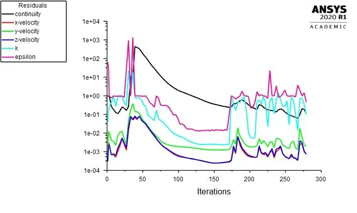
- Solution is converged as the value in residuals is going down to 0.0001
- Parametric study helps us to minimize the setting up time by directly changing the values in the parametric study.