Frequency analysis of a rotating shaft using Solidworks
AIM: To calculate the critical frequencies of a rotating shaft by performing frequency analysis
OBJECTIVE:
- To create a 3D model of a rotating shaft
- To calculate the critical frequencies of the shaft by performing frequency analysis
- To plot the 5 modal shapes of the shaft and identify resonant frequency of each cases
INTRODUCTION
Finite element analysis
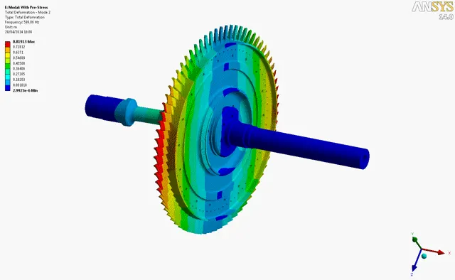
- Finite Element Analysis or FEA is the simulation of a physical phenomenon using a numerical mathematic technique referred to as the Finite Element Method, or FEM. This process is at the core of mechanical engineering, as well as a variety of other disciplines. It also is one of the key principles used in the development of simulation software. Engineers can use these FEM to reduce the number of physical prototypes and run virtual experiments to optimize their designs.
- Complex mathematics is required in order to understand the physical phenomena that occur all around us. These include things like fluid dynamics, wave propagation, and thermal analysis.
- Analyzing most of these phenomena can be done using partial differential equations, but in complex situations where multiple highly variable equations are needed, Finite Element Analysis is the leading mathematical technique.
Rotating shaft
- A shaft is a rotating machine element, usually circular in cross section, which is used to transmit power from one part to another, or from a machine which produces power to a machine which absorbs power.
- They are mainly classified into two types:
- Transmission shafts are used to transmit power between the source and the machine absorbing power; e.g. counter shafts and line shafts.
- Machine shafts are the integral part of the machine itself; e.g. crankshaft
Critical speed of shaft
- In solid mechanics, in the field of rotor-dynamics, the critical speed is the theoretical angular velocity that excites the natural frequency of a rotating object, such as a shaft, propeller, leadscrew, or gear. As the speed of rotation approaches the object's natural frequency, the object begins to resonate, which dramatically increases system vibration. The resulting resonance occurs regardless of orientation. When the rotational speed is equal to the numerical value of the natural vibration, then that speed is referred to as critical speed.
- All rotating shafts, even in the absence of external load, will deflect during rotation. The unbalanced mass of the rotating object causes deflection that will create resonant vibration at certain speeds, known as the critical speeds. The magnitude of deflection depends upon the following:
(a) Stiffness of the shaft and its support
(b) Total mass of shaft and attached parts
(c) Unbalance of the mass with respect to the axis of rotation
(d) Amount of damping in the system
In general, it is necessary to calculate the critical speed of a rotating shaft, such as a fan shaft, in order to avoid issues with noise and vibration. - Like vibrating strings and other elastic structures, shafts and beams can vibrate in different mode shapes, with corresponding natural frequencies. The first vibrational mode corresponds to the lowest natural frequency. Higher modes of vibration correspond to higher natural frequencies. Often when considering rotating shafts, only the first natural frequency is needed.
Critical speed depends upon the magnitude and location of the shaft unbalance, the length of the shaft, its diameter, and the kind of bearing support. Many practical applications suggest as good practice that the maximum operating speed should not exceed 75% of the critical speed; however, there are cases that require speeds above the critical speed to work correctly. In such cases, it is important to accelerate the shaft through the first natural frequency quickly so that large deflections don't develop.
Theory
- Resonant frequency: Resonant frequency is the oscillation of a system at its natural or unforced resonance. Resonance occurs when a system is able to store and easily transfer energy between different storage modes, such as Kinetic energy or Potential energy as you would find with a simple pendulum.
- Resonance :The increase in amplitude of oscillation of an electric or mechanical system exposed to a periodic force whose frequency is equal or very close to the natural undamped frequency of the system.
- Mode:The mode is a statistical term that refers to the most frequently occurring number found in a set of numbers. The mode is found by collecting and organizing data in order to count the frequency of each result. The result with the highest count of occurrences is the mode of the set, also referred to as the modal value.
- Mode Shapes:The deformed shape of the structure at a specific natural frequency of vibration is termed its normal mode of vibration. Some other terms used to describe the normal mode are mode shape, characteristic shape, and fundamental shape. Each mode shape is associated with a specific natural frequency.
- Modes are inherent properties of a structure, and are determined by the material properties (mass, damping, and stiffness), and boundary conditions of the structure. Each mode is defined by a natural (modal or resonant) frequency, modal damping, and a mode shape (i.e. the so-called “modal parameters”).
- Resonance :The increase in amplitude of oscillation of an electric or mechanical system exposed to a periodic force whose frequency is equal or very close to the natural undamped frequency of the system.
Procedure:
- Create a sketch of rotating shaft of desired dimensions and revolve it 360 degrees to obtain the solid model.
- Select a new study and choose frequency analysis.
- Select "Alloy Steel" as the material
- Apply the bearing fixtures and mesh the geometry
- Run the study to get different shapes and resonant frequency.
Material properties
Material: Alloy steel
3D model
Bearing fixtures
Meshing
RESULTS
Modal results
| MODE | PLOT |
| MODE 1 | |
| MODE 2 | |
| MODE 3 | |
| MODE 4 | |
| MODE 5 |
Resonant frequencies for each modal number
Conclusion
The frequency analysis is performed on the rotating shaft and the different mode shapes of the rotating shaft is been listed above. Thus the following are observed after viewing the results of the frequency analysis on the rotating shaft:
- In each modal case, if the the shaft achieves resonance, it can severly damage the shaft and its surrounding system.
- It is suggested to operate the rotating shaft such that it does not reach the above-mentioned frequencies to prevent the shaft from damage.
- By doing so, it reduces the damage to the shaft and hence it provides the increase in life period to the rotating shaft.
Hence, the frequency analysis is been performed to find out the different mode shapes of the shaft using the simulation add-in in SolidWorks.