Foundation Design using SAFE
Question 1. Model the isolated footing provided in week 11 challenge on SAFE. Analyze and design it to verify the size, depth and steel provided as per calculations.
AIM: To model the isolated footing which is provided to us in the previous challenge and to analyse and design it to verify the size,depth and steel which is provided according to the calculations. Below is the detailed step-by-step procedure to design the isolated Footing using the SAFE software.
PROCEDURE:
- In order to design the Isolated footing in the SAFE software,the first thing that we need to do is download the SAFE software from the CSI official account.
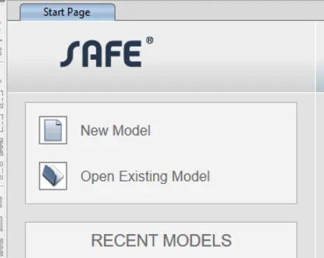
- After installing the software,open the SAFE software, click on the option NEW MODEL that is available at the start page of the SAFE software just as shown in the below given image:
- The SAFE software has almost similar interface as of the ETABS software interface. So it becomes little bit easy to work on the SAFE software as we are aware of some functions because of ETABS software.
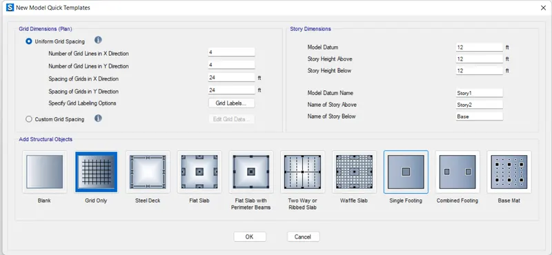
- Now after opening the New Model there will be a new dialouge box named as the New Model Quick Templates,in that template there is an option called single footing in Add Structural Objects options just click on that just as shown in the below given image:
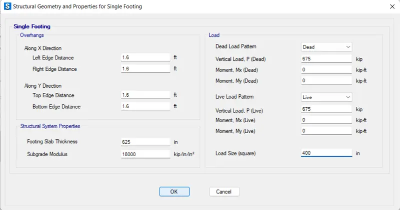
- After this there will be another dialouge box named as the Structural Geometry and Properties for Single Footing,in that dialouge box fill the data just as shown in the below given image:
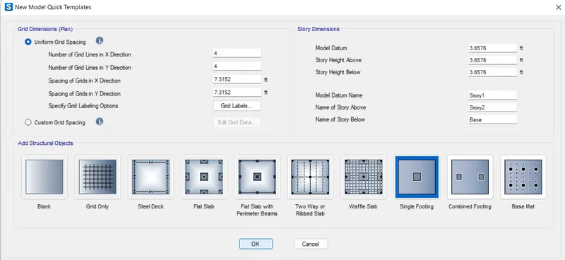
- After this fill the data in the New Model Quick Template just as shown in the below given image:
- After this we have to define the material properties as just we define the material properties for the ETABS software,similarly here also to define the material property just go to the define option then there will be a drop-down list and in that list there will be an option called Material Property just click on that option just as shown in the below given image:
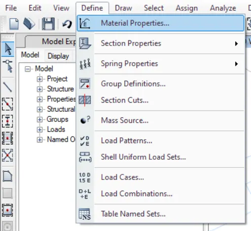
- Here in the foundation we don't need shear ties so we don't have to provide Fe415,so for designing the foundation we only need to define the concrete and Fe500 property.
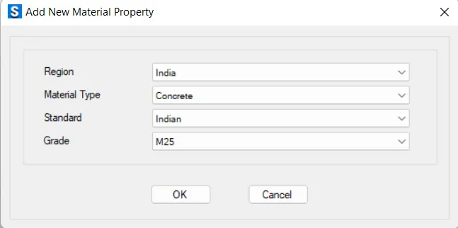
- So now first we will be defining the concrete property,so after clicking the material property there will be another dialouge box named as the Add New Material Property in that dialouge box fill the data just as shown in the below given image:
M25:
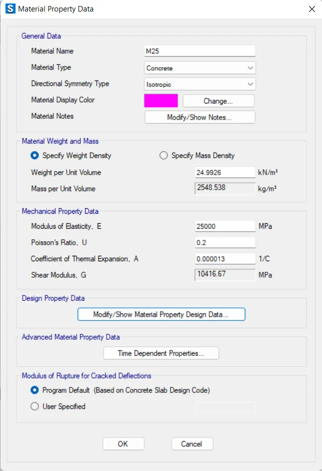
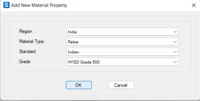
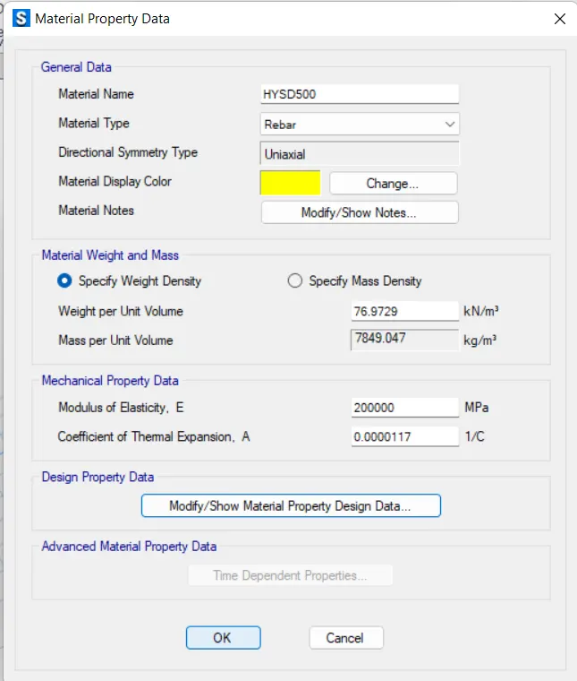
- Similarly do the same procedure for the Fe500:
Fe500:
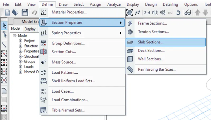
- After assigning the material properties now we will be going to assign the section properties,so in order to assign the section properties first we need to go to the Define option then there will be a drop-down list in that list there will be an option called Section Property click on that option after that another list appears on the screen in that list there is another option called Slab Section just click on that option as shown in the below given image:
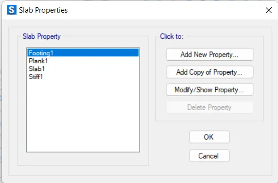
- After that there will be a dialouge box open named as Slab Properties,in that option there is an option Add New Property just click on that option just as shown in the below given image:
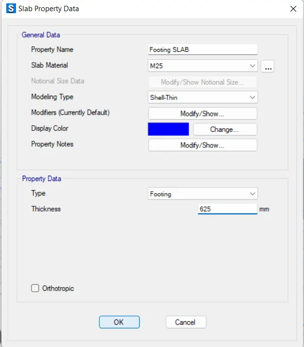
- Here for designing the footing we need to define only 2 different properties of slab,one is the footing slab and the other one is the stiff slab for the column area over the footing.
- But the depth of both types of slabs remains the same as calculated from the pressure formula.
- And select the Property type as Footing for the footing slab and Stiff for the stiff slab just as shown in the below given image:
FOOTING SLAB:
STIFF SLAB:
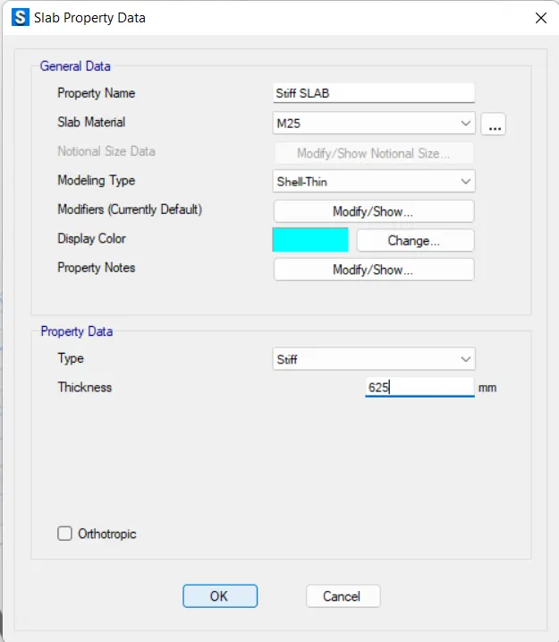
- After assigning the slab properties now we will be defining the Load combinations.
- So in order to define the load cominations we need to define two types of loads here. One load is Service Load and the other load is Ultimate Load.
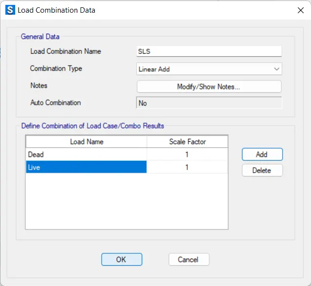
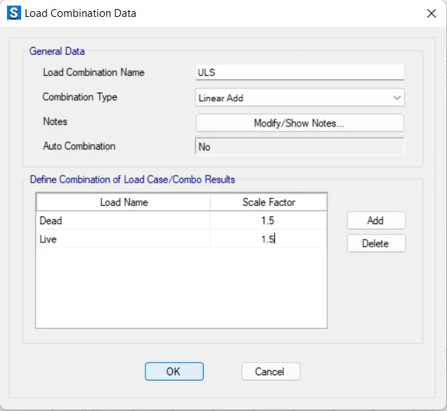
- In the service load combinations we will be considering the total unfactored column load,and in case of the ultimate load combinations we will be considering factored load,which means a factor of 1.5 is to be multiplied by the dead and the live load.
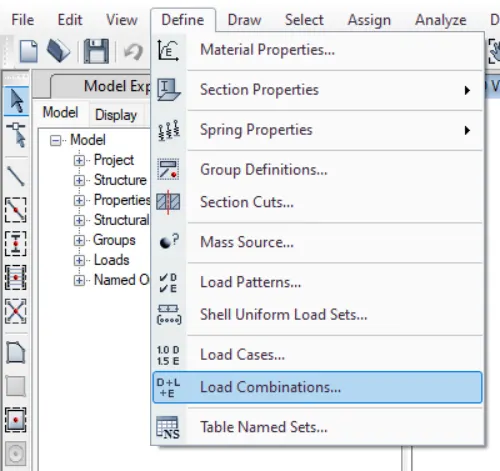
- So, in order to apply the load combinations first we need to go to the option Define tab then there will be a drop-down list in that list there is an option called Load Combinations just as we used to do in the ETABS software as shown in the below given image:
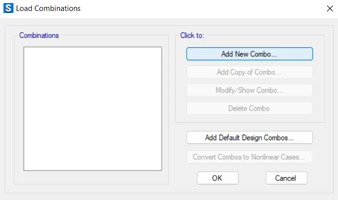
- After this there will be a dialouge box named as Load Combinations,and in that dialouge box there will be an option called Add New Combo just click on that option just as shown in the below given image:
- After that there will be another dialouge box named as the Load Combination Data just as shown in the below given image:
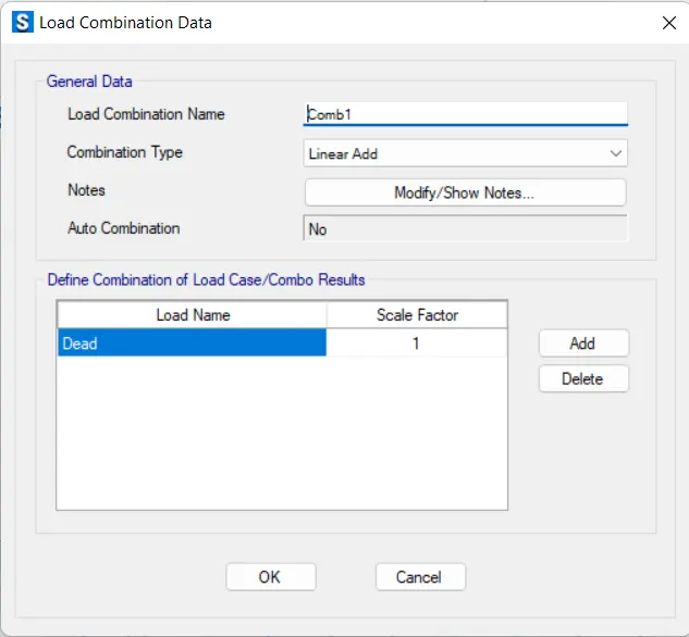
Serviceability Limits State (SLS) Load Combinations:
Ulitimate Limit State (ULS) Load Combinations:
- We have already assign the loads while defining the material property.
- But still we need to check whether the loads have been assigned or not.
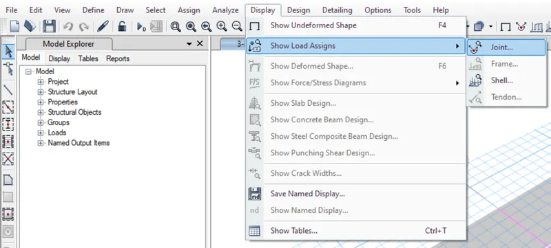
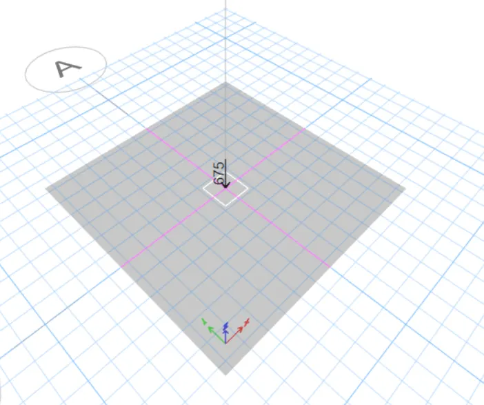
- So in order to check the assigned load or not,we need to go to the option Display click on that option after that there will be a drop-down list in that list there will be an option called Show Loads assigned just click on that option after that there will be another list in that there is an option called Joint just click on that option just as shown in the below given image:
- After this there will be another dialouge box named as Show Joint Loads,in that dialouge box we can check the loads that we have applied or not.
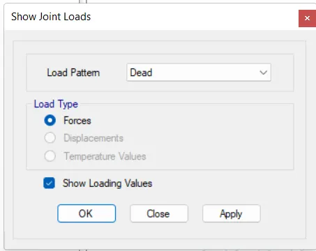
DEAD LOAD:
LIVE LOAD:

- That means the loads have been already assigned to the footing at the very begining of the project.
- So now the loads have been assigned now we will be assigning the Soil Spring property.
- And the value of the spring constant can be calculated by using the given formula:
Factor of Safety X Soil Bearing Capacity/Allowable settlement.
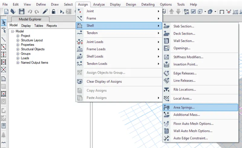
- Now in order to define and assign the soil spring property first we need select the footing and then go to the option Assign then there will be a drop-down list and in that list there will be an option called Shell just click on that option then there will be another list and in that list there will be an option called Area Spring just click on that option just as shown in the below given image:
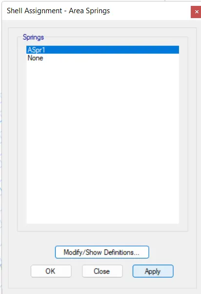
- After this there will be a dialouge box named as Shell Assignment-Area Spring,in that dialouge box select option Spring 1 and the click OK just as shown in the below given image:
AREA SPRING:
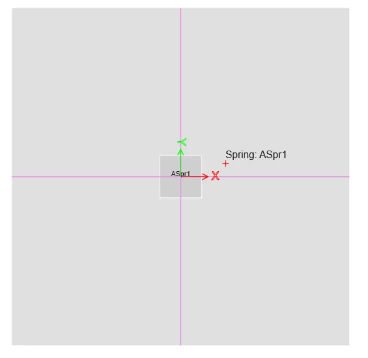
- After assigning the other properties now our model is set to run for the analysis.
- So in order to run the analysis just press the Run icon or press F5.
- But after the Run Analysis we need to check the few checks after finishing the run analysis.
- So the analysis have been completed as shown in the below given image:
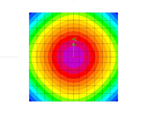
- Now there are few checks that we have to make,so first of all we need to check for the Settlement.
CHECK FOR SETTLEMENT:
- So the first thing we need to check is the total footing slab settlement measured in mm.
- And in order to check that first we need to go to the option Display then there will be a drop-down list in that list there will be an option called Show Deformed shape click on that option just as shown in the below given image:
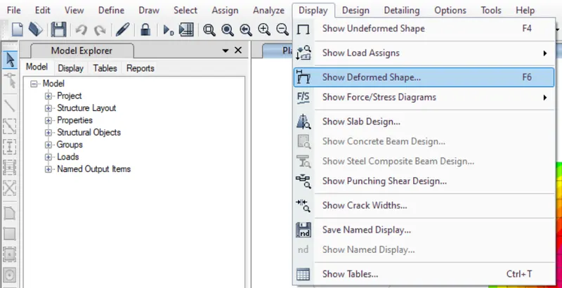
- After this there will be another dialouge box in that dialouge box select load combo as SLS.
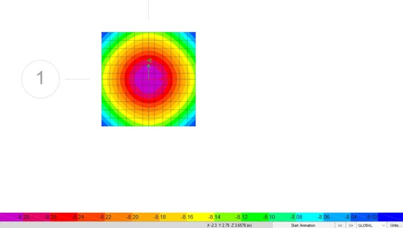
- And after that the SAFE software will show the total displacement in mm due to the load combinations.
- But the displacement should be within the limit according to the codes 25 mm is the maximum displacement allowed.
- So here as we can see the displacement in our case is way lesser than the said limit. Hence OK, as we can see in the below given image:
- So the next thing that we need to check is the Soil Pressure.
SOIL PRESSURE:
- So here we need to check the soil pressure due to the service load is with in the limit range of SBC or not.
- So in order to check the soil pressure first we need to go to the Display option then there will be a drop-down list in that list there will be an option called Show Force/Stress Diagram just click on that option and then there will be another list in that list there is an option called Soil Pressure just click on that just as shown in the below given image:
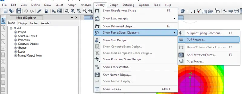
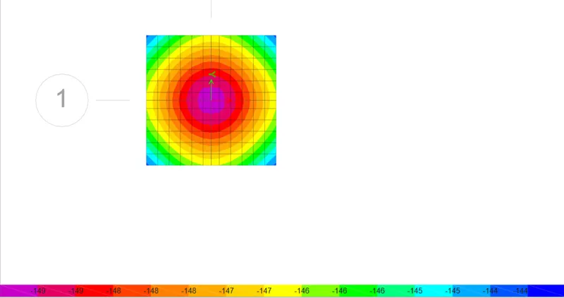
- So according to the codebook the soil pressuure must be less than the 150 KN/sq.m and in our case it is 149 KN/sq.m. Hence OK just as shown in the below given image:
- And now we will be checking for the Punching Shear.
PUNCHING SHEAR:
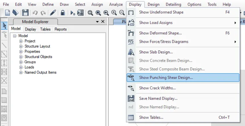
- In order to check the punching shear just go to the option Display then there will be a drop-down list in that list there will be an option called Show Punching Shear Design just click on that opion just as shown in the below given image:
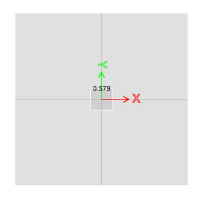
- So according to the codebook the punching shear should be less than 1, and in our case it is 0.579. Hence OK just as shown in the below given image:
- And now we will be checking for the longitudinal reinforcement requirement.
LONGITUDINAL REINFORCEMENT REQUIREMENT:
- As the model has passed all the checks successfully so far,now we have to look for the reinforcement requirement.
- Now we need to add the design strips in our model.
- So we can add the design strip automatically just go to the option Edit then there will be an option Add/Edit Support Lines just click on that option in that list and then there will be another option called Add Support Lines just click on that option and the stips in both the directions have been added.
Question 2. A column of size 600x600 carrying an unfactored gravity load (DL+LL) of 1175 KN is to be supported on pile cap, which ultimately transfers load to the piles underneath. Piles of 16 metres length and 500 mm diameter are to be used. Each pile has a load carrying capacity of 200 KN. Model, analyse and design the pile cap on SAFE to evaluate the following:
- Pile group to be used
- Depth of pile cap
- Longitudinal steel on top and bottom face in both directions
AIM: To model,analyse and design the pile Cap on the SAFE software
to evaluate the following:
- Pile group to be used
- Depth of pile cap
- Longitudinal steel on top and bottom face in both directions.
GIVEN DATA:
Column size : 600X600 sq.m.
Unfactored Gravity load (DL+LL) : 1175 KN.
Length of the Pile that is to be used : 16 m.
Diameter of one pile : 500 mm.
Pile Bearing Capacity : 200 KN.
CALCULATIONS:
(A) Number of piles:
- In order to calculate the number of piles we have a formula:
Total load/Bearing capacity of single pile.
Now we have total load of 1175 KN
and Bearing capacity of single pile is 200 KN.
Now we have to multiply the total load with the value of 1.1 as this is the multiplier for the soil surcharge pressure.
Therefore Number of Piles = `frac{1175xx1.1}{200}`
Number of Piles = 6.46 = 8 numbers.
So the number of piles = 8 Piles.
(B) Spring Constant:
We can calculate the spring constant by the given expression:
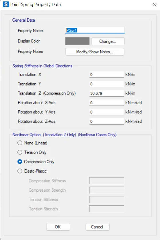
Point spring for the piles = AE/L
where A = Area = `frac{pi}{4}xxd^2`
E = 25000 N/sq.mm.
L = Pile Length = 16000 mm.
Spring Constant = EA/L.
Spring Constant = `frac{25000xx196349}{16000}`
Spring Constant = 306796.15 N/mm
(C) Length of the Pile:
- So according the IS code the minimum distance between two piles is 2.5Xdiameter of pile.
So the minimum distance between two pile here is 2.5 X 500 = 1250 mm.
As the diameter of pile is given as 500 mm.
But for the safe designing we adopted 1300 mm.
Now the distance from the edge of the footing to the edge of the pile = 1X diameter of pile
= 1 X 500
= 500 mm
- So based on the above calculations and the number of piles,the size of the footing is 4.1 X 4.1 sq.m.
- So below is the step-by-step procedure for the designing of the footing using the SAFE software.
PROCEDURE:
- So in order to model the footing,first step is to open the SAFE software and then open a new model and that option is available on the Start Page of the software.
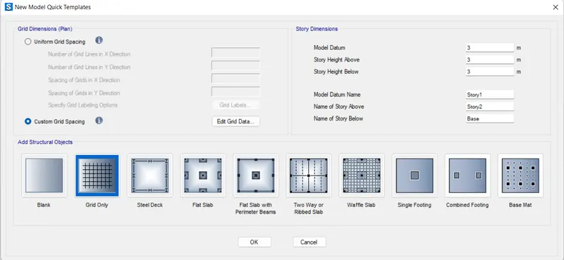
- After opening the New Model, instead of using the quick templates that are provided in the SAFE software already,use the option Custom grid spacing as we can see in the below given image:
- After that there will be another dialouge box named as the Set View Option and in that dialouge box edit the grid spacing in the X and Y direction just as shown in the below given image:
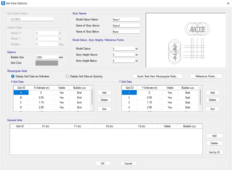
- After defining the grid spacing according to the calculation we had done before, now we will be defining the material and the section properties.
- And to define the material properties as just we define the material properties for the ETABS software,similarly here also to define the material property just go to the define option then there will be a drop-down list and in that list there will be an option called Material Property just click on that option just as shown in the below given image:
- Here in the foundation we don't need shear ties so we don't have to provide Fe415,so for designing the foundation we only need to define the concrete and Fe500 property.
- So now first we will be defining the concrete property,so after clicking the material property there will be another dialouge box named as the Add New Material Property in that dialouge box fill the data just as shown in the below given image:
M25:
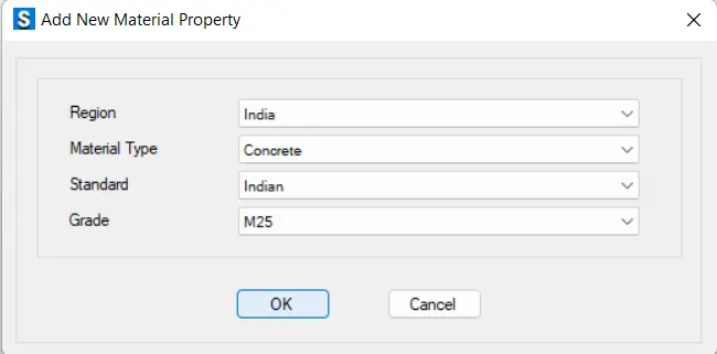
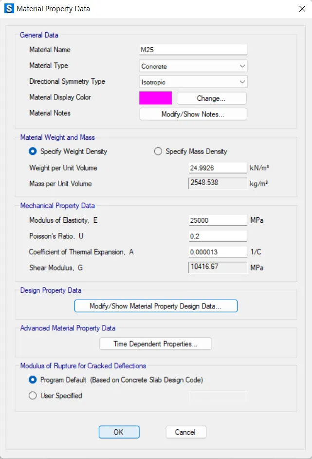
- Similarly do the same procedure for the Fe500:
Fe500:
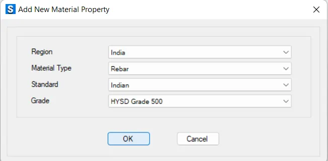
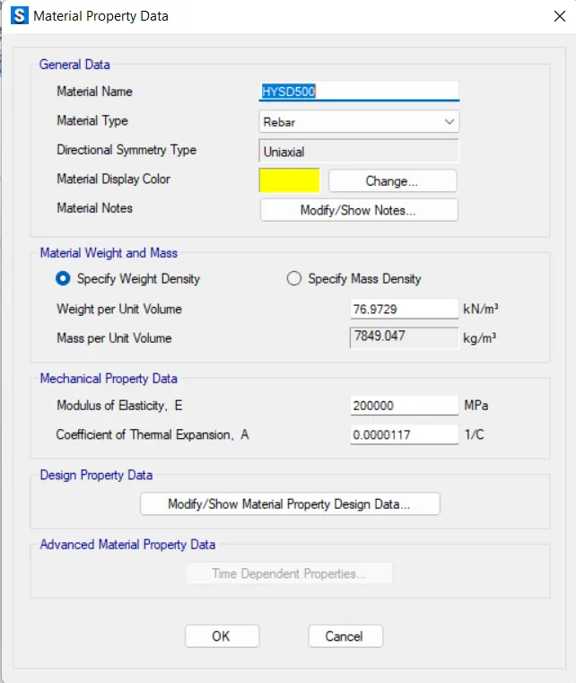
- After assigning the material properties now we will be going to assign the section properties,so in order to assign the section properties first we need to go to the Define option then there will be a drop-down list in that list there will be an option called Section Property click on that option after that another list appears on the screen in that list there is another option called Slab Section just click on that option as shown in the below given image:
- After that there will be a dialouge box open named as Slab Properties,in that option there is an option Add New Property just click on that option just as shown in the below given image:
- Here for designing the footing we need to define only 2 different properties of slab,one is the footing slab and the other one is the stiff slab for the column area over the footing.
- But the depth of both types of slabs remains the same as calculated from the pressure formula.
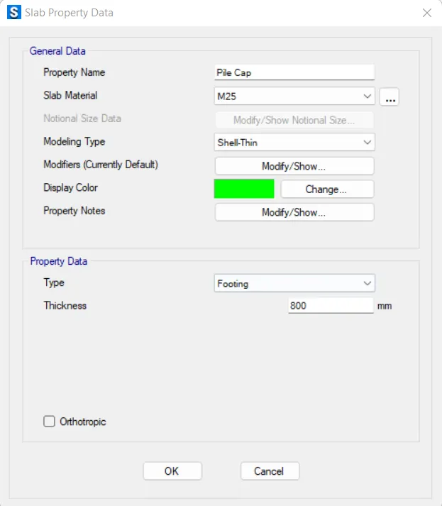
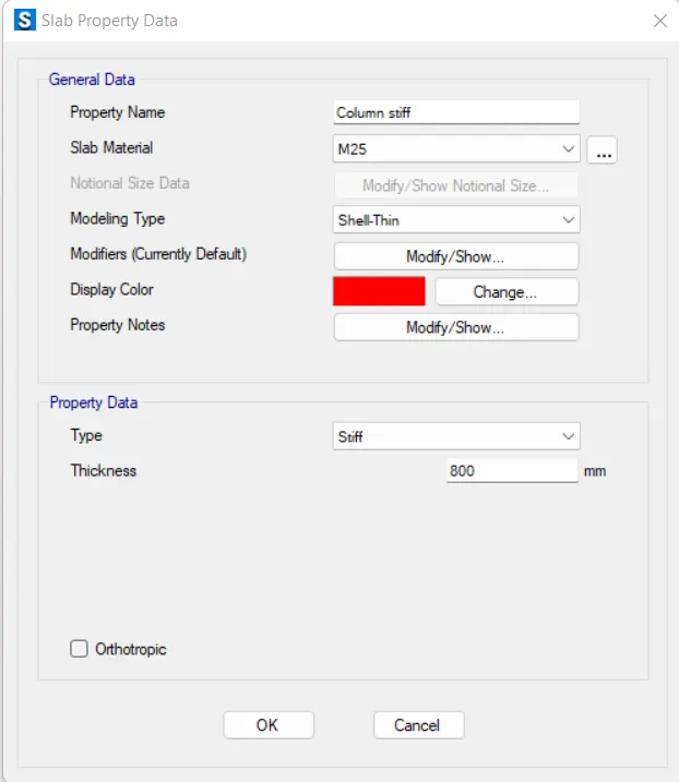
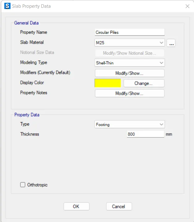
- And select the Property type as Footing for the footing slab and Stiff for the stiff slab just as shown in the below given image:
PILE CAP:
COLUMN STIFF:
CIRCULAR PILES:
- And now after assigning the material and the section properties now we will be drawing the pile section.
- In order to draw the pile cap first we need to draw the rectangular slab on the footing and in order to do that go to the option quick draw slab,and choose option Pile cap from the optios and draw the pile cap just as shown in the below given image:
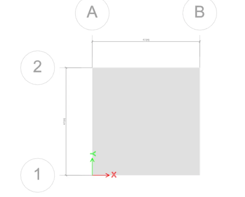
- After drawing the pile cap now we need to draw the piles and according to the calculations that we had done before we need to draw 8 number of piles.
- But before drawing the piles first we need to draw the points which will act as the centre for those circular piles.
- So in order to draw the points we need to go to the option Draw menu then there will be an option called
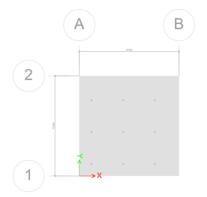
- After that draw the circular piles and to do that we need to go to the option quick draw area around point and then draw the circular pile using the point as the reference just as shown in the below given figure:
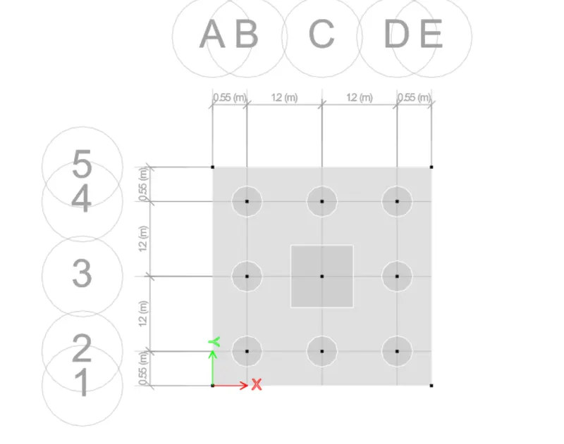
- And now we need to define and assign the point spring,
- So in order to assign the point spring just go to the option Assign click on that option then there will be drop-down list and in that list there will be an option called Joint click on that option and after that there will be another list in that list there will be another option called Springs click on that option just as shown in the below given image:
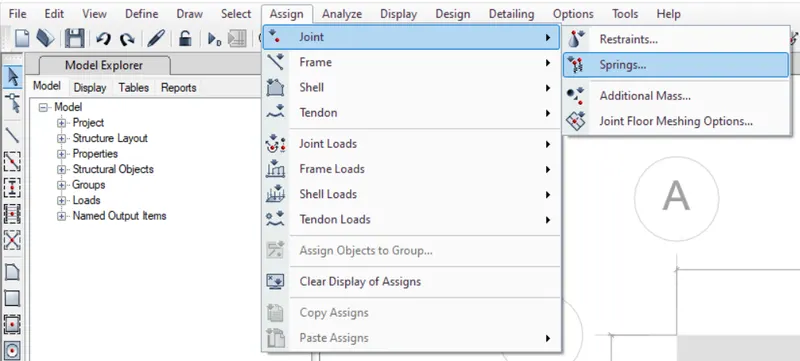
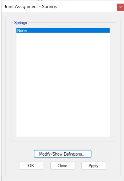
- After this there will be another dialouge box named as the Joint Assignment - Springs,in that box there is an option called Modify/Show Definitions click on that option just as shown in the below given image:
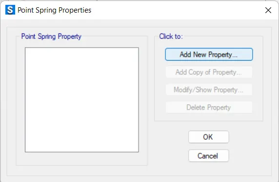
- After this there will be another dialouge box named as the Point Spring Properties and in that dialouge box there is another option called Add New Property just click on that option just as shown in the below image:
- After this there will be another dialouge box named as Point Spring Property Data and in that dialouge box fill the data just as shown in the below given image:
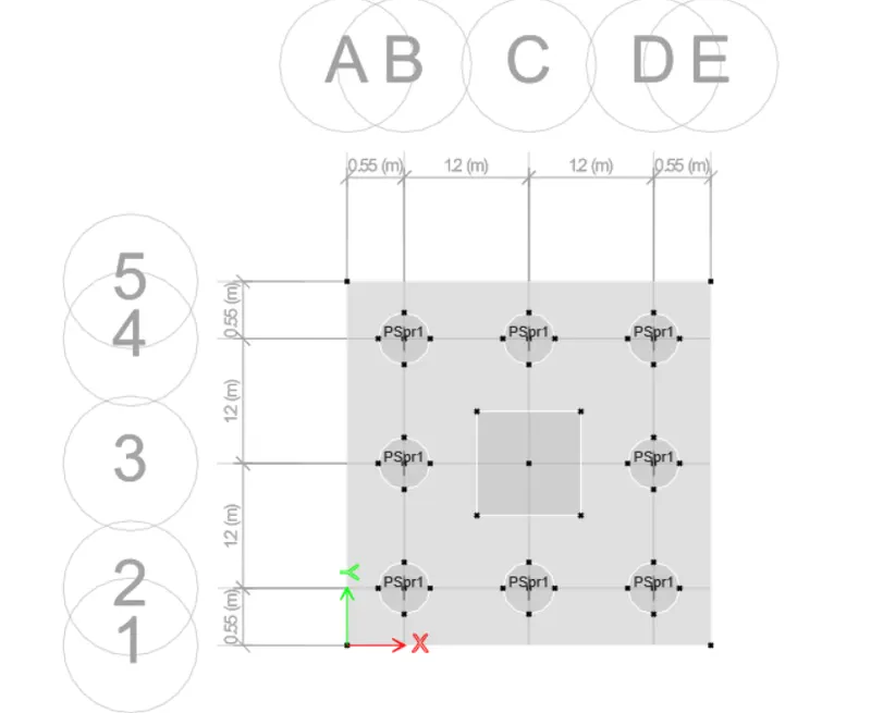
- And now Apply that point spring property just as shown in the below given image:
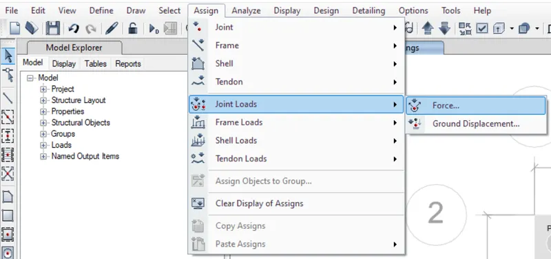
- After this we will be assigning the loads to the foundation and in order to asisn the loads first we need to go to the Assign menu and in that menu there will be a drop-down list and in that list there will be an option called Joint loads just click on that option after that there will be another option Force click on that option just as shown in the below given image:
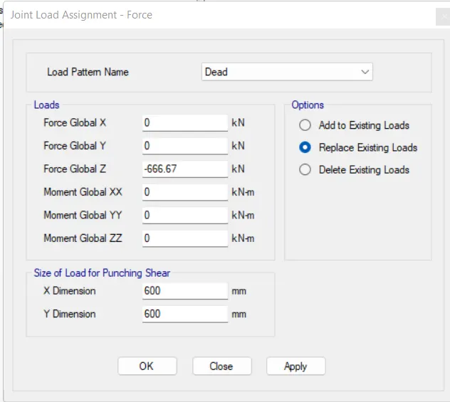
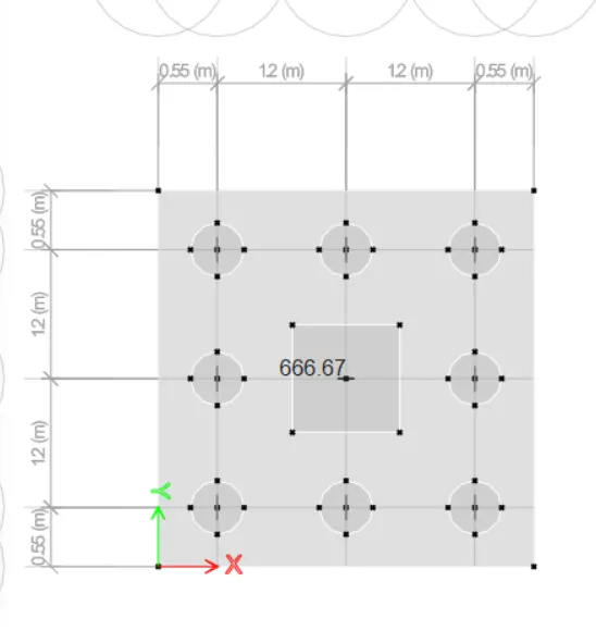
- And after that there will be another dialouge box named as the Joint Load Assignment - Force, in that dialouge box fill the details just as shown in the below given image:
DEAD LOAD:
LIVE LOAD:
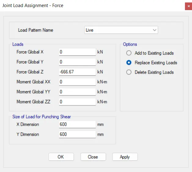
-After assigning the live load and the dead loads now we will be assigning the Load Combinations.
- So in order to define the load cominations we need to define two types of loads here. One load is Service Load and the other load is Ultimate Load.
- In the service load combinations we will be considering the total unfactored column load,and in case of the ultimate load combinations we will be considering factored load.
- So, in order to apply the load combinations first we need to go to the option Define tab then there will be a drop-down list in that list there is an option called Load Combinations just as we used to do in the ETABS software as shown in the below given image:
- After this there will be a dialouge box named as Load Combinations,and in that dialouge box there will be an option called Add New Combo just click on that option just as shown in the below given image:
- After that there will be another dialouge box named as the Load Combination Data just as shown in the below given image:
Serviceability Limits State (SLS) Load Combinations:
Ulitimate Limit State (ULS) Load Combinations:
- And now we have to assign the design strips also.
- In order to add the design strip we need to go to the Edit option after that there will be a drop-down list and in that list there will be an option called Add/Edit Design Strips just click on that option after that there will be another option called Add design strips using grids click on that option just as shown in the below given image:
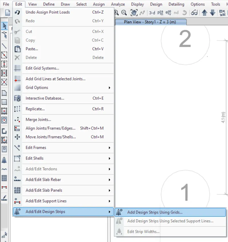
- After that there will be another dialouge box named as Add Design Strips Along Grid Lines, fill the details just as shown in the below given image:
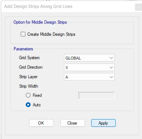
DESIGN STRIPS ALONG X-A:
- After assigning the other properties now our model is set to run for the analysis.
- So in order to run the analysis just press the Run icon or press F5.
- But after the Run Analysis we need to check the few checks after finishing the run analysis.
- So the analysis have been completed as shown in the below given image:
- Now there are few checks that we have to make,so first of all we need to check for the Settlement.
CHECK FOR SETTLEMENT:
- So the first thing we need to check is the total footing slab settlement measured in mm.
- And in order to check that first we need to go to the option Display then there will be a drop-down list in that list there will be an option called Show Deformed shape click on that option just as shown in the below given image:
- After this there will be another dialouge box in that dialouge box select load combo as SLS.
- And after that the SAFE software will show the total displacement in mm due to the load combinations.
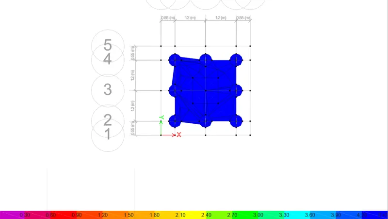
- But the displacement should be within the limit according to the codes 25 mm is the maximum displacement allowed.
- So here as we can see the displacement in our case is way lesser than the said limit. Hence OK, as we can see in the below given image:
- And now we will be checking for the Punching Shear.
PUNCHING SHEAR:
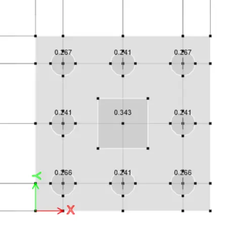
- In order to check the punching shear just go to the option Display then there will be a drop-down list in that list there will be an option called Show Punching Shear Design just click on that opion just as shown in the below given image:
- So according to the codebook the punching shear should be less than 1, and in our case it is 0.579. Hence OK just as shown in the below given image:
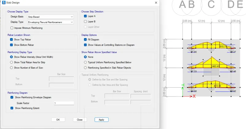
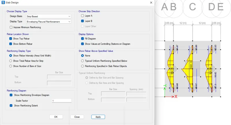
LONGITUDINAL REINFORCEMENT REQUIREMENT:
- As the model has passed all the checks successfully so far,now we have to look for the reinforcement requirement.
- Now we need to add the design strips in our model.
- So we can add the design strip automatically just go to the option Edit then there will be an option Add/Edit Support Lines just click on that option in that list and then there will be another option called Add Support Lines just click on that option and the stips in both the directions have been added.
LAYER A:
LAYER B:
RESULT:
- Completed the design of Pile cap foundation and isolated footing using the SAFE software.