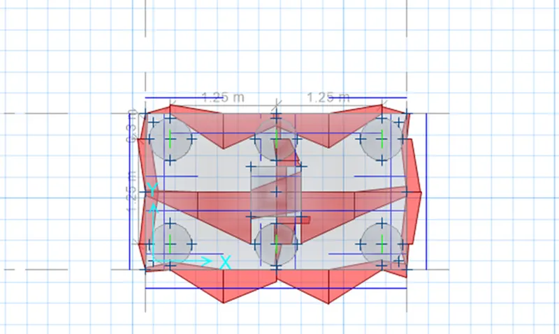
Foundation Design using SAFE
- FOUNDATION DESIGN USING SAFE
-
Aim - i) To model the isolated footing provided in week 11 challenge on SAFE.
ii) To Analyze and design it to verify the size, depth and steel provided as per calculations.
iii) To model the pile cap on SAFE software .
Introduction -
1) CSI SAFE (Slab Analysis by the Finite Element Method) is the best tool for designing concrete slabs and foundations.
2) SAFE provide easiness to engineer towards the safe design of structures with powerful tools like draw, analyze, design and detailing etc.
3) Laying out models is quick and efficient way with the user-friendly drawing tools, or user can import \
model layouts from AutoCAD or loading conditions from other software’s like CSI ETABS and CSI SAP2000.
Procedure -
Step 1)
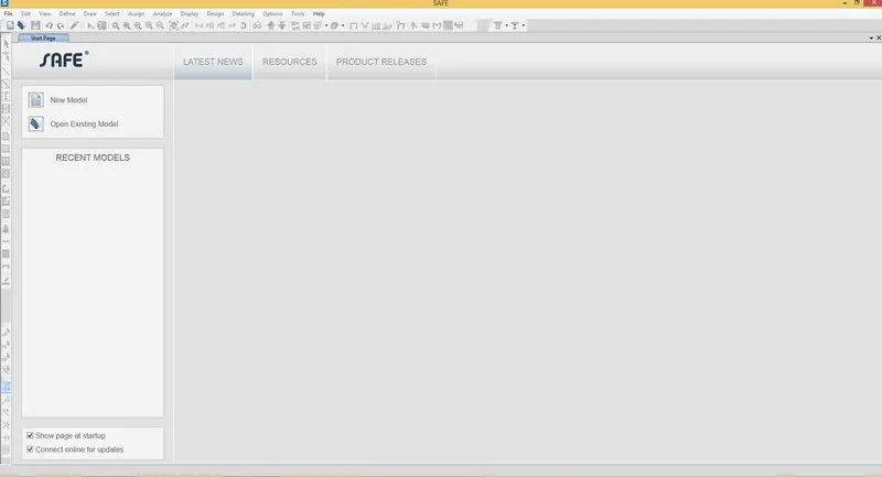
i) Open the SAFE 2020 Software .
ii) Click on New Model
Step 2)
i) Once you click on New model
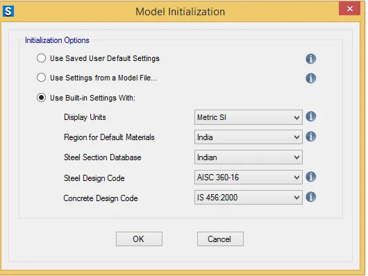
ii) A following Dialog box will open .
iii) Display Units- Metric SI
iv) Select the Region Indian
v) Select the Concrete Design Code - IS 456-200
vi) Click on Okay
Step 3)
i) Once you click Okay
ii) Model Quick Template box will open
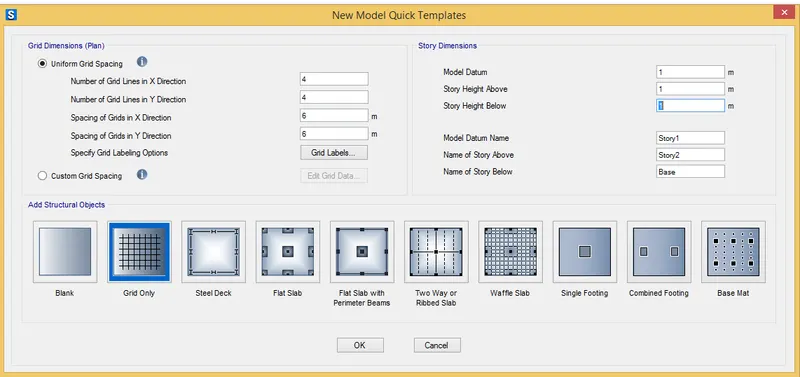
iii) Click on Single Footing - As we are designing Isolated Footing .
Step 4)
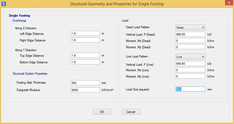
i) Enter the dimension as per calculation we have done in Week 11 challenge .
ii) As we have got Footing Size = 3.8m x 3.8m
iii) Enter the Direction Along X and Y direction as = 1.9 m
iv) Footing Slab Thicknes = 800 mm
v) For Modulus Subgrade =
we know the formula ,
Modulus of Subgrade = `(FOS X SBC )/ ( Allowab l e Set tl ement )`
i) Assume FOS = 3 as per IS 13290
ii) SBC = 150 given
iii) Allowable Settlement ( For Isolated footing ) = 0.025 m ( AS per Is 1904 )
= `(3 X 150 )/0.025`
= 9000 `(Kn )/(m^3)`
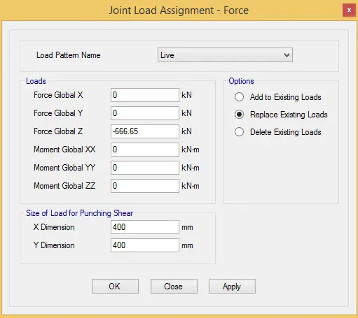
vi) Now we have to add the Load
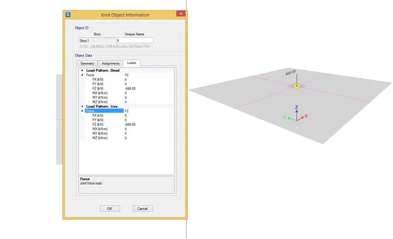
i) For Dead load and Live load -
= (Total Unfactored load ) / 2
= `(1333.3 / 2)`
= 666.65 Kn
vi) Load Size = In that we have to enter Column Size = 400 mm
vii) Once you enter all the details Click in Okay
Step 5)
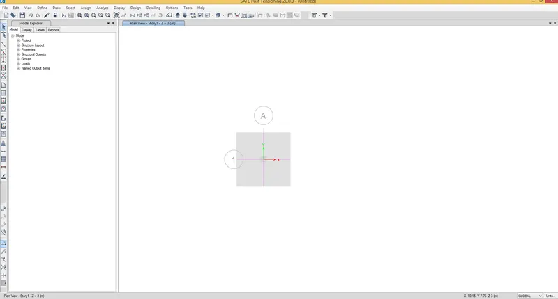
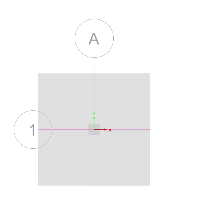
i) Once you click okay
ii) You will see the geometry is created in Model space as follows
Step 6)
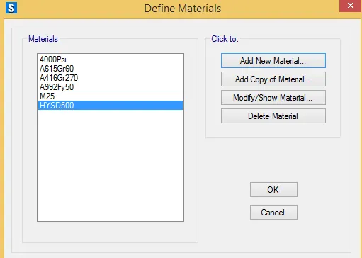
i) Now we have to add Material Properties
ii) Click on Define - Material Properties
ii) Click on Add new materials
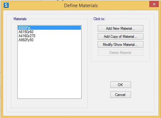
iii) Once you click Add new material add the following parameters
iv Material Type - Concrete
v) Grade - M25
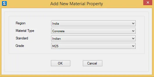
vi) Click on okay .
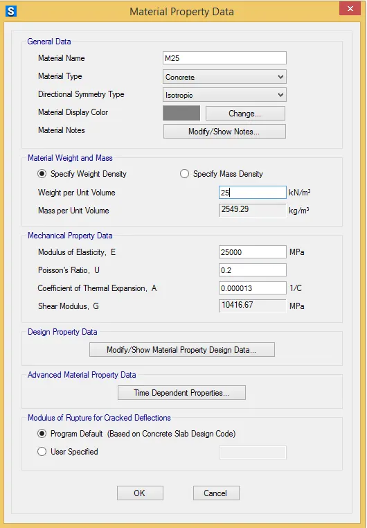
vii) Simialarly add the Rebar Properties .
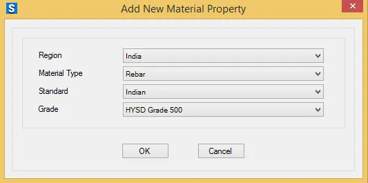
viii) Click on Okay
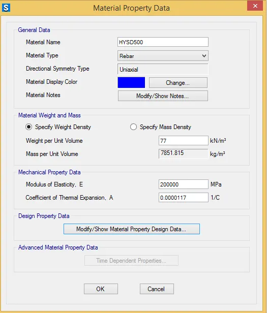
ix) Properties has been Define
Step 7)
i) Now we have to define Slab properties
ii) As we already define slab properties in Grid Section
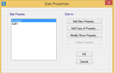
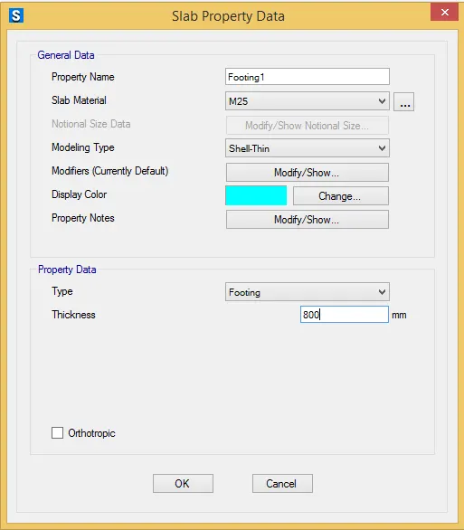
iii) Clic on Modify properties - Add
iv Select the Slab Material - M25
v) Assign tje thickness = 800 mm
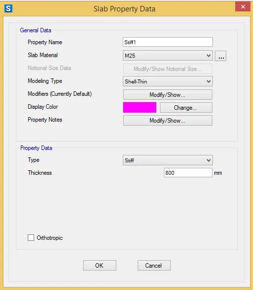
vi) Similarly Modify the Stiff slab
Step 8)
i) Now we have to assign Soil Properties
ii) Define - Soil Properties
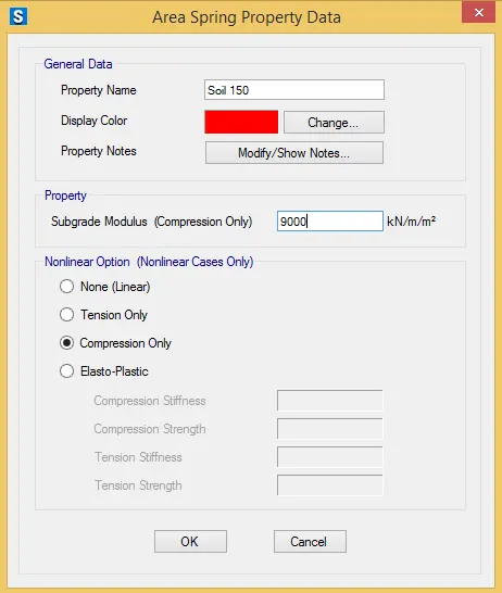
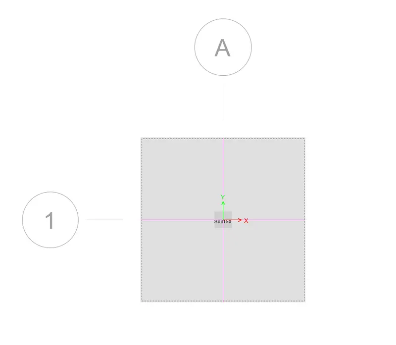
iii) Right Click on slab you will see the Soil Properties has been assigned
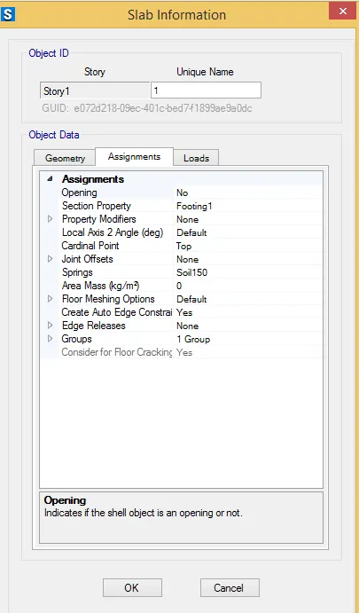
Step 9)
i) Now we have to check if loads are defined are not .
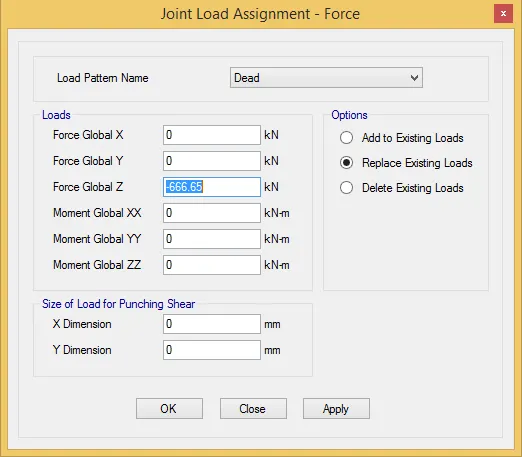
Step 10)
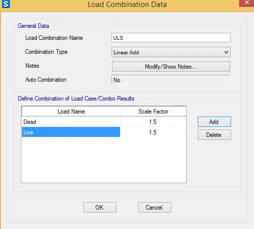
i) Now we have to define the Load Combinations
ii) For that Define - Load Combinations - Either you can Add New combo or you can Add default Combo
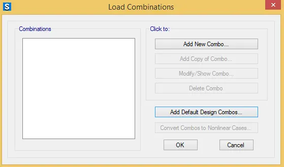
iii) Will Add new Combo as follows
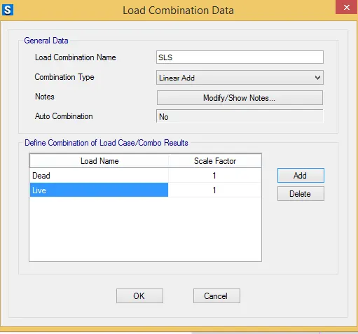
Step 11)
i) Now we can Run the model
ii) Click on Run Analysis
iii) Save the File
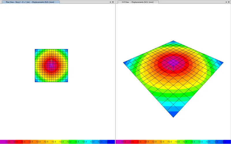
iv) Now you will see the Displacements
v) Click On Defotmed Shape - Select Combination as - SLS and see the displacement
vi) As displacement is -12 mm which is less than 25 mm ............Safe
2) Check for Bearing Pressure
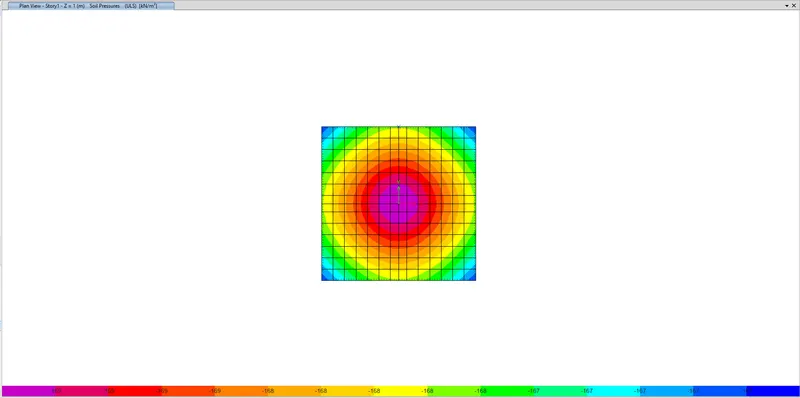
i) For that Click On Display - Soil Pressure - Select Combination as - ULS
ii) As we can see that Bearing pressure is more than SBC
i.e 169.22kn/m2 > 150 kN/m2 ..........................Unsafe
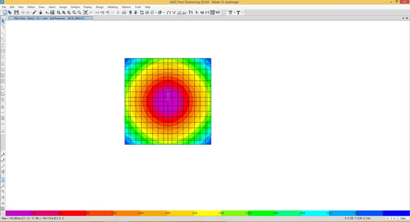
iii) We have to Increase the area to see if we can reduce the bearing pressure below the SBC
iv) Now provide the area as 4m x 4m
v) Here we can see that after increasing the area Bearing pressure is reduced
i.e -143.30 < 150 Kn/m2..............................Safe
3) Check of Punching Shear
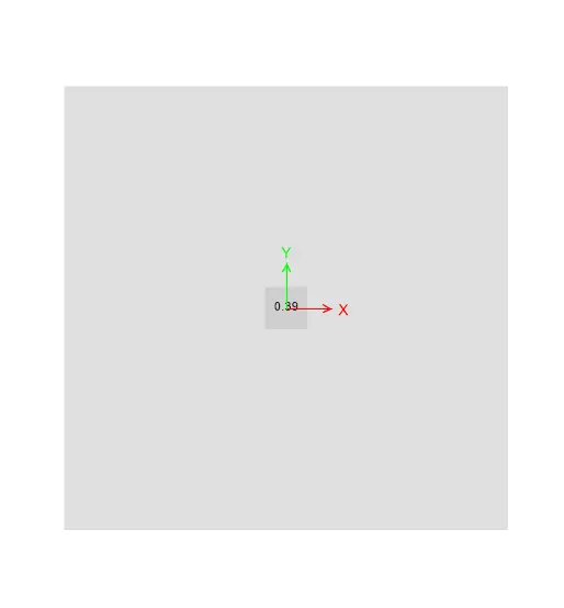
i) Click on Display - Punching Shear
ii) As we can see that Punching shear is less than 1
i.e 0.39 <1.....................................Safe
Step 12)
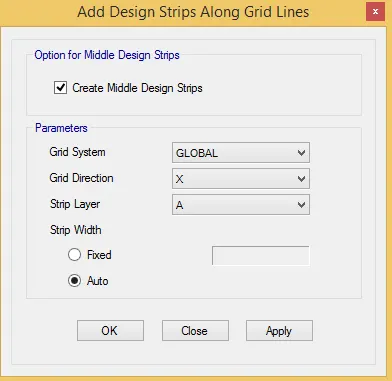
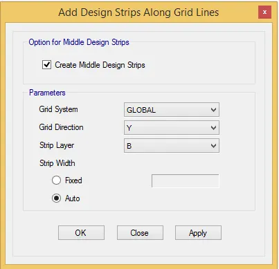
i) Now we have to add the Design srips
ii) Click on Edit - Add / Edit Design Strips
iii) Add the Strips in both X and Y direction
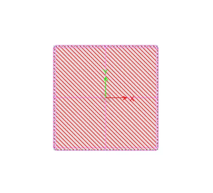
iv) Strips has assigned
v) Command Cntrl + W to see the set display option
vi) In that tick on Strip widtht to see the Strip width
Step 13
i) Now again Run the model
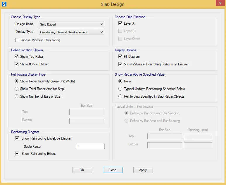
ii) Click on Slab Design
iii) Select Layer A
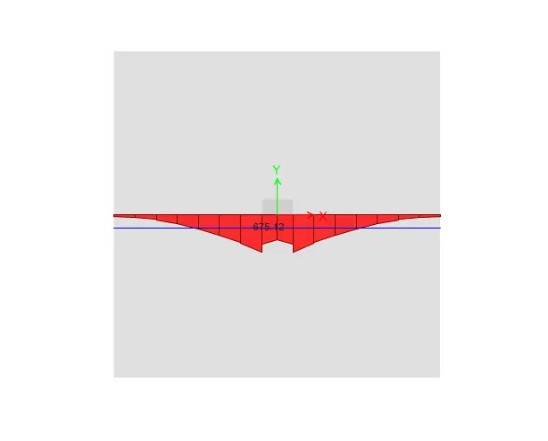
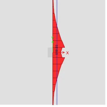
iv) Similarly Select layer B
Results -
i) Isolated Footing is Designed for Square column of size 400mm x 400 mm
ii) We have to Provide Footing Size as 4m x 4m
iii) Bearing soil pressure is checked and found to be safe
iv) Punching shear ratio is check and found to be safe
Q.2)
Aim - To Model, analyse and design the pile cap on SAFE
Procedure -
Step 1) Given data -
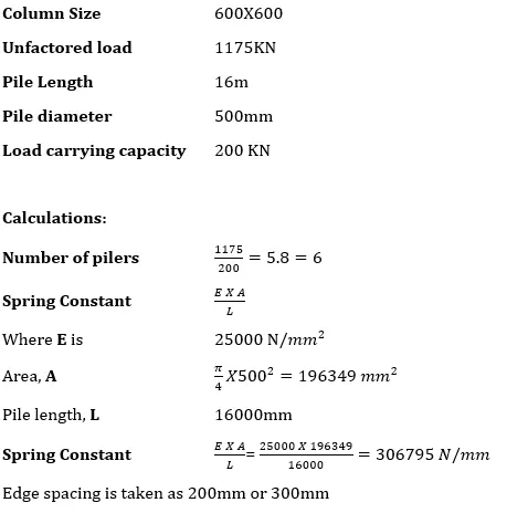
i) As per IS 2911 (part 2) the spacing between the piles is taken as 2.5 times the diameter of pile
ii) The edge spacing we have assume it as 300 mm .
Step 2)
i) Open the SAFE 2020 Software .
ii) Click on New Model
Step 3)
i) Once you click on New model
ii) A following Dialog box will open .
iii) Display Units- Metric SI
iv) Select the Region Indian
v) Select the Concrete Design Code - IS 456-200
vi) Click on Okay
Step 4)
i) Once you click Okay
ii) Model Quick Template box will open
iii) Click on grid only
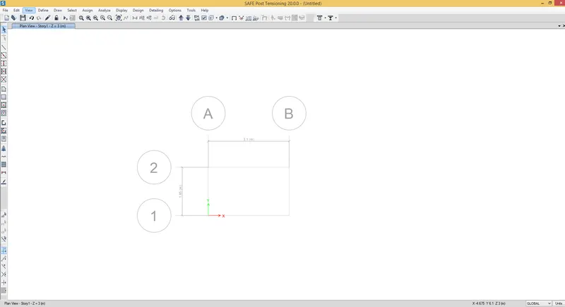
iv) Enter No of grids in X and Y = 2
v) Enter spacing in X = 3.1 m
vi) Enter Spacing in Y = 1.85 m
Step 5)
i) Now we have to assign the Material proprties
ii) Define - Material Properties
i) Click on Add new materials
iii) Once you click Add new material add the following parameters
iv Material Type - Concrete
v) Grade - M25
vi) Click on okay .
vii) Simialarly add the Rebar Properties .
viii) Click on Okay
ix) Properties has been Define
Step 6)
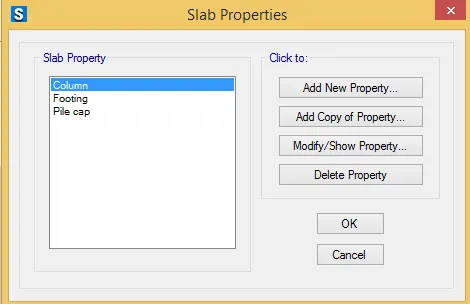
i) Now we have to define Slab properties
ii) In pile cap we have to define 3 slabs properties
iii) Footing
iv) For Column
v) For Pile cap
Step 7)
i) Once slab proerties are defined
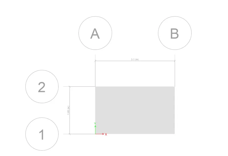
ii) Now we have to start the modeling
iii) Select Quick draw slab options
iv) Draw the slab select Footing as property
Step 8)
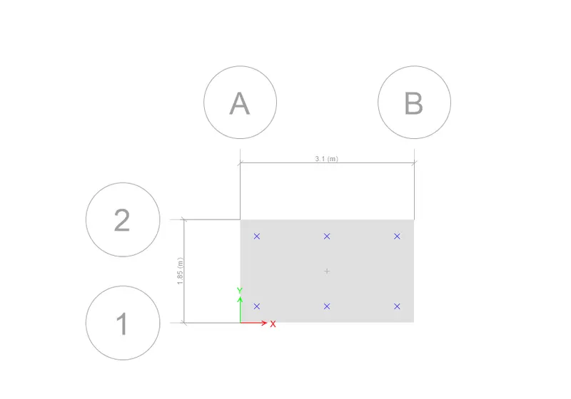
i) Now we have to mark the position of Pile cap
ii) For that we have to add the points
iii) Draw - Draw reference points
Step9)
i) Now we have to add column slab
ii) Click on Quick draw area / points
iii) Select the property
iv) and draw the columns
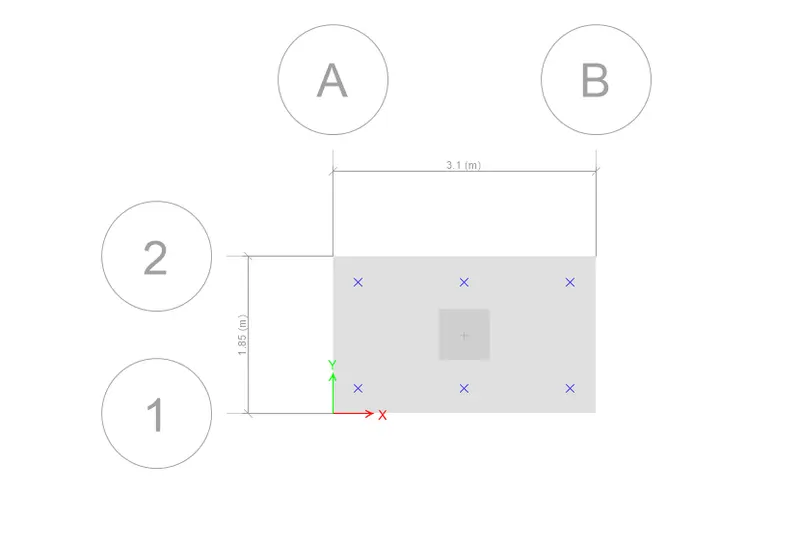
v) Similarly draw the pile caps
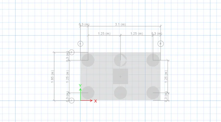
Step 10)
i) Now we have to add Springs to the pile because it behaves like a spring
ii) Click on Assign – Support Data – point springs
iii) Spring Constant from above calculation is taken as
iv) Add Spring Constant - 306795 Kn/m
v) Select - Compression Only
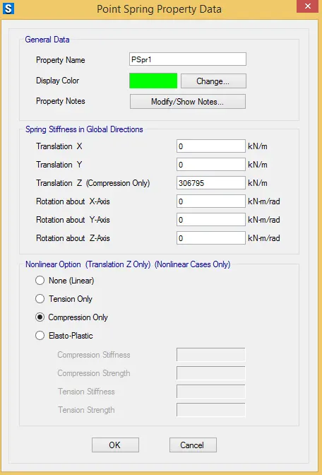
vi) Click on Okay
vii) Spring Constant has been assigned .
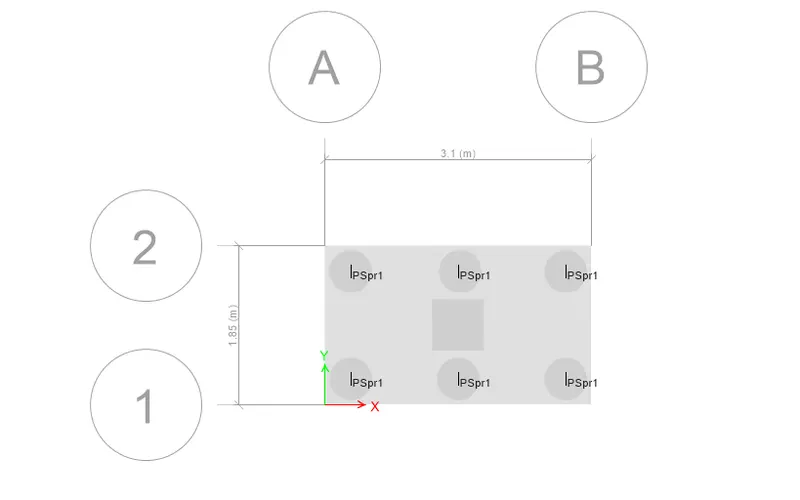
Step 11)
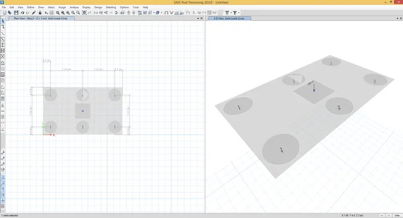
i) Now we have to add the loads
ii) Go to Assign - Joint loads - point force
iii) Assign 587.5 Kn dead load and 587.5 Kn live load
Step 12)
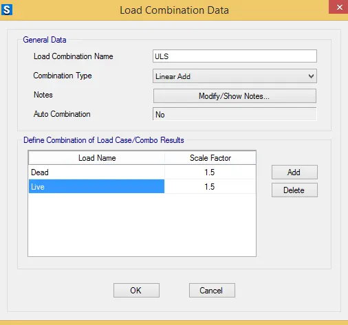
i) Now we have to add load combinations
ii) Define - Load combination
iii) Define the load combination as follows
Step 13)
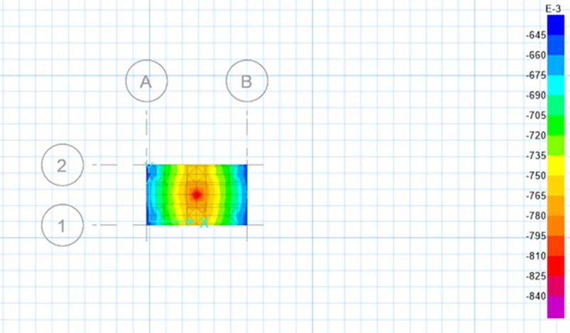
i) Now Run the model
ii) Click on Run Analysis
iii) We found that Displacement is less than allowable settlement
i.e 0.8 < 25mm
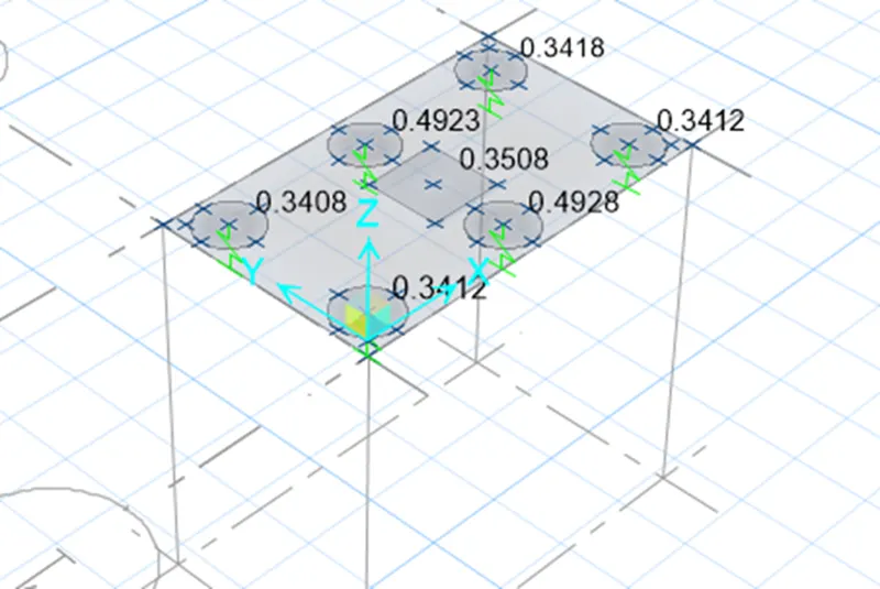
2) Check for Punching Shear -
i) Click on Display - Punching Shear
ii) As we can see that Punching shear is less than 1
i.e 0.49 <1.....................................Safe
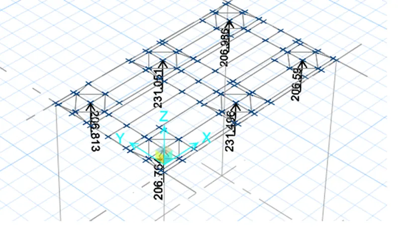
3) Joint Reaction
i) As all the reaction forces are according to the limit, Its safe
Step 14)
i) Now we have to add the Design srips
ii) Click on Edit - Add / Edit Design Strips
iii) Add the Strips in both X and Y direction
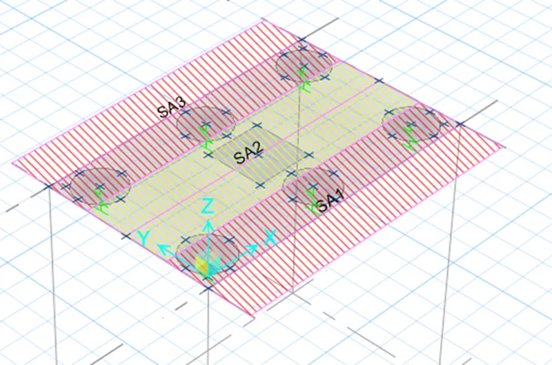
iv) Strips has assigned
v) Command Cntrl + W to see the set display option
vi) In that tick on Strip widtht to see the Strip width
Step 13)
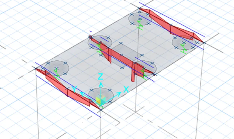
i) Run the model
ii) Click on slab design
iii) Select the layer A to see the reinforcement
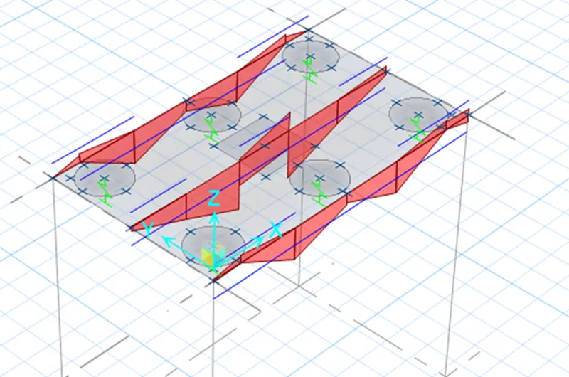
iii) Similarly in Layer B
Results -
i) Pile Cap is Designed for Square column of size 600mm x 600 mm
ii) We have to Provide pile cap Size as 3.1m x 1.85m
iii) Bearing soil pressure is checked and found to be safe
iv) Punching shear ratio is check and found to be safe