Foundation Design using SAFE
Foundation Design using SAFE
Q1). Model the isolated footing provided in week 11 challenge on SAFE. Analyze and design it to verify the size, depth and steel provided as per calculations.
Ans :-
Aim :-
- To Analyze and design the isolated footing from week 11 challenge on SAFE
- To verify the size, depth and steel provided as per calculations.
Introduction :-
- The CSI SAFE (slab analysis using the finite element method) program is the best tool for designing concrete slabs and foundations.
- By giving engineers strong tools like drawing, analyzing, designing, and detailing, SAFE makes it simpler for them to create safe structures.
- The user-friendly drawing tools make it easy to lay out models, or they can be imported from AutoCAD or loading conditions from other programs like CSI ETABS and CSI SAP2000.
Procedure :-
Step : 01
- Open the SAFE Application.
- Select New model.
- Followed by the input settings, Units was selected as metric & code IS 456-2000.
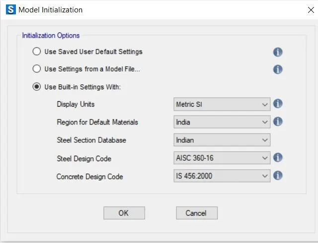
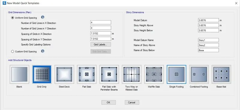
Single Footing was selected.
Subgrade modulus = F.O.S x S.B.C / max settlement
= (3x150) / 0.05 = 9000 KN/m³
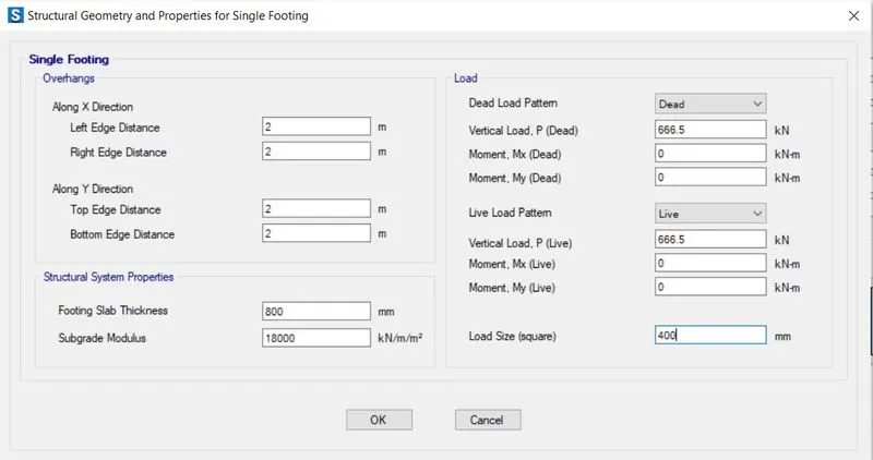
The compression axial load for the load combination (1.5DL + 1.5LL) is 2000 KN.
Unfactored load = 2000 / 1.5 = 1333.3 KN
Dead load breakup= 1333.3 / 2 = 666.5 KN
Live load breakup= 1333.3 / 2 = 666.5 KN
Therefore, Footing thickness 800 mm.
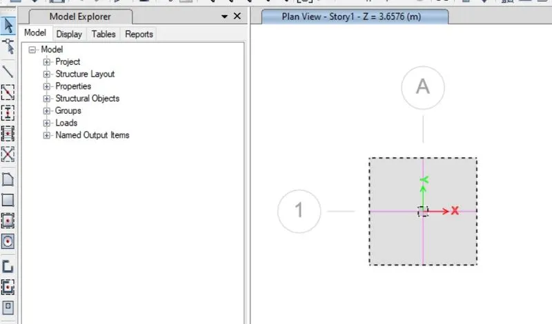
Step : 02
- Define materials
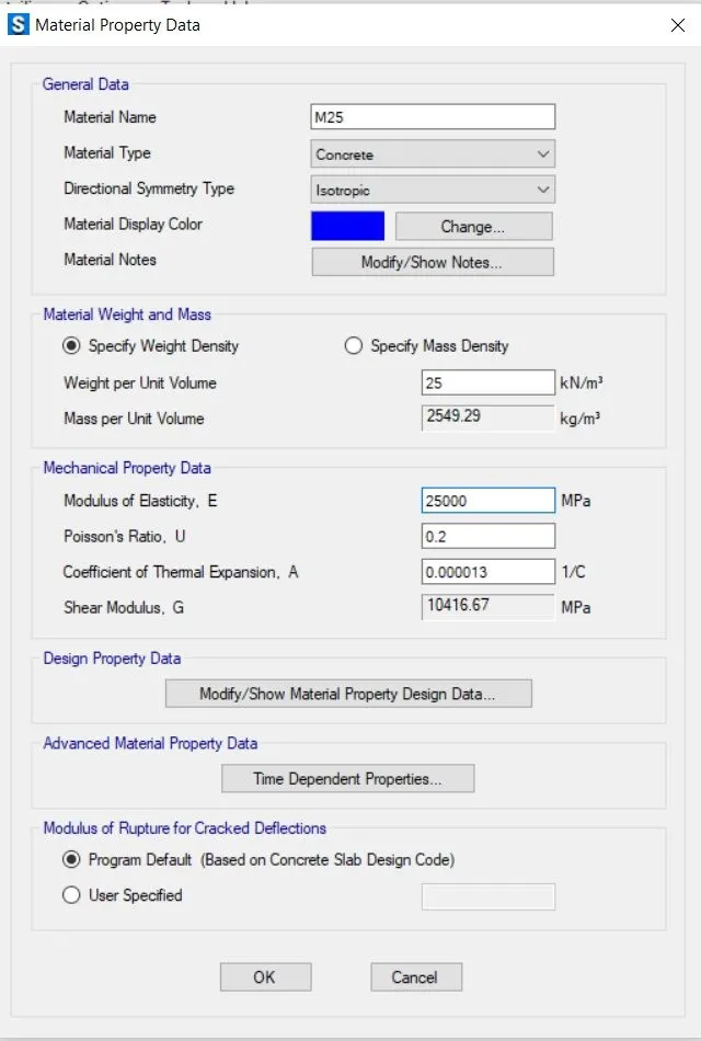
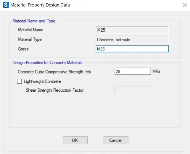
- Add new material property, M25 concrete.
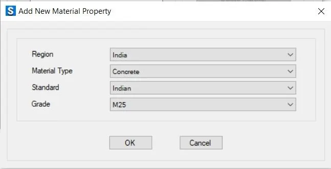
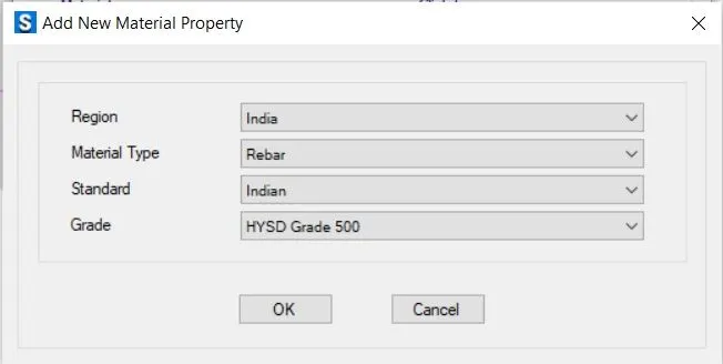
- Add rebar Fe500
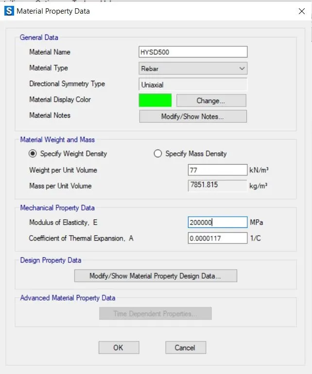
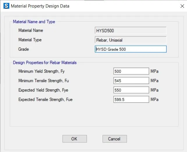
- Material property data :-
Click define > material properties
Rebar yielding strength(Fy) = 500 N/mm²
Rebar ultimate strength (Fu) = 545 N/mm²
M25 grade of concrete
Modulus of elasticity
E = 25x5000 = 25000 N/mm²
Step : 03
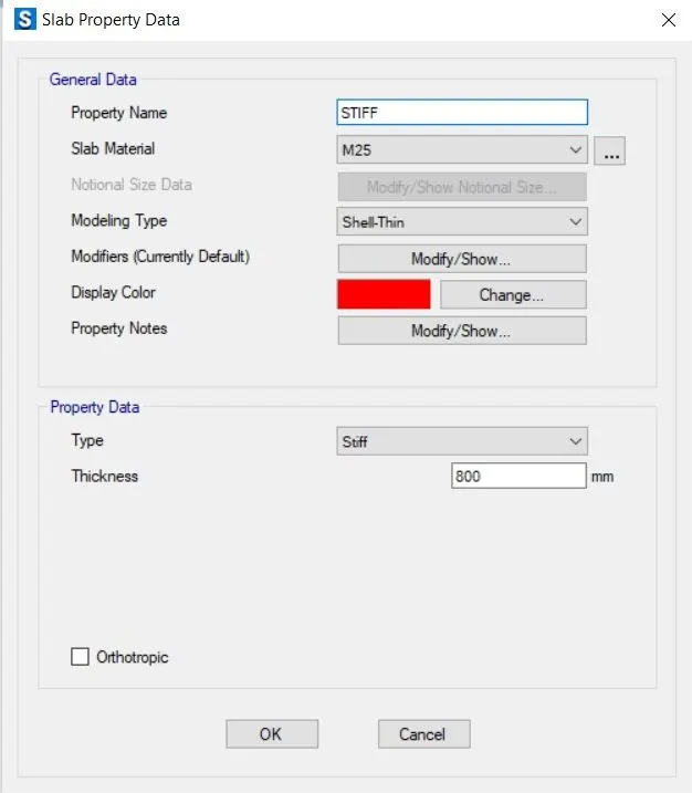
- Define Slab properties.
- Define properties for footing.
- Define properties for Mat.
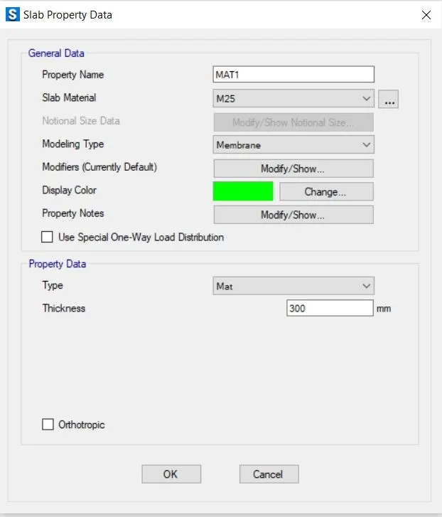
- Define properties for Stiff.
Step : 04
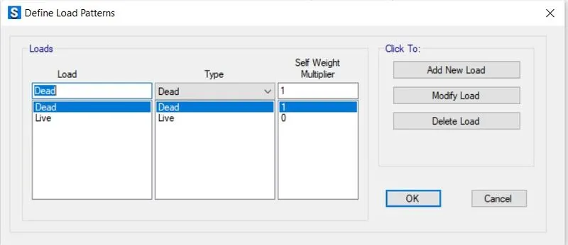
- Define Load pattern.
Step : 05
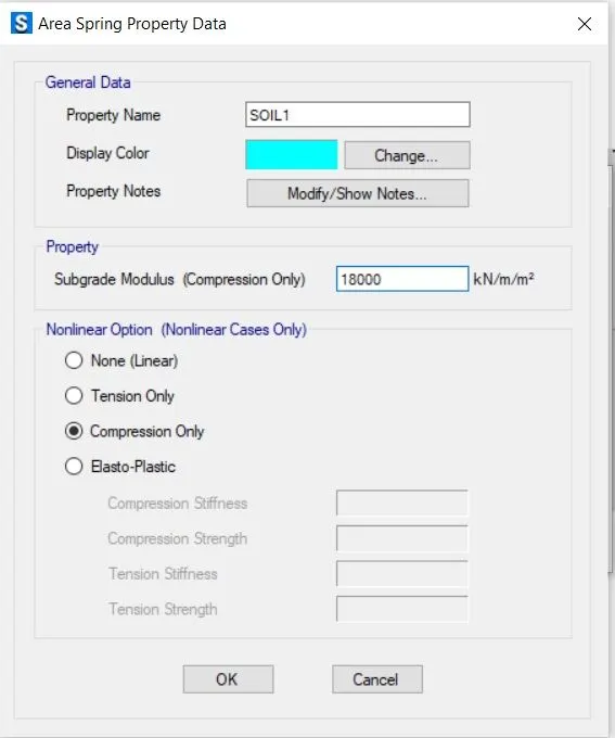
- Define the modules for soil subgrade and area spring properties.
Step : 06
- Assign Point load.
Step : 07
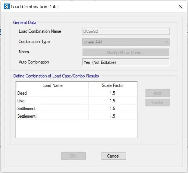
- Assign load combinations.
Step : 08
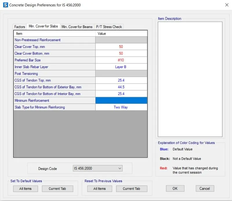
- Check your preferred design (minimum cover 50mm).
Step : 09
- Run Analysis & Design.
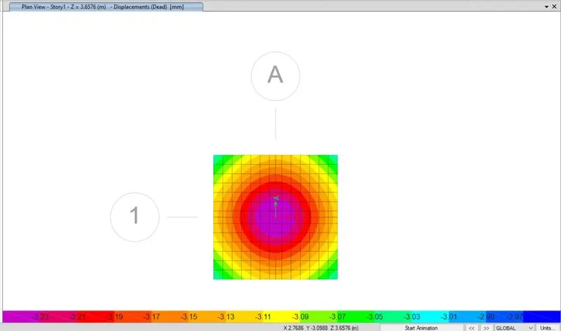
Step : 10
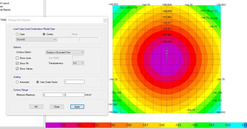
- Safe bearing capacity under service load is 152 KN/m2
Step : 11
- Two way shear check.
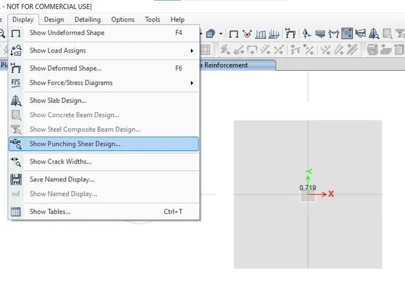
Two-way shear is 0.719, Hence OK.
Step : 12
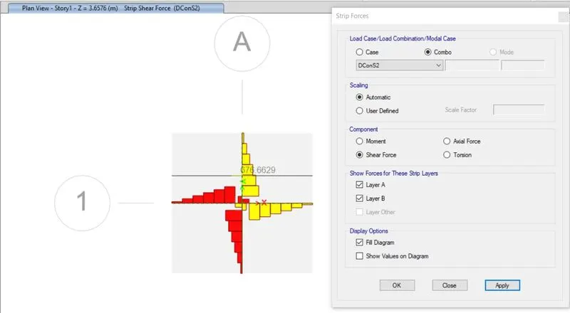
- Ultimate Bending moment & shear force check.
Bending Moment :-
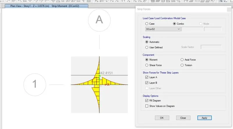
Shear Force :-
Step : 13
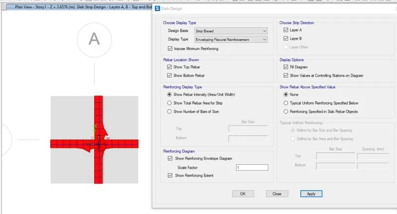
- Flexural Reinforcement design for Footing slab.
RESULT :-
- SAFE software was effectively used to design and analyze the isolated footing.
- The acceptable safe bearing capacity under service load is 152 KN/m2.
OK because two-way shear is 0.79. - Successful completion of the ultimate bending moment and shear force check.
- Successful design of flexural reinforcement for the slab supporting the footing.
Q2). A column of size 600x600 carrying an unfactored gravity load (DL+LL) of 1175 KN is to be supported on pile cap, which ultimately transfers load to the piles underneath. Piles of 16 metres length and 500 mm diameter are to be used. Each pile has a load carrying capacity of 200 KN. Model, analyse and design the pile cap on SAFE to evaluate the following:
- Pile group to be used
- Depth of pile cap
- Longitudinal steel on top and bottom face in both directions
Note : Participants must refer to IS 2911 (part 2) and SP 34 for 2nd challenge
Ans :-
AIM :-
- The pile cap was modeled, examined, and designed using SAFE.
- to evaluate the subsequent.
- There will be a pile group.
- stack cap depth
- Steel faces top and bottom longitudinally in both directions.
Procedure :-
Given.
Column size = 600 x 600 mm
Unfactored load = 1175 KN
Pile length = 16m
Pile diameter = 500 mm
Load carrying capacity = 200 KN.
Calculations :-
Number of pilers = 1175 / 200 = 5.6 = 6
Spring constant = ExA / L
Where, E = 25000 N/mm²
A = (π4)">(π4)(4)(500)² = 196375 mm²
L = 16000 mm
Spring constant =25000 x 196375 / 16000=306835 N/mm or 306835 KN/m
Edge spacing is taken as 200 or 300 mm.
Step : 01
- Open the SAFE Application.
- Select New model.
- Followed by input settings, units was selected as metric and code Is 456-2000.
Step : 02
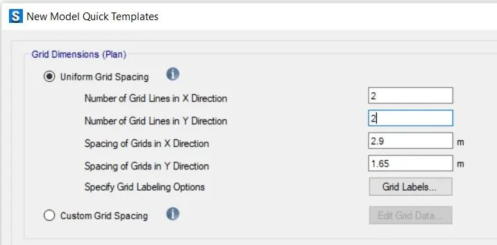
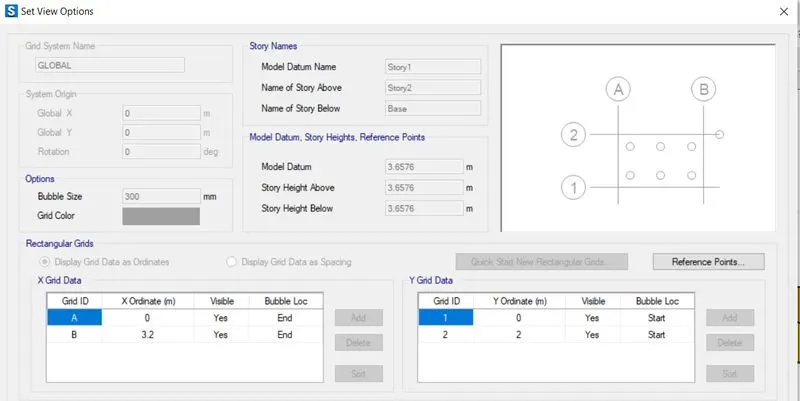
- Co-ordinates was defined next.
- Grid spacing in X-direction and Y-direction was taken as 3.20m and 2.0m respectively, as shown below.
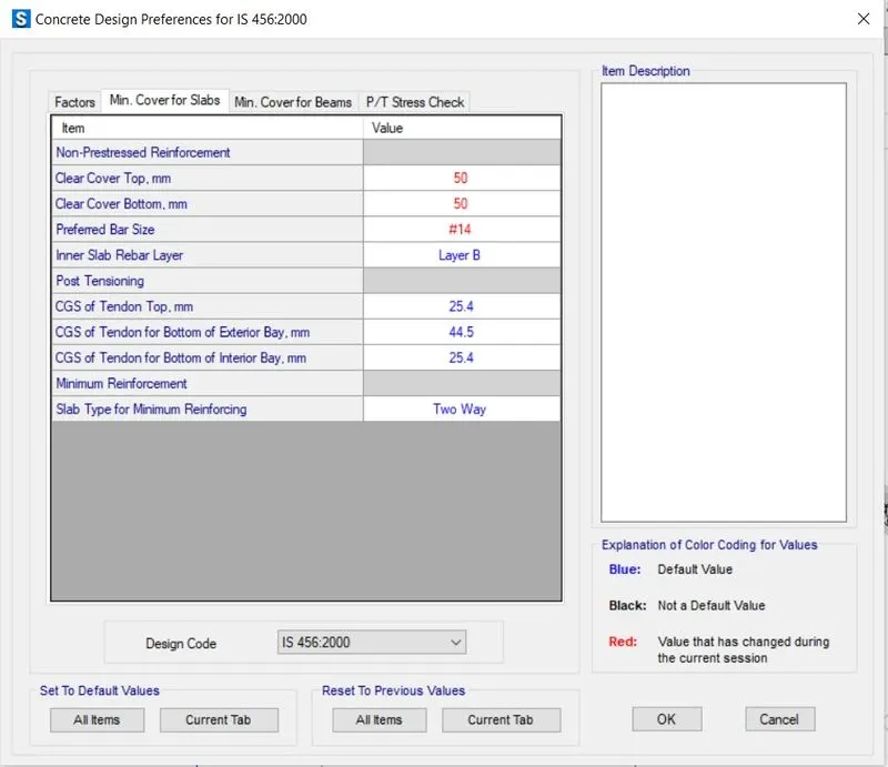
- Check design preference (min cover 50mm)
- The top and bottom covers were 50mm each, and the bar size was set at 14mm.
Step : 03
- Material property data:
Click define > material properties >M25 grade of concrete.
Modulus of elasticity
E = 25x5000 = 25000 N/mm²
Fe 500 rebar was added next as shown below.
- Add Rebar Fe500
Step : 04
- Define Slab properties.
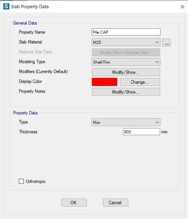
- Define pile cap.
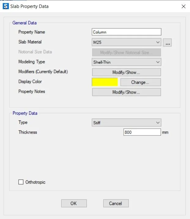
- Define column.
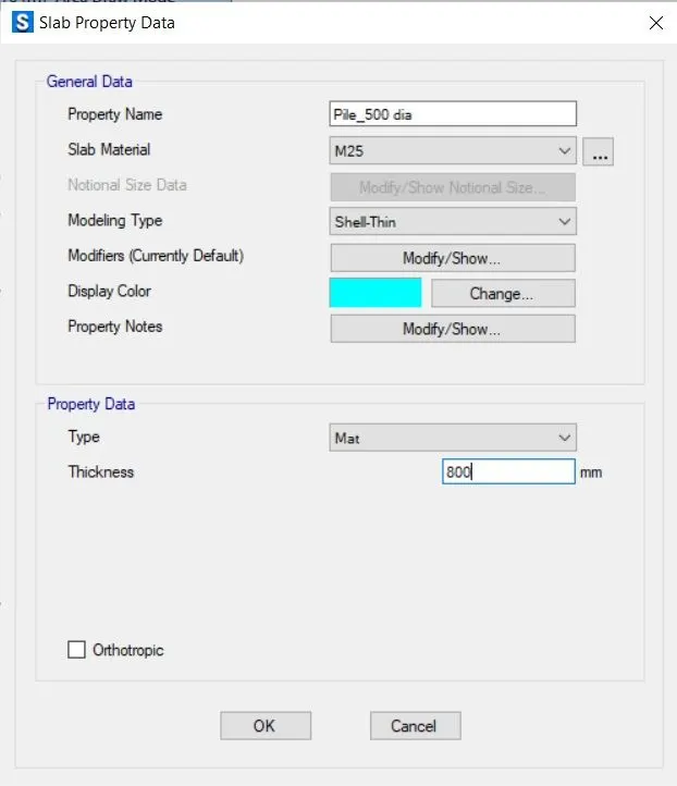
- Define pile_500 dia details.
Step : 05
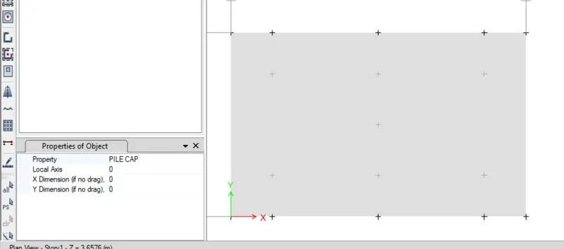
- Draw the slab by using quick draw tool > draw points.
Step : 06
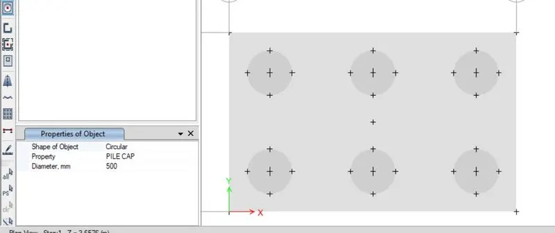
- Add piles at the point
- Modify the edge distance to 0.2m
Step : 07
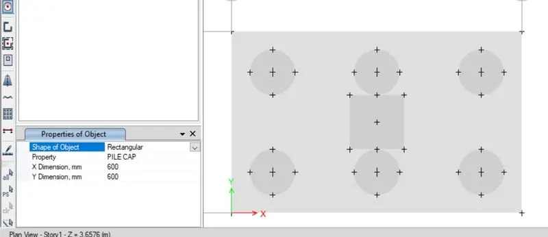
- Create a column of 600 x 600 mm
- Draw the column in center using quick draw tool.
Step : 08
- Spring were added.
- Define spring property data, as shown below.
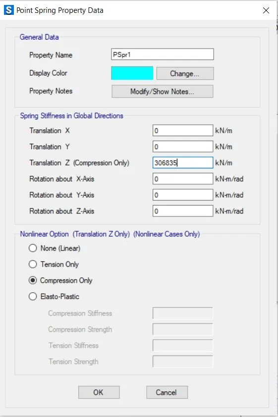
- Select pile > assign > support data > point springs.
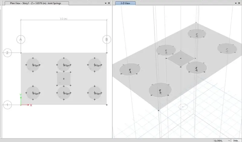
- Springs' constant is derived from the calculation above.
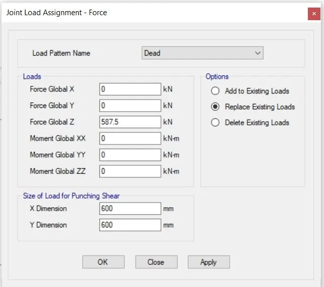
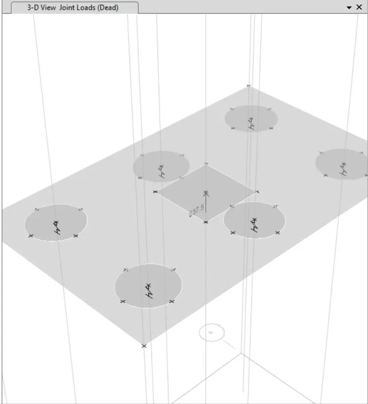
- Next, 587.5 KN of dead and live load are added.
Step : 09
- The next defined combination was the load case.
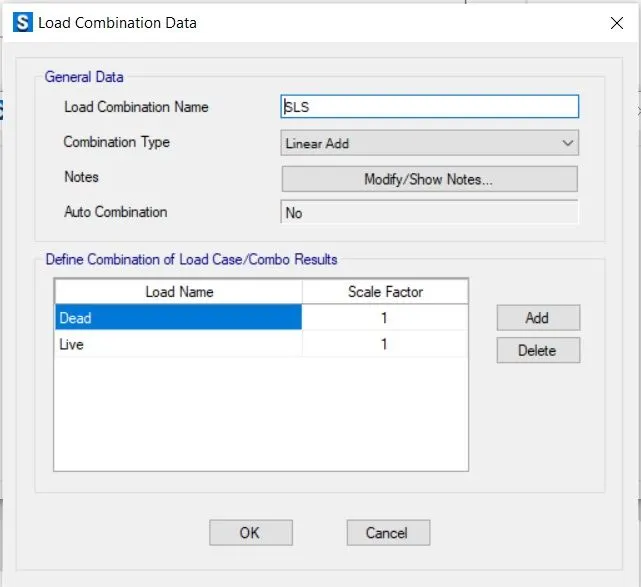
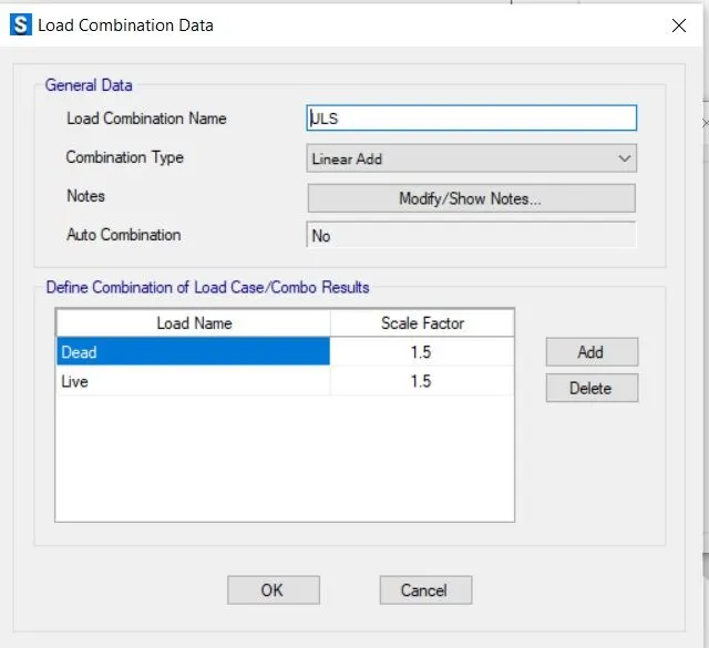
- Run the analysis after defining the load combination.
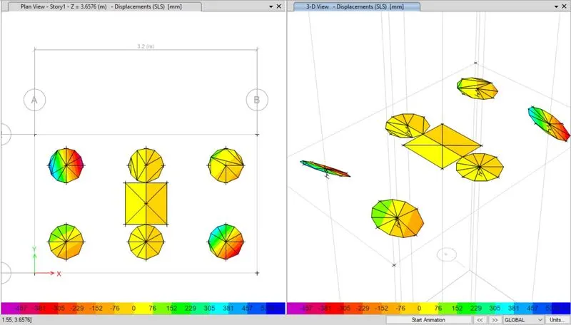
- Max displacement was found as shown, So its Safe.
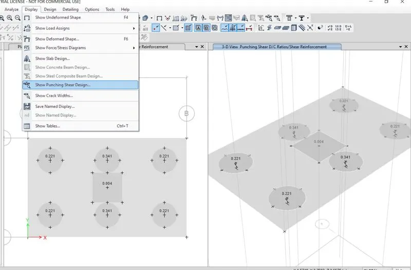
- Additionally, all punching shear values are lower than 1, making it safe.
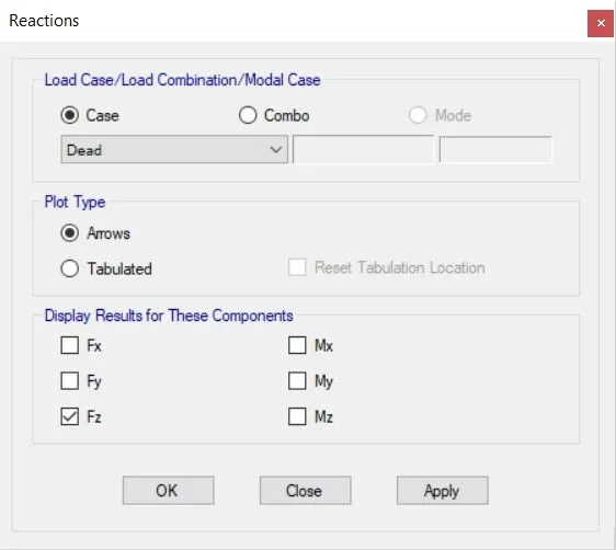
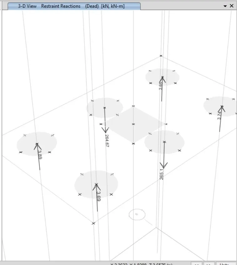
- Joint reaction diagram, safe because all reaction forces are in accordance with the limit.
- The next step is to add the reinforcement details, as shown in the X- and Y-directions.
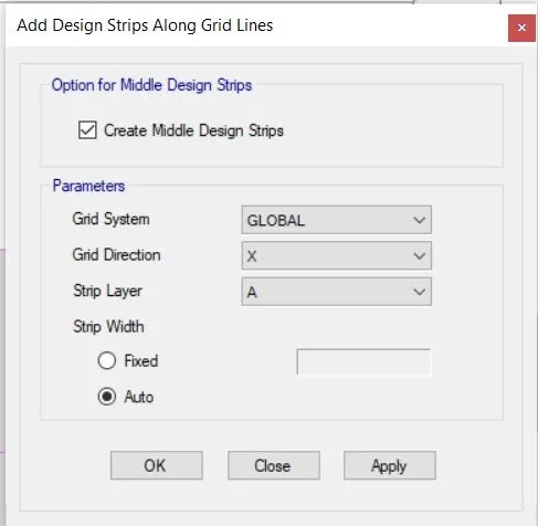
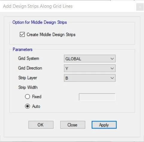
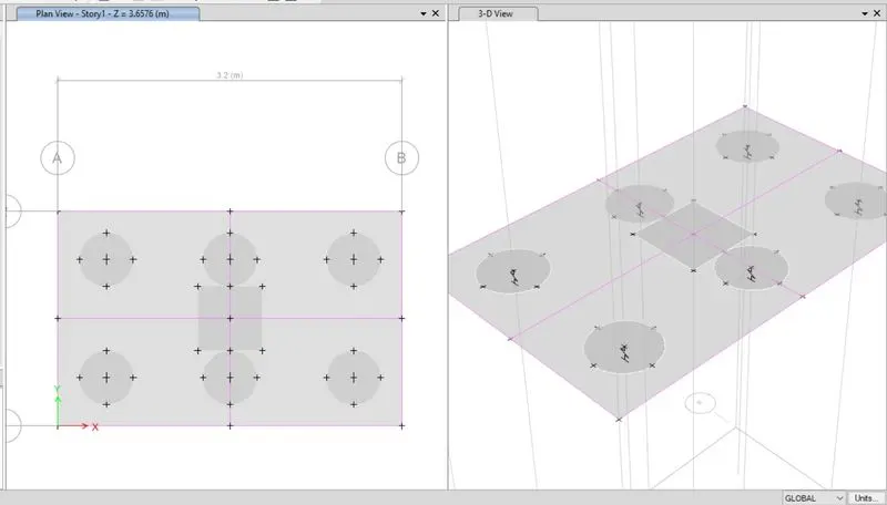
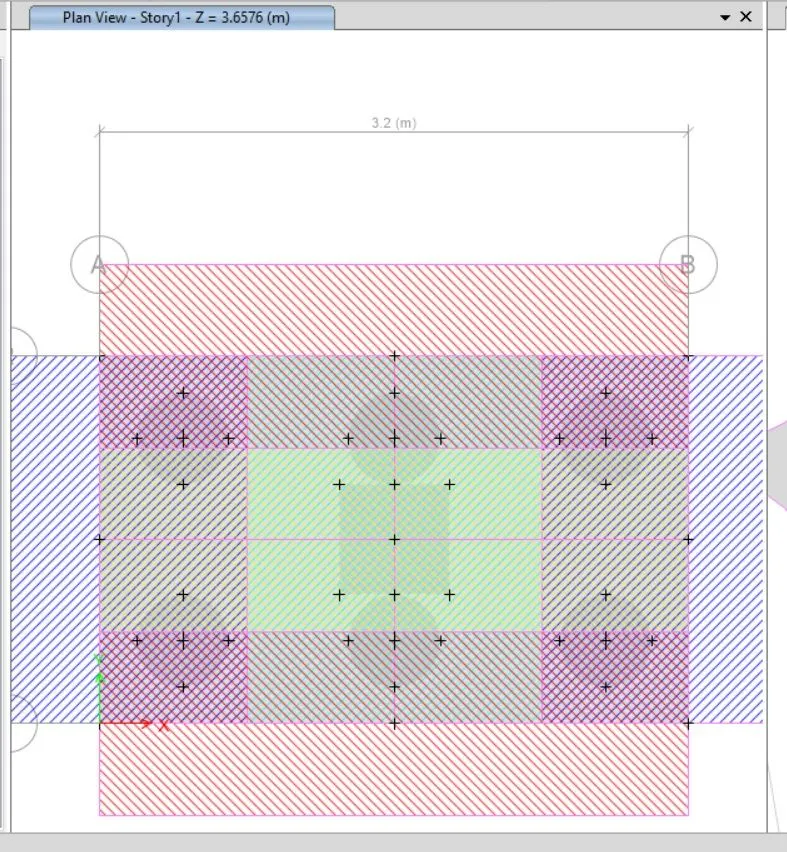
- Run the analysis again.
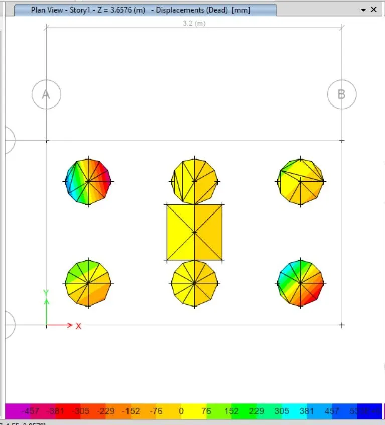
Step : 10
- Reinforcement Slab Design.
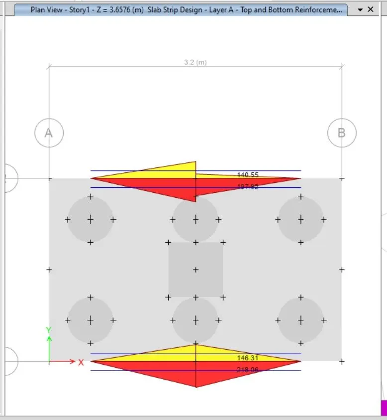
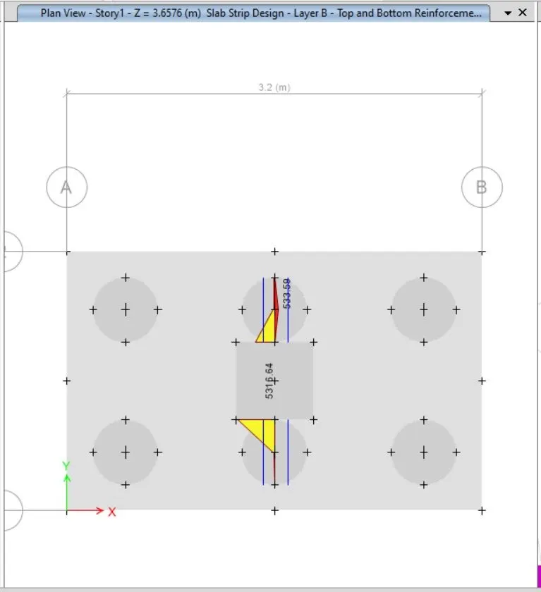
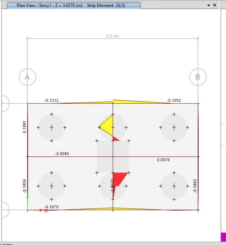
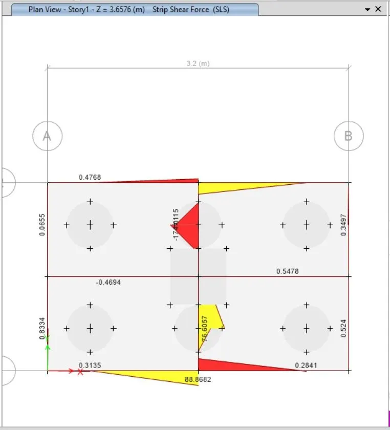
- Pile cap foundation design or a shear force and bending moment check.
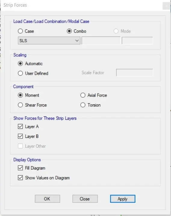
Bending Moment :-
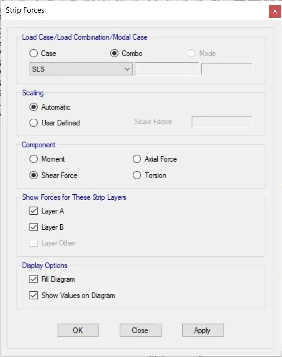
Shear Force :-
RESULT :-
- SAFE software was used to successfully design the pile cap foundation.
- As can be seen, the maximum displacement was found, proving that it is secure.
- It is secure because none of the punching shear values are greater than one.
- The final checks for bending moment and shear force were successful.
- Flexural reinforcement for the slab's design was successfully finished.