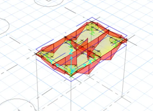
Foundation Design using SAFE
QUESTION-1
Introduction:
As per the isolated footing in week-11 challenge, model in safe, analysis and design of the foundation and to arrive the steel reinforcement.
Aim:
- To Analyze and designthe isolated footing from week 11 challenge on SAFE
- To verify the size, depth and steel provided as per calculations.
Procedure:
Create new model then go to input the metric units byusing code usage IS 456-2000
Step:1
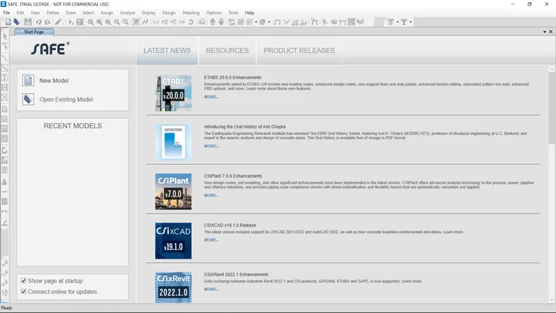
Open the SAFE Application
select New Model
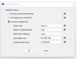
followed by Input Settings,
Units was selected as Metric and Code IS 456-2000.
Step:2
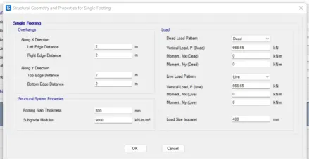
In the window for default, Select single footing,
Input the required dimensions and loadings in the respective locations.
Subgrade modulus of the soil=FOS x SBC / settlement of soil
Where SBC=150kN/m2
Factor of safety (for footing)=3
Considered settlement of the soil =50mm
Subgrade modulus=9000kN/sq.m
For load combination of 1.5(DL+LL), the resultant compression axial load =2000kN
Unfactored compression axial load =1333kN
Dividing to DL & LL =1333/2
=666.65kN
For column size the provided square footing is 400x400
The assumed concrete footing thickness in 0.8m
Step:3
Material definition:
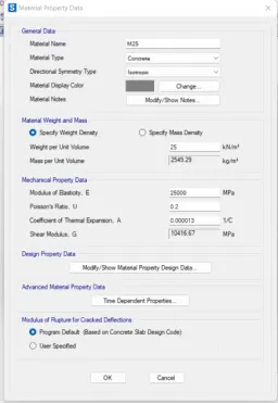
Defining material property, Concrete M25.
Modulus of elasticity =E=25000 N/mm2
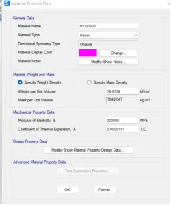
Defining rebar details:
Reinforcement material added for HYSD 500 and the respective material properties are all inputed.
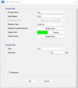
Step:4- SECTION PROPERTIES
Defining the section properties of the model.
Define> Slab porperties
For footing the slab is considered as Mat type property and considered thickness of 300mm thick.
Defining the stiffened member using same as the slab property definition- slab stiff options as given below,
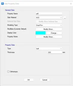
For footing, the slab thickness is assigned as 800mm thick and the slab type is considered as Footing,
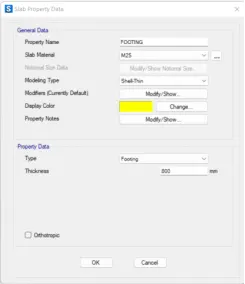
Step-5 -Load Assignments:
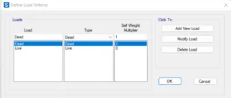
Defining the load patterns for dead and live load I,
Define goto load pattern and set Dead & Live load added.
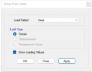
Select the point of column resting location, assigning the dead and live load
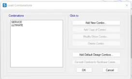
After the load assignments assign the load combinations,
For ultimate and service load combinations.
Step:6 – Design strip
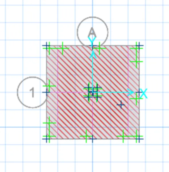
Adding the design strips in X & Y direction , for the width of the slab.
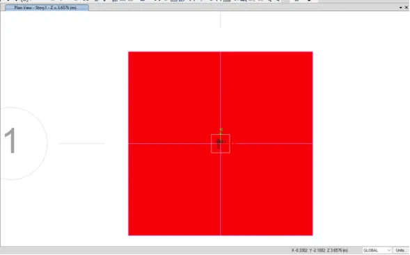
CSA-1 & CSB-1 strips are added.
Step:7 - Analysis
Analyse and goto perform analysis.
Displacement:
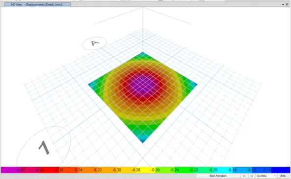
Since only 6mm deflection which is allowable minimum deflection only.
Step :8 – SLAB DESIGN
For the strip width in X & Y direction , the bending moment of the slab in X & Y direction is observed.
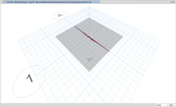
X-Direction strip: (Reinforcement required)
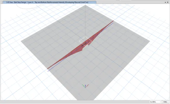
Y-Direction Strip: (Reinforcement required)
STEP: 9
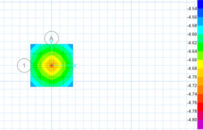
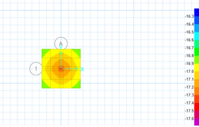
run analysis and design
RESULT:
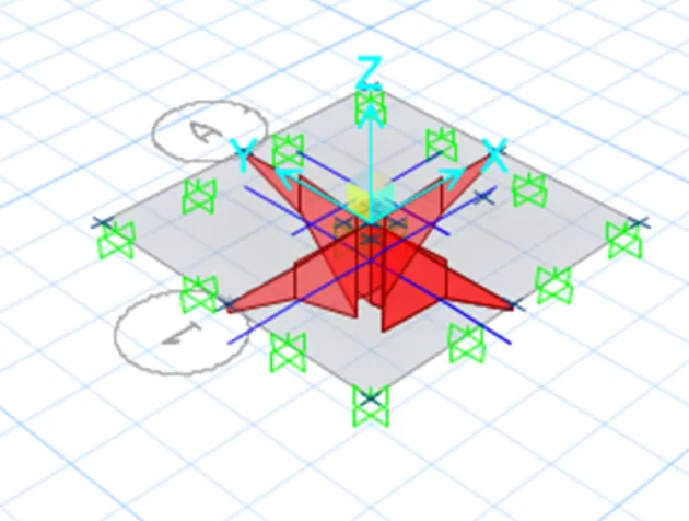
Hence, the isolated footing was designed and analyised in SAFE successfully.
Conclusion:
Thus,the X & Y direction footing reinforcement requirement is obtained by analysis and design by safe software.
QUESTION-2
Design of pile foundation:
Aim:
To model, analysis and design of pile cap using the SAFE software, and finalize the dimension of the pile cap and arriving the top and bottom reinforcement of the pile cap.
Procedure:
Step:1 –(Calculation of NO of piles and pile spacing)
Given:
Column size -600x600mm
Axial load (unfactored)=1175kN
(to be supported on the pile cap)
Specification of pile:
Pile length =16m
Diameter of Pile =500mm
Loading capacity of each pile = 200kN
Calculation of no. of pile:
No. of pile= Axial load/capacity of single pile
=1175/200
=5.8
Which is approximately 6 nos of pile to be designed.
Spring constant =(EA)/L
Where E is considerd as 25000N/Sq.m
Area of pile ,A=3.141*500^2=196349 Sq.m
I=16000mm
=(25000x196349)/16000
=306795 N/mm
Minimum spacing between the pile =2.5 x diameter of the pile
=2.5 *500 =1250mm
Edge spacing considered =200mm
Step:2 (Modelling in SAFE)
Open new model in SAFE
Create new model goto input the metric units to code usage IS 456-2000
Step:3
Open blank model and then using the dimension of the pile cap calculated above, the preliminary plan is draw in the X-Y cartesian plan.
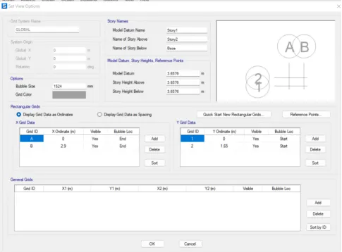
Using the grid system , the required dimension of grids are added.
Step:4
Material properties:
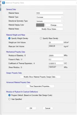
Defining material property, Concrete M25.
Modulus of elasticity =E=25000 N/mm2
Defining rebar details:
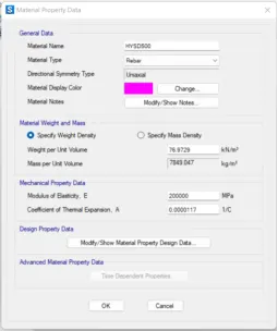
Reinforcement material added for HYSD 500 and the respective material properties are all inputted.
SECTION PROPERTIES
Defining the section properties of the model.
Define Slab properties
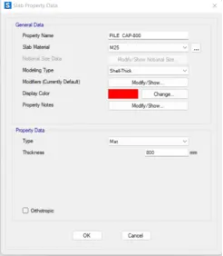
For Pile cap the slab is considered as Mat type property and considered thickness of 800mm thick.
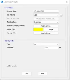
At column resting location, the stiffer column member is added,
For Column Stiffener the slab is considered as Stiff type property and considered thickness of 800mm thick.
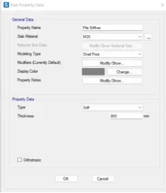
At Pile supporting location, the stiffer pile member is added,
For Pile Stiffener the slab is considered as Stiff type property and considered thickness of 800mm thick.
Step:5- Modelling of the slab.
>Adding the pile cap of 800 thick to the model using the quick floor area toolbar.
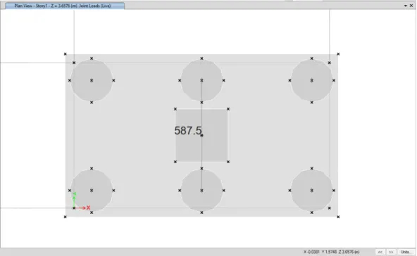
And the points of the pile resting locations are added using the draw points to replicating the points for 1.25m for 2 nos of piles
Using the quick add floor area tool bar, the pile support stiffeners are added.
The edge distance is not enough so the slab is extended by 100mm.
Add springs,
Piles to assign and spring support, at the pile supporting location.
Spring constant =EA/L
=(25000x196349)/16000
=306795 N/mm
=3.6.795 kN/mm
At column resting location, the column stiffeners are added. And then the point loads in DL and LL of 587.5 kN are added.
Step-6 -LOAD ASSIGNEMENTS
Defining the load patterns for dead and live load I,
Define load pattern and goto Dead & Live load added.
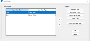
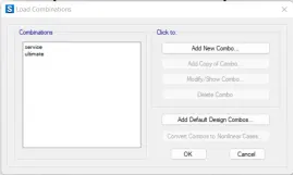
After the load assignments assign the load combinations,
For ultimate and service load combinations.
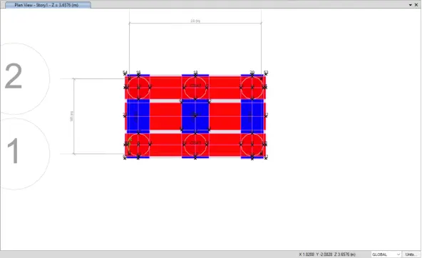
Step:7
Design strips for reinforcement calculation is added in the slabs in X & Y direction as shown below,
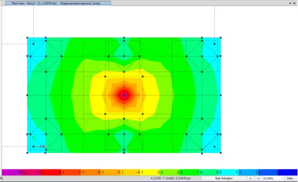
Step-8-Analysis and checking of model
Step:9
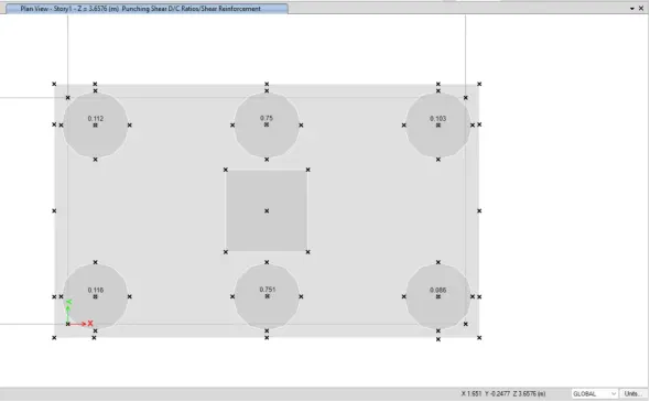
Punching shear is checked as per the IS Codal recommendation allowable limits.
Step:10
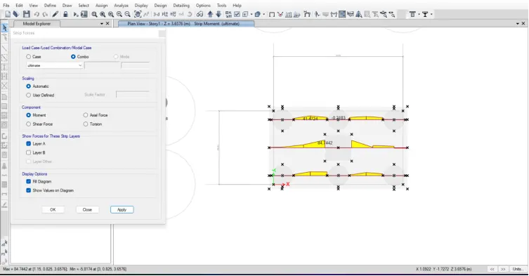
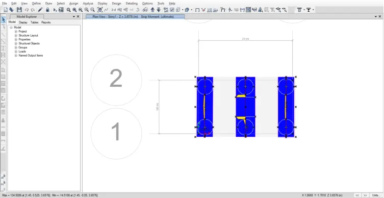
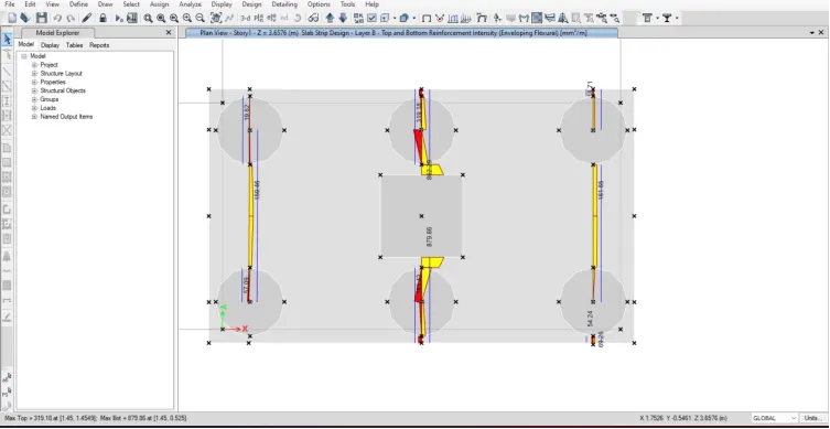
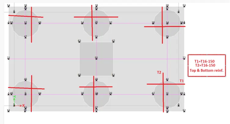
Reinforcement of X and Y direction from the strip results arrived from the below results.
X-direction:
Y-direction:
Auto calculated reinforcement by safe software:
Reinforcement X-Direction:
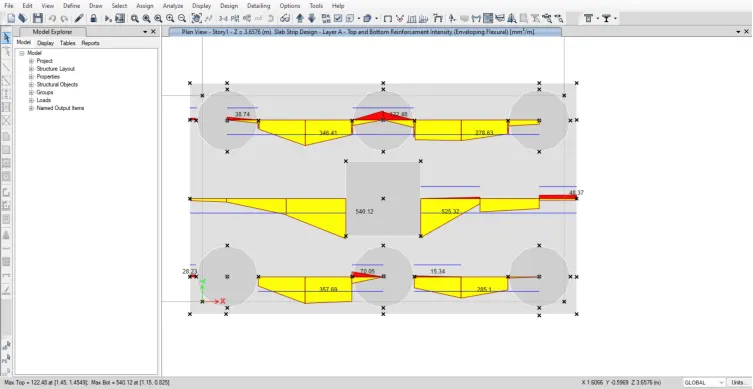
Reinforcement Y-Direction:
Reinforcement Detailing:
RESULT:
Complete design of pile cap foundation using SAFE software.