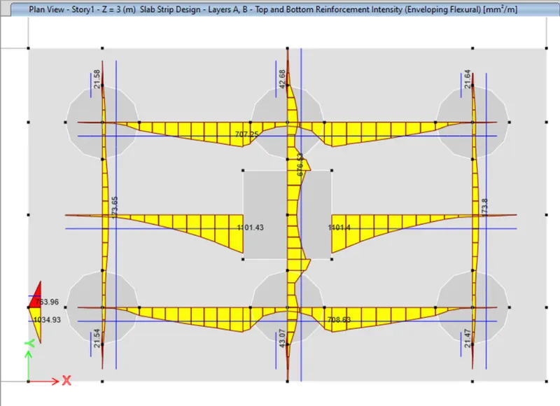
Foundation Design using SAFE
- Model the isolated footing provided in week 11 challenge on SAFE. Analyze and design it to verify the size, depth and steel provided as per calculations.
AIM: To design the given an isolated footing in Week 11th challenge with the help of safe software and to know the idea and procedure of the Spread footing using SAFE software.
OBJECTIVE:
To know the general design procedure for spread footing with SAFE software.
PROCEDURE:
Assuming the sizes from week 11 challenge
Square footing for a column size of 400 X 400.
Compression axial load for the load combination of (1.5DL + 1.5LL) is 2000 KN.
The safe soil bearing capacity is 150kn/m2 at a depth of 2 metres below E.G.L
We have to assume M25 concrete Grade.
Now in SAFE software
- Successfully Install and open the SAFE software.
- Install the SAFE from CSI website.
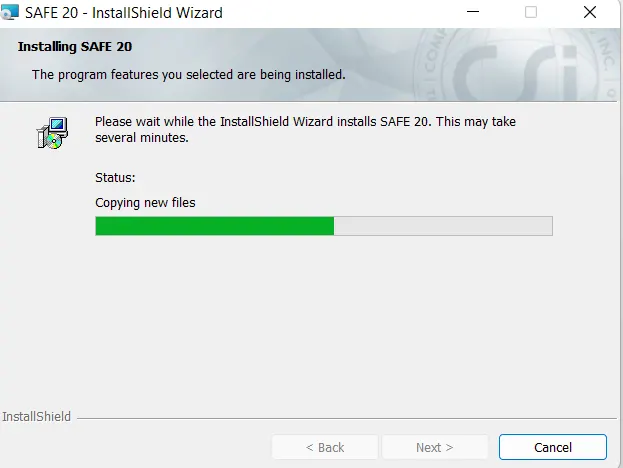
- Now right click on it and open it.
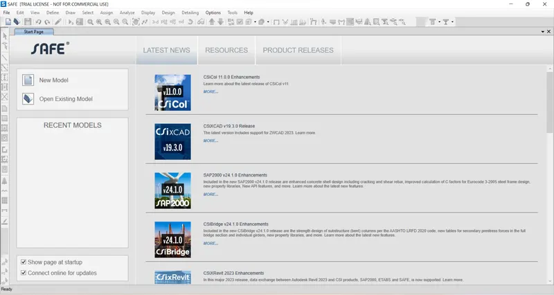
- The following interface will appear.

- Data require for SAFE analysis and Design
- Unfactored Load = 2000/1.5 = 1333.3kN
- Dead Load breakup = 1333.3/2 =666.7kN
- Live Load breakup = 1333.3/2 = 666.7kN
- Subgrade modulus for soil = Safe bearing capacity X factor to ultimate / maximum settlement = 150 X 3 /0.05 =k = 9000kN/m3
- Rebar Yielding strength (Fy) = 500N/mm2
- Rebar ultimate strength (Fu) = 575 N/mm2
- Elastic modulus of M25 concrete = 25000 N/mm2
- Creating New Model in Safe software by using above data.
- Open the SAFE and click on New model
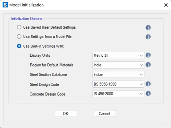
- Now use built In settings.
- From the below image given fill all the data
- Making of Footing
- Now a window will appear click on Single Footing
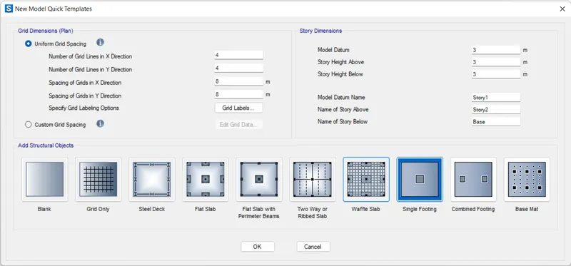
- Enter the values for column modulus etc.
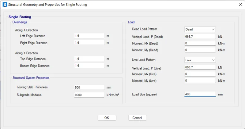
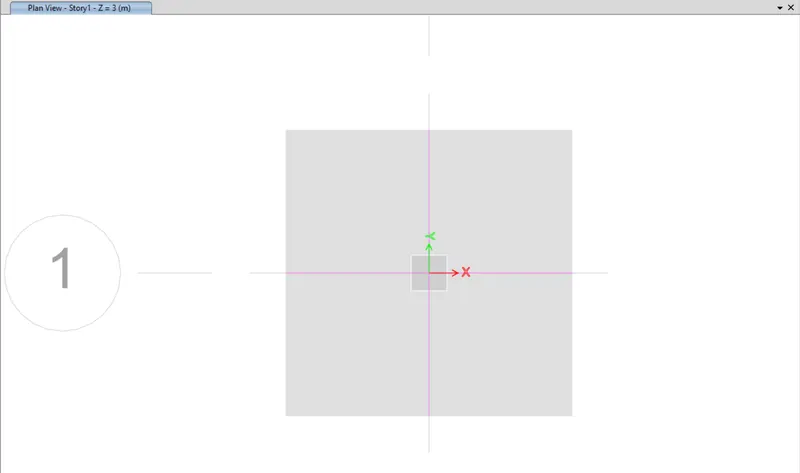
- Click on OK to see the footing.
- Now defining materials to the footing.
- Click on define>Material properties
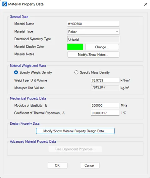
- A dialogue box will appear.
- Add new material as concrete M25
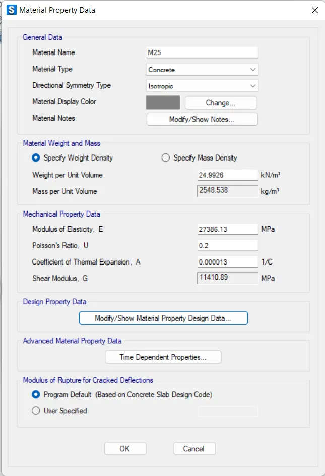
- And again add new material as Fe 500.
- Now define Section Properties.
- Click on define> Section properties
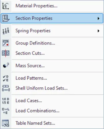
- A dialogue box will appear.
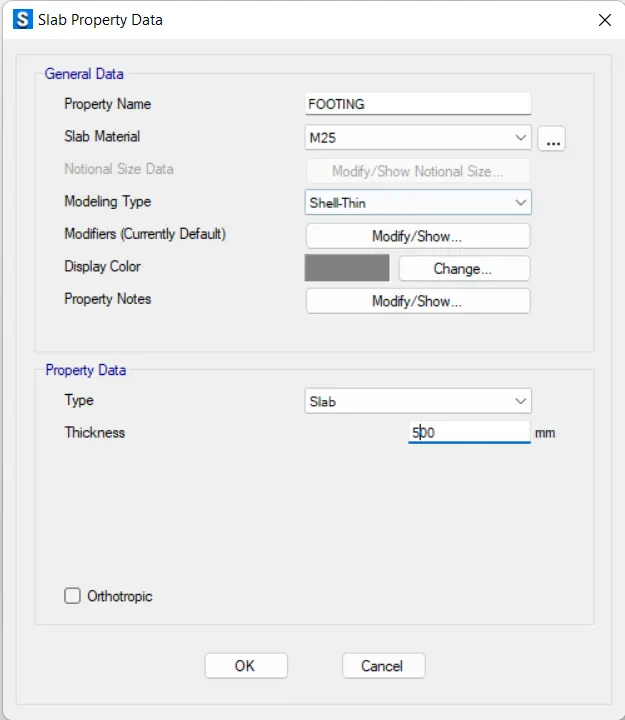
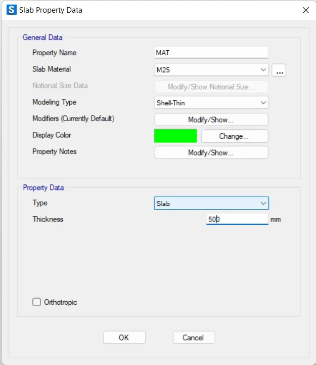
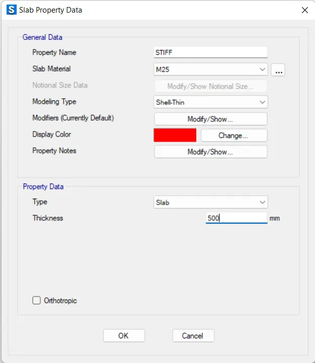
- Add separate properties as FOOTING, MAT, STIFF and for all these thickness should be 500.
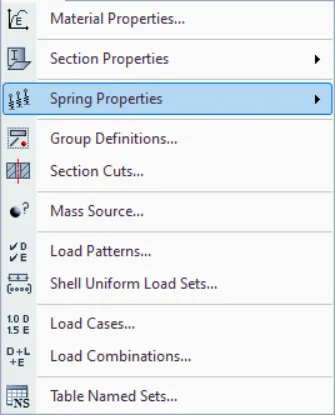
- Now add Spring properties.
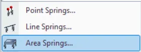
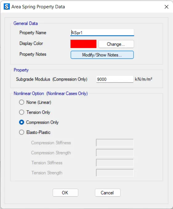
- Click on define> Spring properties>Area springs
- A dialogue box will appear.
- Add a spring by name as Asprn1
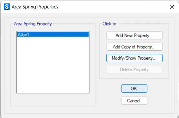
- Subgrade modulus = 9000
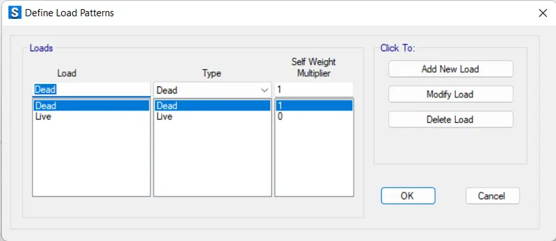
- Define Load pattern:
- A dialogue box will appear.
- Add Live load and dead load
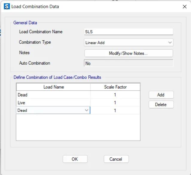
- Add Load Combinations
- A dialogue box will appear.
- Now add New Load as SLS (Serviceabilty limit state)
- And give the value for unfactored dead & live load as 1
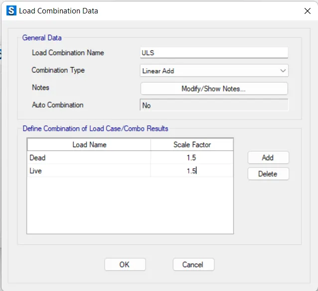
- Now add New load as ULS (Ultimate limit state)
- And give the value for factored dead & live load as 1.5
- Now Assigning area load on footing.
- Click on Assign> Shell> Area Spring
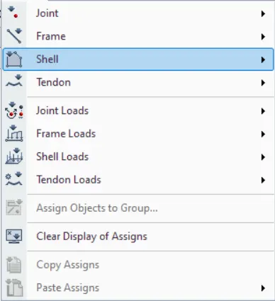
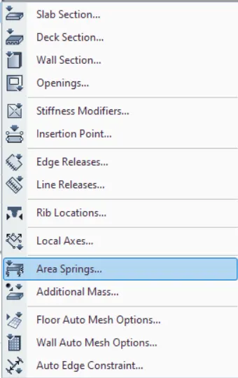
- A dialogue box will appear.
- Then select the Asprn1
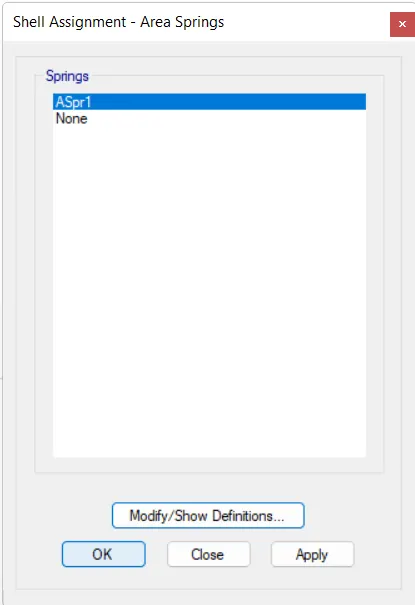
- And click OK.
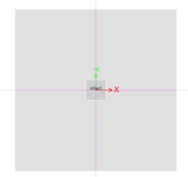
- Assign Joint Load On Column Point
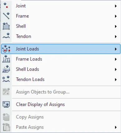
- Click on Assign>Joint loads>Force
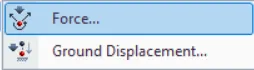
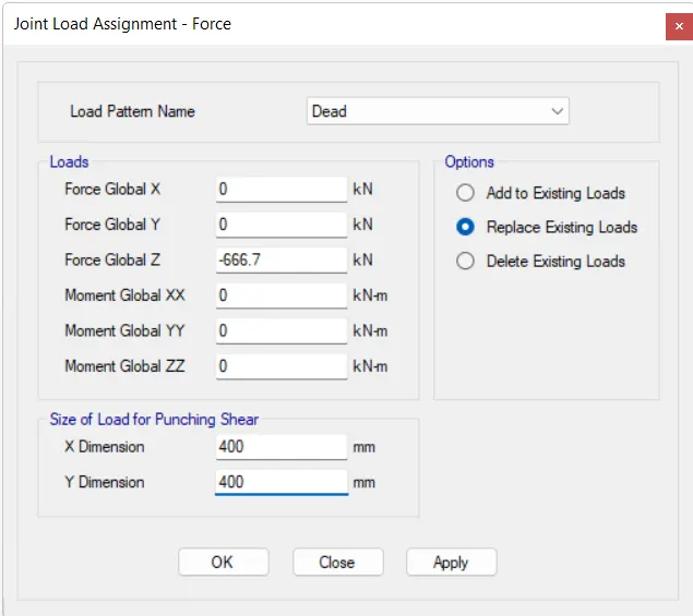
- A dialogue box will appear as Joint load assignment force
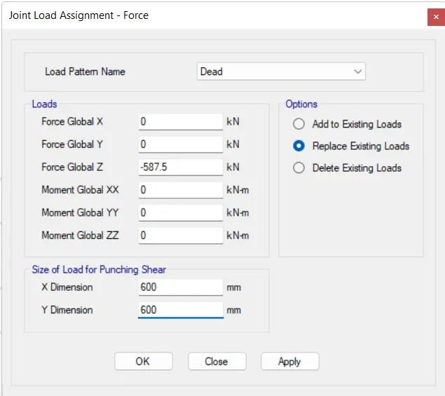
- Now select as Dead and give value as 666.7
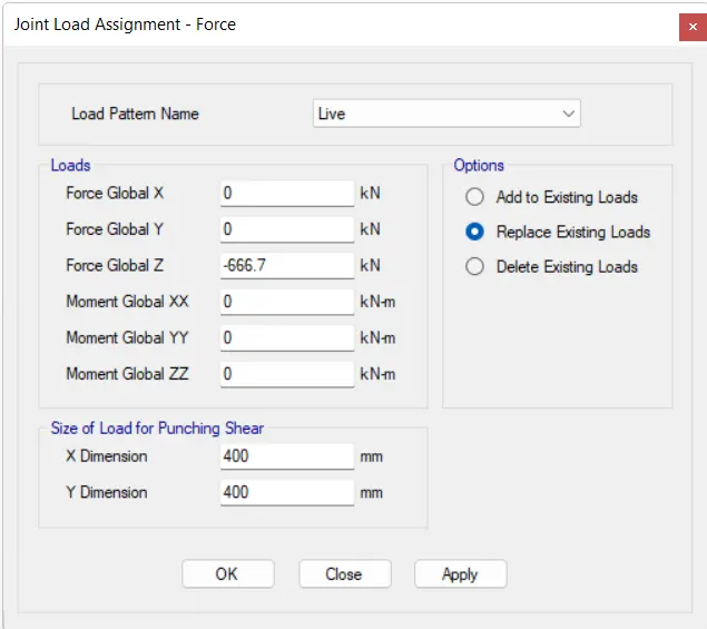
- Now repeat same for Live load.
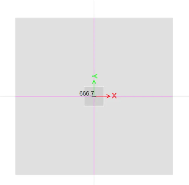
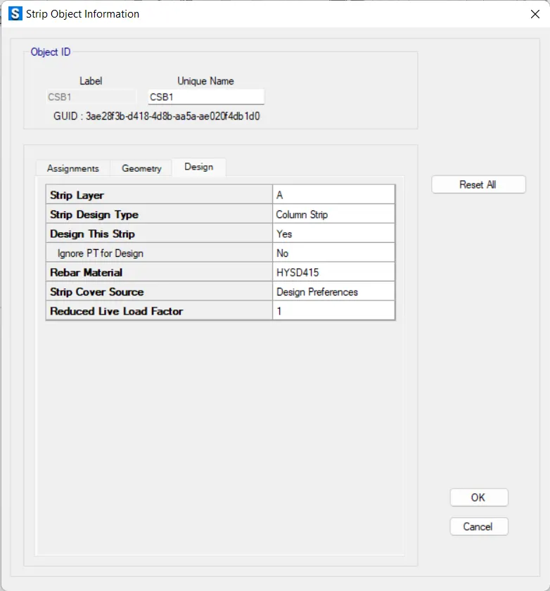
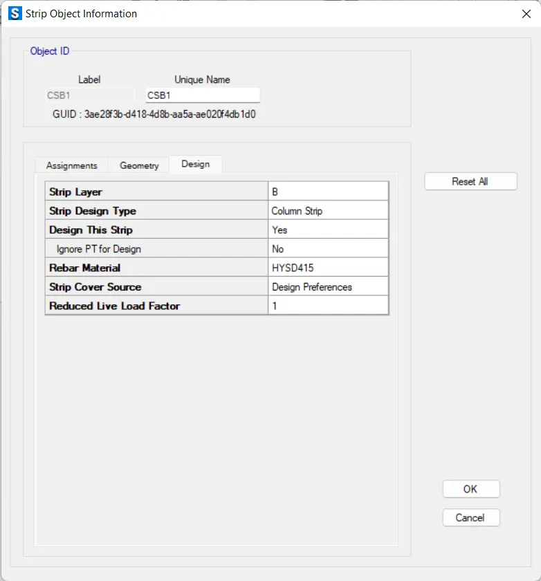
- Now Assign the Design Strip
- For this Select the X and Y strip
- Then right click on it
- A dialogue box will appear as Design Strip Information
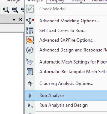
- Run the Analysis.
- Click on Analyze>Run analysis.
- Now save the file
- Now analysis will start this will show the max. deformation in your model.
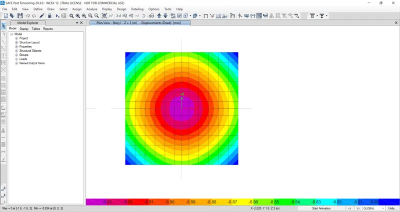
14. These checks are mandatory in the SAFE analysis.
- Two way shear check punching shear.
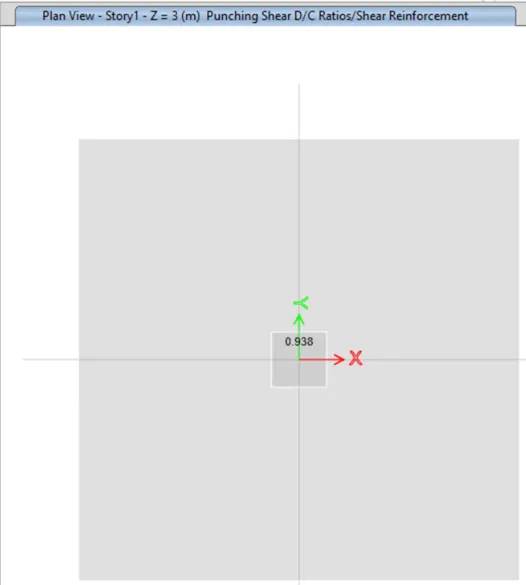
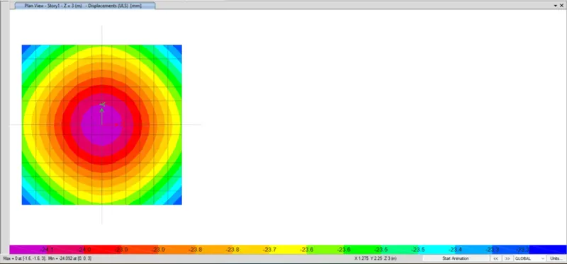
- Settlement under service load
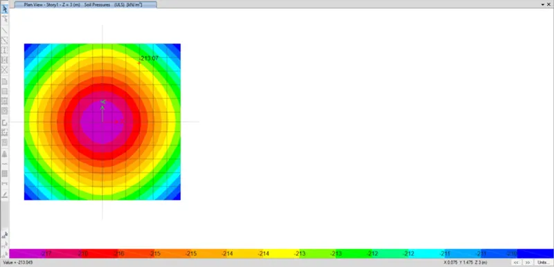
- Safe bearing capacity under service load
- Ultimate bending moment and shear
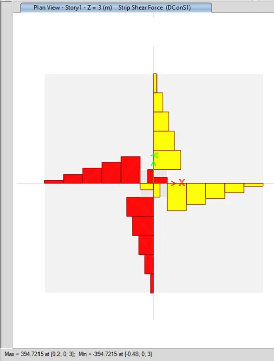
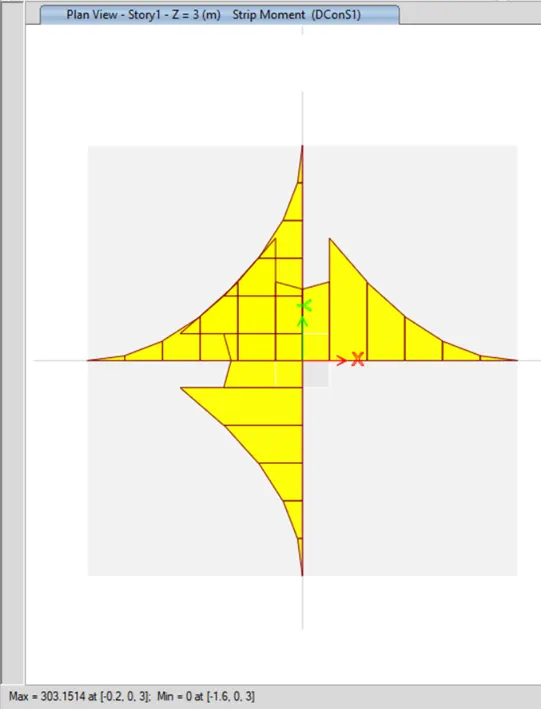
- A column of size 600x600 carrying an unfactored gravity load (DL+LL) of 1175 KN is to be supported on pile cap, which ultimately transfers load to the piles underneath. Piles of 16 metres length and 500 mm diameter are to be used. Each pile has a load carrying capacity of 200 KN. Model, analyse and design the pile cap on SAFE to evaluate the following:
Pile group to be used
Depth of pile cap
Longitudinal steel on top and bottom face in both directions
AIM: To design a pile foundation with given criteria and to know the general procedure of pile foundation with SAFE software
OBJECTIVE:
To Model the pile foundation on SAFE, analysed and design to obtain the result
Given data-
- Column size = 600 x 600
- Axial load (Unfactored load) = 1175kN
- Pile length = 16m
- Loading capacity of each pile is = 200kN
Data Required for the Safe Analysis and Design-
- Dead load breakup = 1175/2 = 587.5kN
- Live load breakup = 1175/2 = 587.5kN
- No of pile = axial load/ capacity of single pile = 1175/200 = 5.8 = 6 pile required
- So that area of pile = 3.14x500^2 = 196349m2
- Point spring of pile = (AXE)/L=(196349X2500)/16000 = 306796 kN/m
- spacing b/w pile = 2.5D = 2.5 x 500 = 1250mm
- Edge distance = 200mm
PROCEDURE:
- Creating New Model in Safe software by using above data.
- Open the SAFE and click on New model
- Now use built In settings.
- From the below image given fill all the data
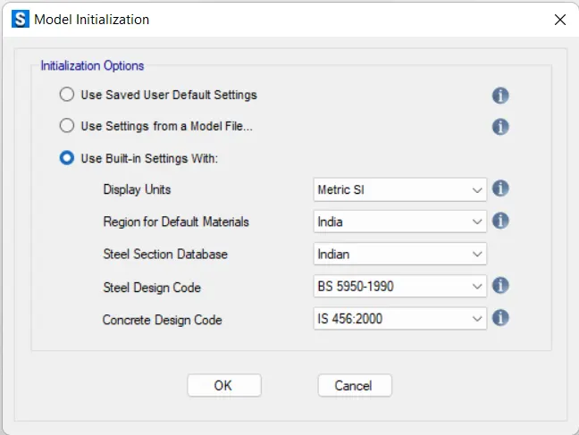
- Making of Foundation
- Now a window will appear click on Custom edit.
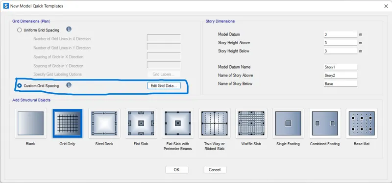
- Enter the values for column modulus etc.
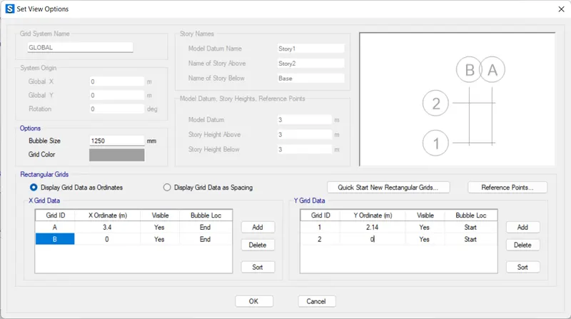
- Click on OK to see the footing.
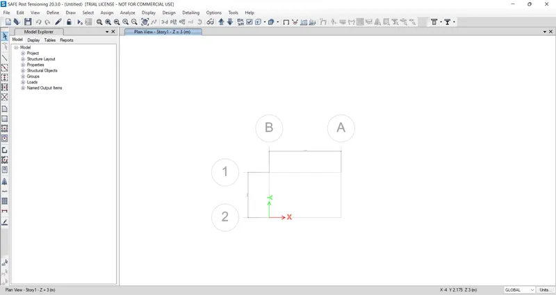
- Now defining materials to the footing.
- Click on define>Material properties
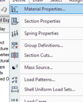
- A dialogue box will appear.
- Add new material as concrete M25
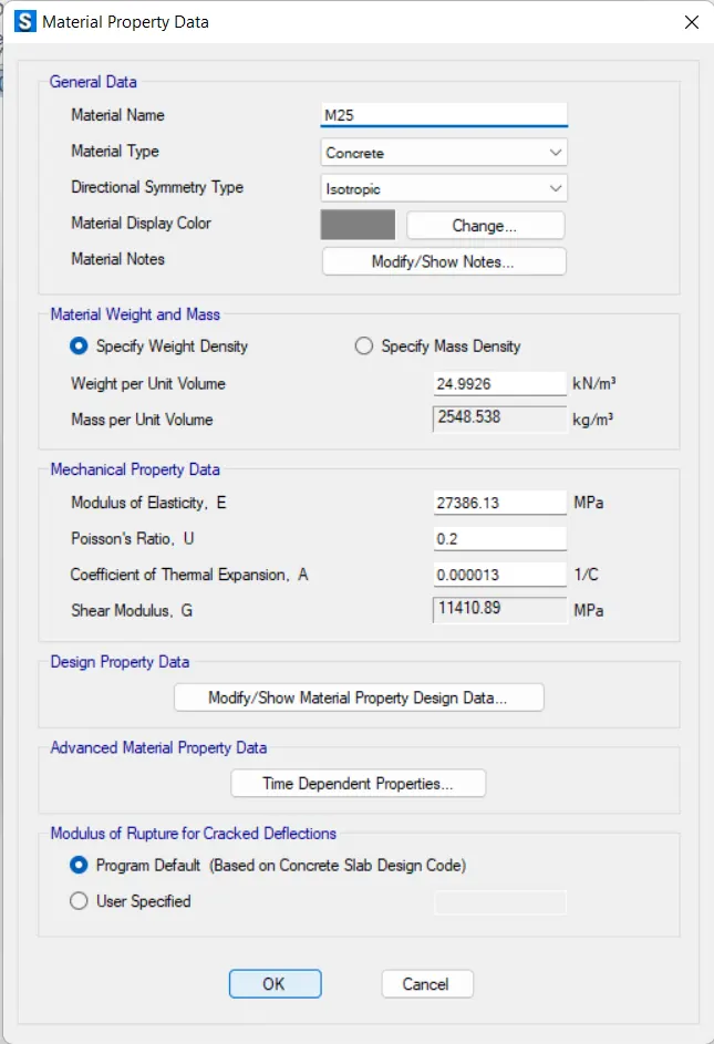
- And again add new material as Fe 500.
- Now define Section Properties.
- Click on define> Section properties
- A dialogue box will appear.
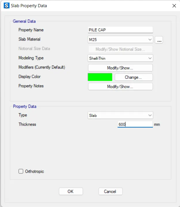
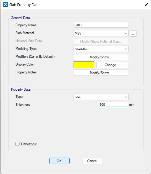
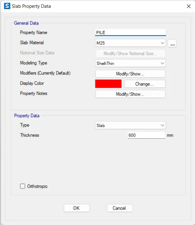
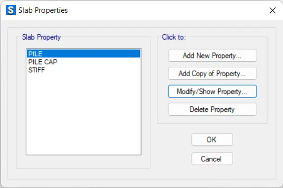
- Add separate properties as PILE CAP, PILE, STIFF and for all these thickness should be 600 as per the data.
- Now define point springs.
- Click on Define>Spring properties>point springs.
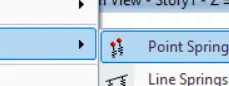
- A dialogue box will appear.
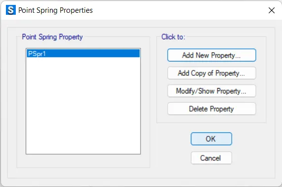
- Name as Pspr1
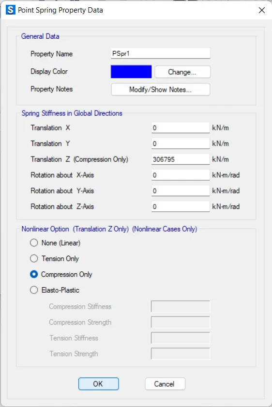
- Click on Ok.
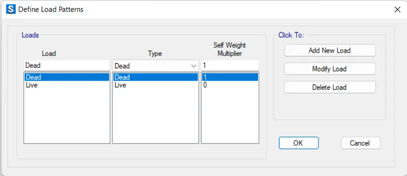
- Defining Load cases.
- Click on Define>Load cases.
- A dialogue box will appear.
- Add Live load and dead load
- Now Defining Load combinations.
- Click on Define>Load combination.
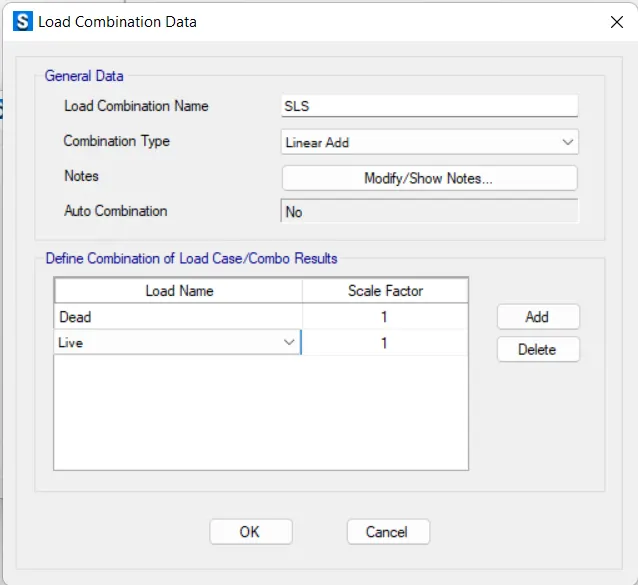
- Now add New Load as SLS (Serviceabilty limit state)
- And give the value for unfactored dead & live load as 1
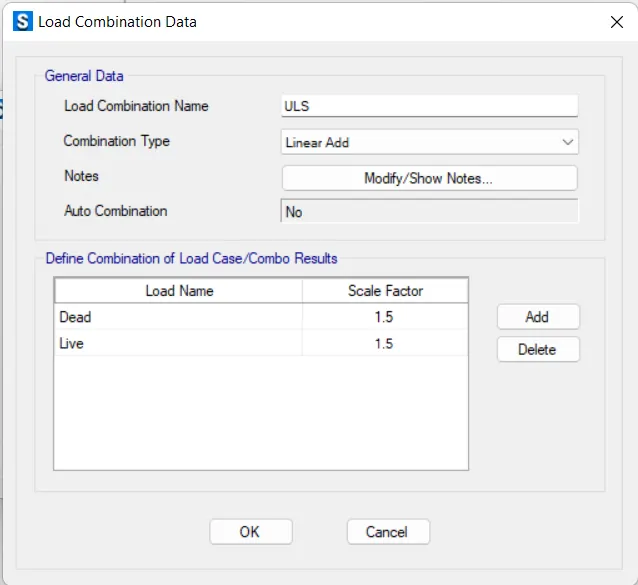
- Now add New load as ULS (Ultimate limit state)
- And give the value for factored dead & live load as 1.5
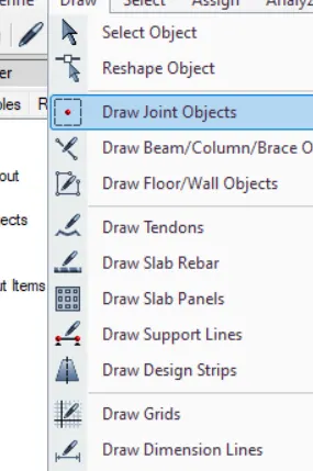
- Now we have to draw Joints for drawing pile
- Click on Draw> Draw joints objects
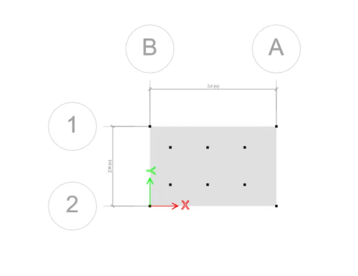
- In property browser mention the offset distance
- Draw a joint and by replicate option(by pressing ctrl + R) copy it.
- Now we have to draw Pile, Pile cap and Stiff
- Click on Quick draw point option
- Change the property as given
- Start drawing piles, stiff
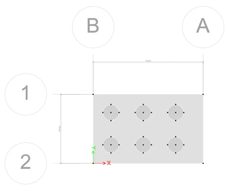
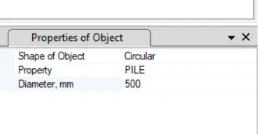
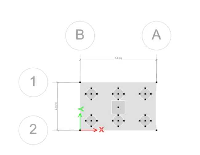
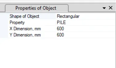
- Now Assign spring on pile
- Click on Assign>joint>spring
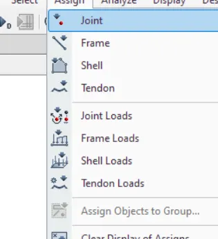
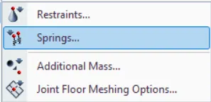
- A dialogue box will appear
- Select the spring and click on ok.
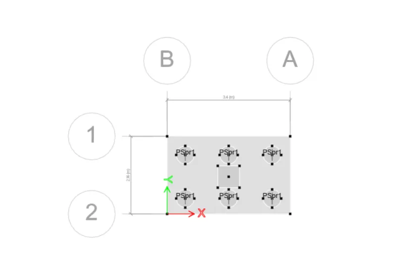
- Assigning joint load on Column
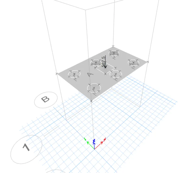
- Click on Assign >joint loads>Force
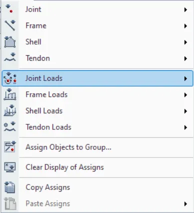
- Joint load assignment dialogue box will appear.
- Enter the value as given in the data i.e.587.5
- Draw the design strip.
- Click on Draw>Design strip
- Then draw using the reference points.
- Run the Analysis.
Click on Analyse>Run analysis.
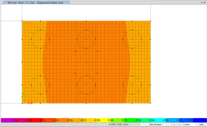
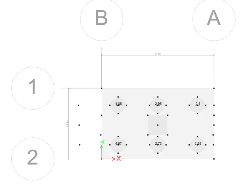
- Check the Result.
- Individual pile capacity under service load
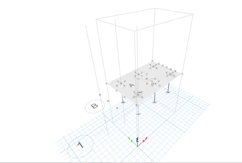
- Two way shear check(punching shear)
- Flexural reinforcement.