Flow Simulation in a Centrifugal Pump
Aim: To simulate the flow inside a geometrically designed centrifugal pump.
Objectives:
- Performing Parametric study for variation of mass flow rate (kg/s) at the outlet and observing the change in pressure values at the inlet and the outlet
- Obtaining the relationship between Pressure ratio (Outlet total pressure/ Inlet total pressure) and mass flow rate
Introduction:
A centrifugal pump is a mechanical device designed to move fluid by means of the transfer of rotational energy from one or more driven rotors, called impellers. Fluid enters the rapidly rotating impeller along its axis and is cast out by centrifugal force along its circumference through the impeller’s vane tips. The action of the impeller increases the fluid’s velocity and pressure and also directs it towards the pump outlet. The pump casing is specially designed to constrict the fluid from the pump inlet, direct it into the impeller, and then slow and control the fluid before discharge. [1]
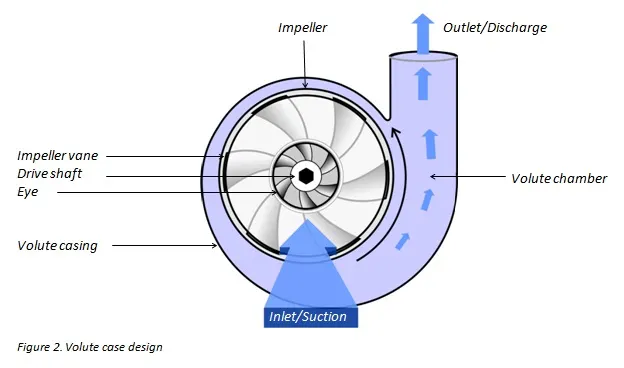
The Main parts of Centrifugal Pump are:
- Impeller: It is a wheel or rotor which is provided with a series of curved blades or vanes. It is mounded on the shaft which is coupled to an external source of energy that imparts the liquid energy to the impeller thereby making it rotate. [2]
- Types of Impellers:
- Open
- Semi-Open
- Closed
- Types of Impellers:
- Casing: The purpose of casing is to translate the fluid flow into a controlled discharge at pressure. In a volute casing, the impeller is offset, effectively creating a curved funnel with an increasing cross-sectional area towards the pump outlet. This design causes the fluid pressure to increase towards the outlet. [1]
- Suction Pipe: It is connected with the inlet of the impeller and the other end is dipped into the sump of water. [2]
- Delivery Pipe: It is a pipe that is connected at its lower end to the outlet of the pump and it delivers the liquid to the required height. [2]
Centrifugal pumps have numerous applications in various industries. They are used often in oil refineries and power plants. They are also the pump of choice for municipal water applications. They are used to move the general water supply from the pressure main in cases where a little or no suction lift is required. They can also be used for boiler feed applications, wastewater management, flood protection, drainage, and irrigation. [3]
Geometry:
|
Front View (Cut-Section): |
Isometric View: |
Fillets are given for ease of transition of fluid and to minimize losses and Lids are created at the inlet and exit to close the flow domain.
Control Volume is the volume used to indicate that the impeller is rotating and not stationary. The rotating component factor for simulations is taken care of by this. The control volume is thus excluded from the parts under analysis. This is done using the component control menu as shown in the figure below.
Problem Specifications:
- Suction pipe Diameter: 88mm
- Impeller Type: Open
- Impeller entry diameter: 90mm
- Impeller exit diameter: 248mm
- Number of vanes/blades: 7
- Type of vanes: Backward curved (Since efficiency is more)
- Speed of the Impeller: 1000 rad/s
- Width of vanes: 12mm
- Casing design: Volute (Varying area from small to large for velocity drop and pressure rise)
- Outlet/Discharge Pipe Diameter: 105mm
- Fluid material: Water
- Density: 1000 kg/m^3
- Viscosity: 8.94e-4 Pa-s
- Fluid cells/mesh: 20,923
- Type of Flow: Steady, Internal
Boundary Conditions:
- Inlet pressure: Environmental (1 atm)
- Outlet Velocity (6 cases): 5,10,15,20,25,30 (m/s)
- Wall: General Boundary Condition by Default
Results:
The results were calculated using 500 iterations for the finishing condition. All other criteria to finish the result were unchecked since they might lead to skewed results as they might stop when the equations are satisfied but not converged.
Goal Table:
Performance curve (Pressure Ratio vs Mass flow rate):
Variation of mass flow rate at outlet:
Pressure contour plots:
Design Point 1: Outlet Velocity = 5 m/s
Design Point 2: Outlet Velocity = 10 m/s
Design Point 3: Outlet Velocity = 15 m/s
Design Point 4: Outlet Velocity = 20 m/s
Design Point 5: Outlet Velocity = 25 m/s
Design Point 6: Outlet Velocity = 30 m/s
Conclusions:
- There is a drop in the outlet pressure with an increase in velocity. This is what is expected as the pressure and velocity are inversely proportional.
- The volute casing helps in reducing the discharge velocity thereby increasing the pressure which is our requirement.
- There is a minimum rise in pressure from inlet to outlet when the velocity is highest (30 m/s) and vice versa.
- From the Performance curve, it can be observed that the Outlet Pressure decreases with an increase in the outlet mass flow rate.
- The mass flow rate at the outlet increases with an increase in the outlet velocity.
References:
- Useful information on centrifugal pumps; Michael Smith Engineers Ltd; https://www.michael-smith-engineers.co.uk/resources/useful-info/centrifugal-pumps
- Centrifugal Pump – Components, Working, Types, and Application; The Constructor; https://theconstructor.org/practical-guide/centrifugal-pump-working-types/2917/
- Best Uses for Centrifugal Pumps; PumpSolutions Australasia; https://pumpsolutions.com.au/best-uses-for-centrifugal-pumps/