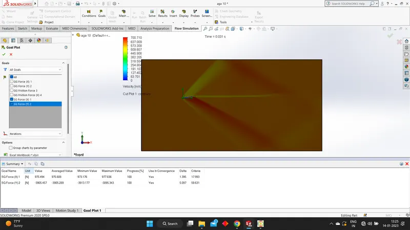
Flow over an airfoil
Aim: To Model the flow over a NACA0017 airfoil.
Theory :
- The NACA airfoils are airfoil shapes for aircraft wingsdeveloped by the National Advisory Committee For Aeronautics (NACA). The shape of the NACA airfoils is explained using a series of digits following the word "NACA". The parameters in the numerical code can be entered into equations to precisely generate the cross-section of the airfoil and calculate its properties.
- Angle of Attack: Angle of attack is the angle between a reference line on a body for an airfoil it is usually the chord line and flow direction of fluid.
- Airfoil: An airfoil is term used to define the waterdrop shape of cross-section of an object like wings,blades,sails that when in flow created an aerodynamic force i.e lift or thrust.
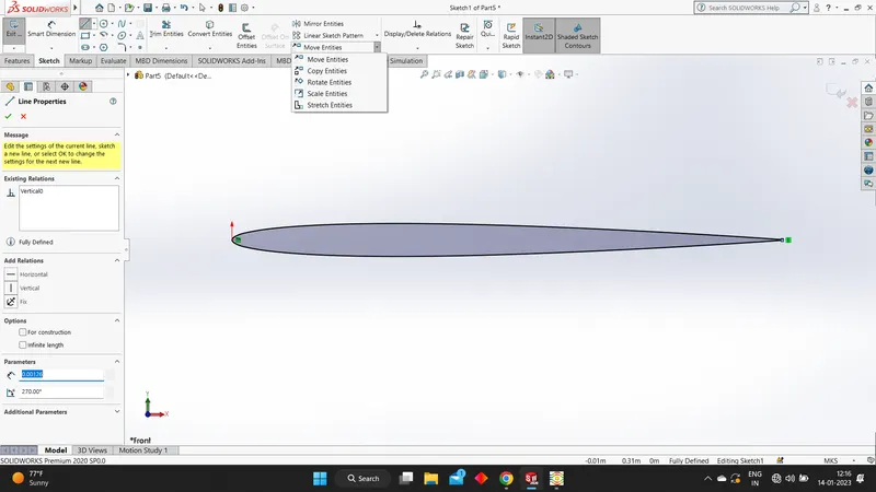
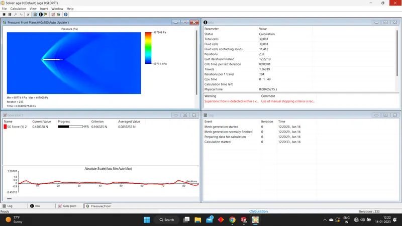
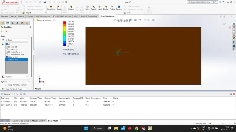
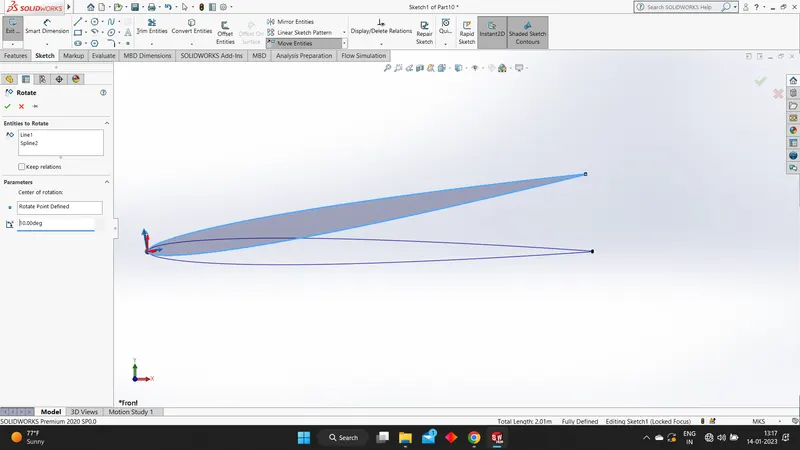
Procedure : Firstly using the insert curves option we draw the outline with given data file then we covert it into an entity and then we apply the varoius angles of attacks (0,2,4,6,8,10) and then we extrude it . Using the wizard tool we insert the project name everything is set to default except for a few conditions , its an external flow then time dependant we need a result every 1 second for 5 seconds, then we change the velocity in the x direction to 600m/s. Using the computational domain we set it to 2D and then fit it in , then we insert the various goals like the global goals ( forces in X and Y directions only) then surface goal (the top surface and forces in X&Y directions only). Then we define the basic mesh later we insert a local mesh then we run it , after getting the results we create a cut plot and choose the velocity parameter. Then we insert the goal plot to get the drag force that is the integrated force along x axis and the lift force that is the integrated force along y axis.
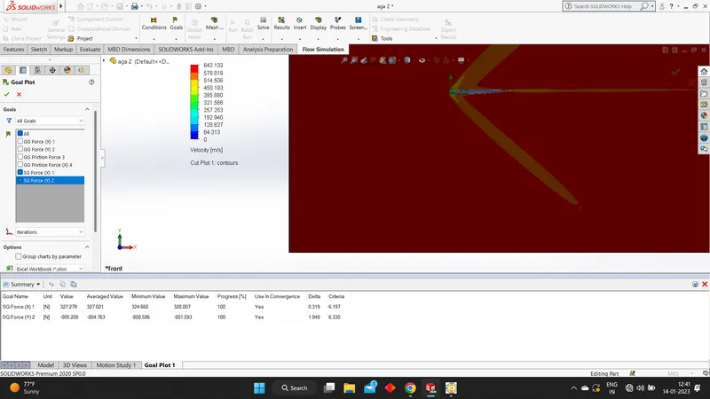
Conclusion: From these plots attached we can understand that, It can be seen that as Angle of Attack increases the Lift Forces and Drag Forces increases.The increase in Drag force is gradual while increase in Lift Force is with much greater slope.
below i shall attach the necessary pictures , links
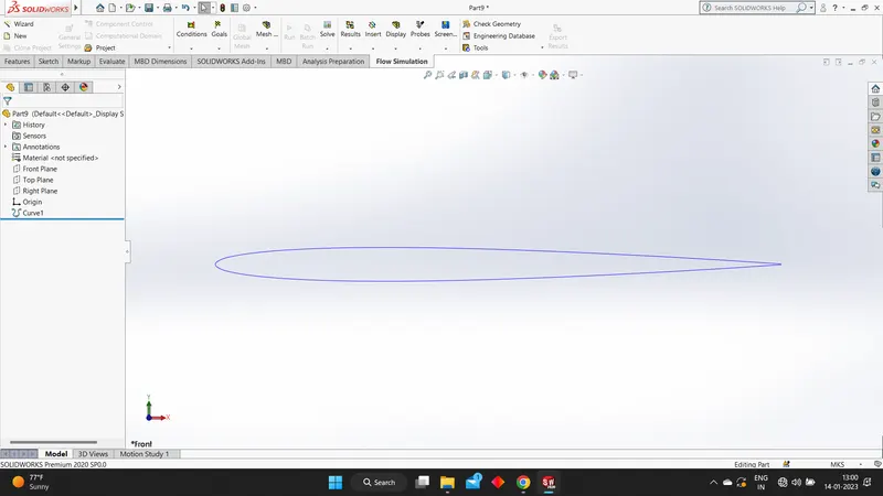
The outline we get when use the data given
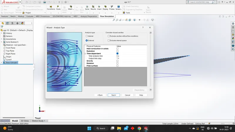
Then we need to modify a few conditions in the wizard :
External and time dependant
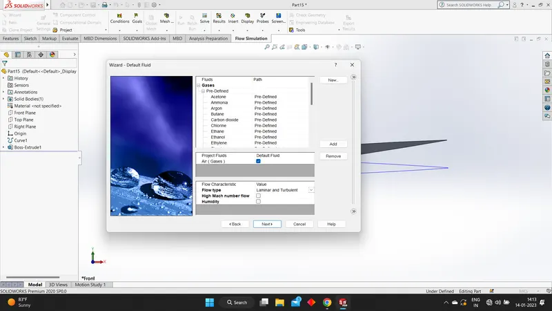
Choosing air
Changing velocity in x-direction
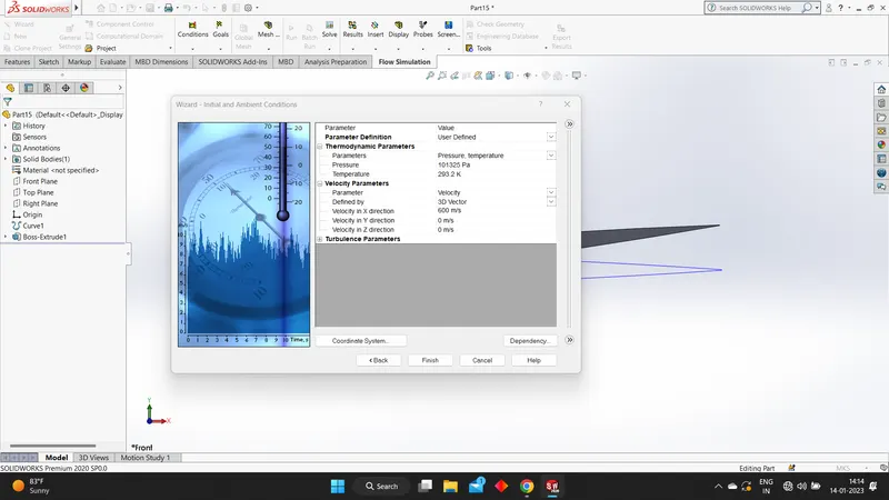
Adding the computational domain , the goals and the local mesh
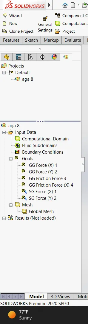
When angle of attack is 0:
Outline we get from the data
Using rotate option we give the angle of attack
The results after the run
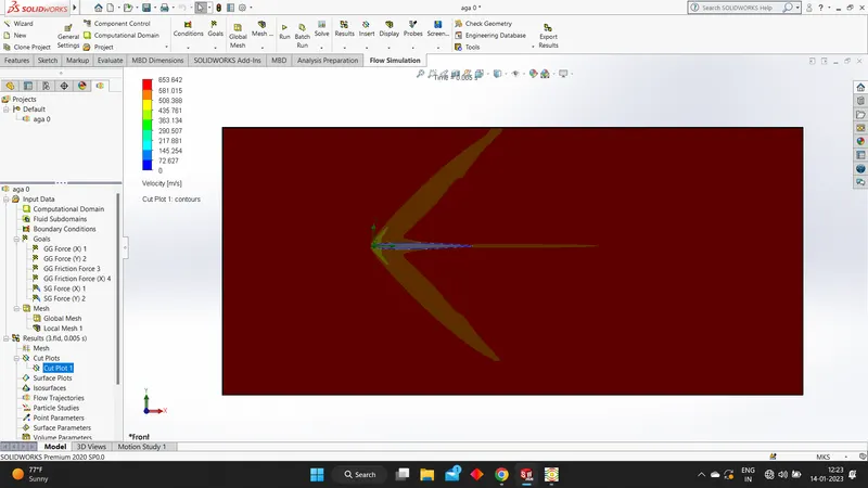
Velocity contours
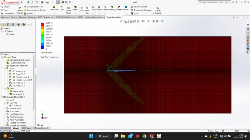
Velocity contours without mesh
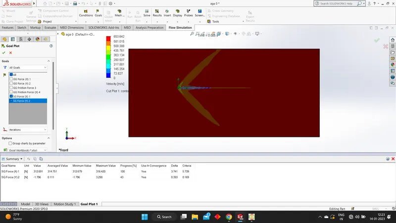
Final data
When angle of attack is 2:
Outline we get from the data
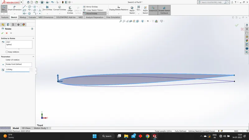
Using rotate option we give the angle of attack
The results after the run
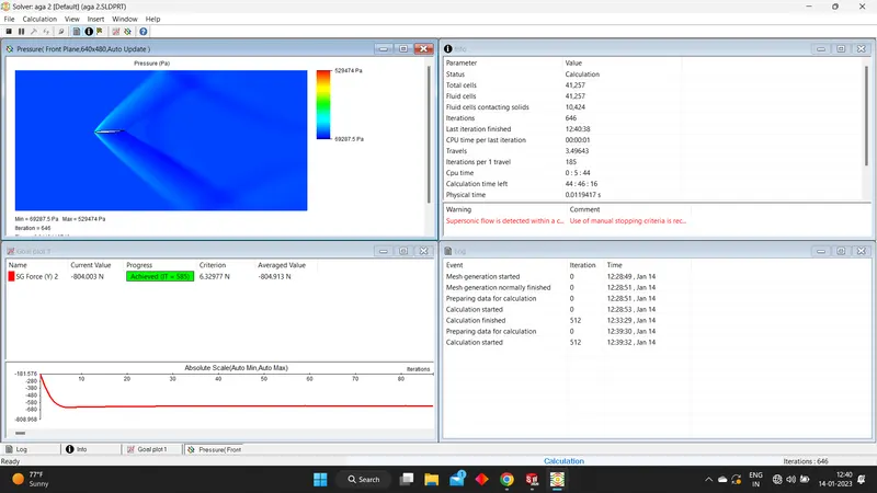
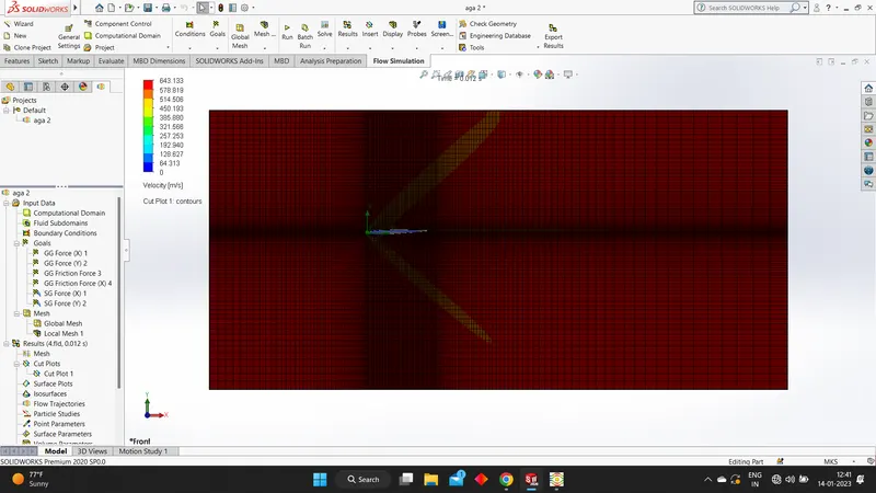
Velocity contours
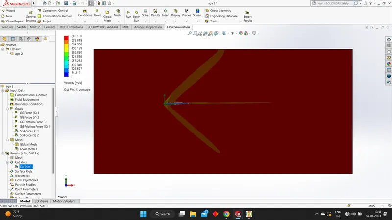
Velocity contours without mesh
Final data
When angle of attack is 4:
Outline we get from the data
Using rotate option we give the angle of attack
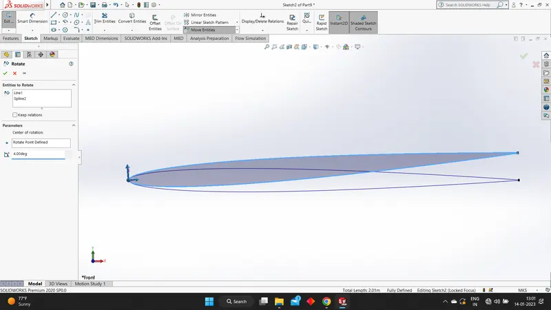
The results after the run
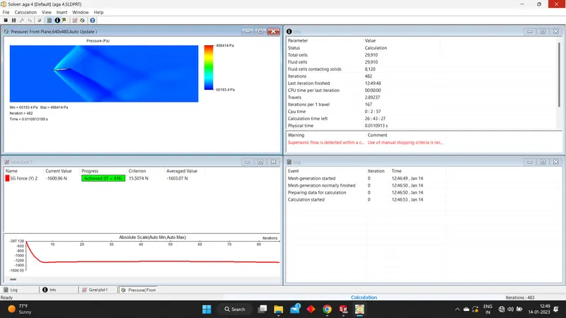
Velocity contours
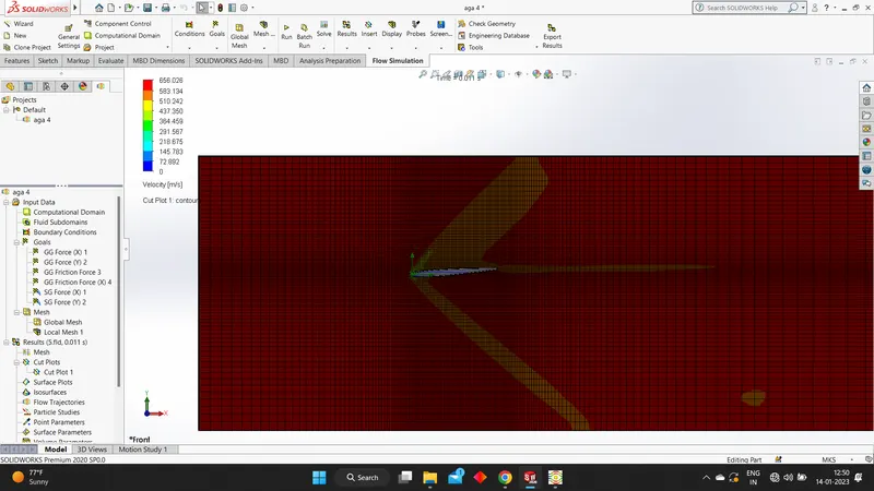
Velocity contours without mesh
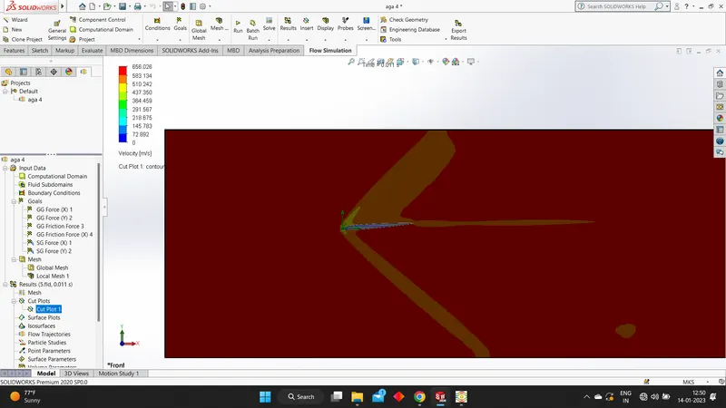
Final data
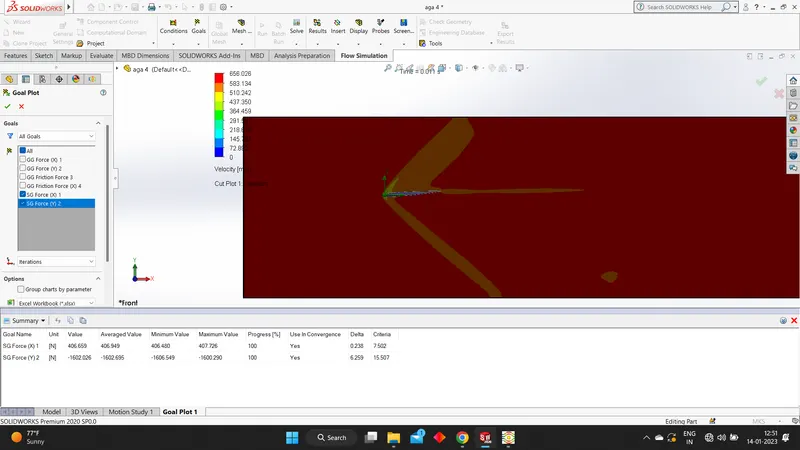
When angle of attack is 6:
Outline we get from the data
Using rotate option we give the angle of attack
The results after the run
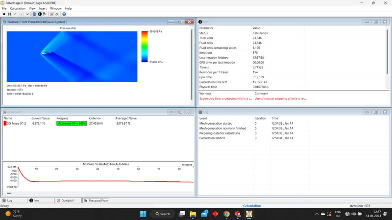
Velocity contours
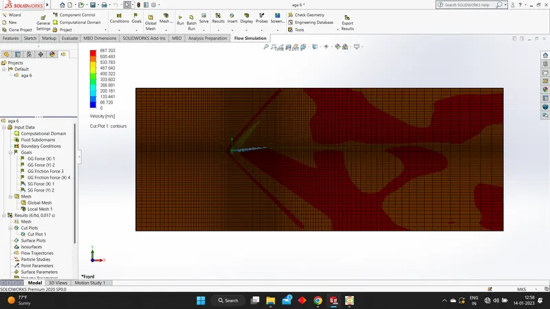
Velocity contours without mesh
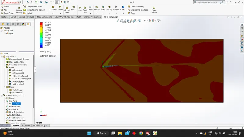
Final data
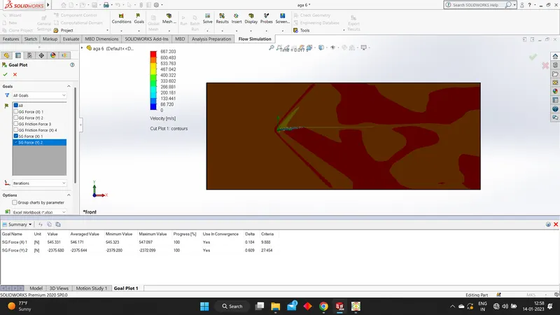
When angle of attack is 8:
Outline we get from the data
Using rotate option we give the angle of attack
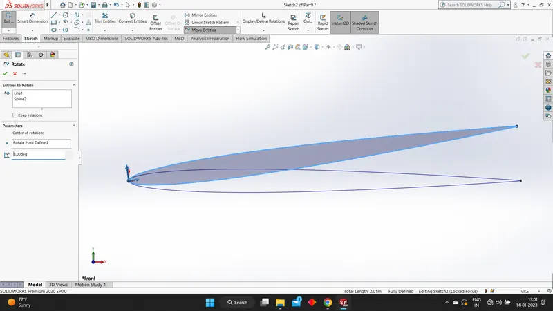
The results after the run
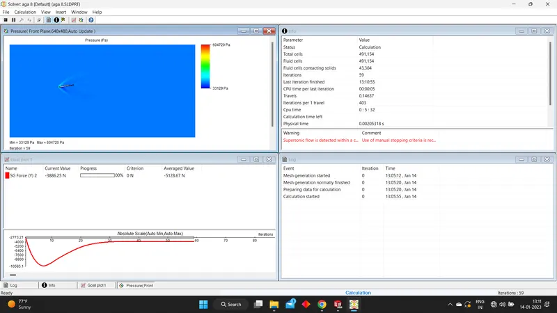
Velocity contours
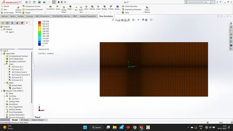
Velocity contours without mesh
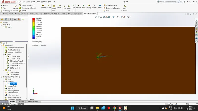
Final data
When angle of attack is 10:
Outline we get from the data
Using rotate option we give the angle of attack
The results after the run
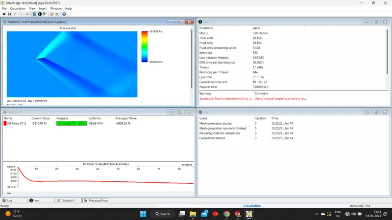
Velocity contours
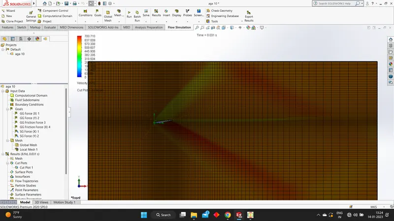
Velocity contours without mesh
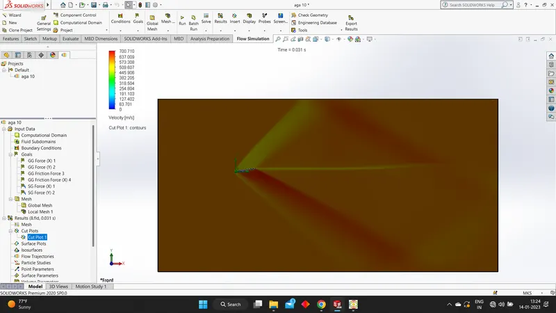
Final data