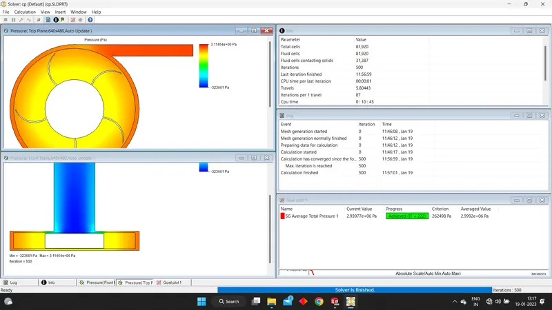
Centrifugal pump design and analysis
Aim:
To model a centrifugal pump and perform a Parametric Simulation at different outlet velocities to obtain relationship between Pressure Ratio and mass flow rate.
Theory:
A Centrifugal pump is a mechanical device designed to move a fluid by means of transfer of rotational energy of one or more driven rotors called impellers to kinetic energy which makes the fluid flow.
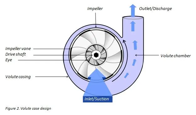
There are different types of Centrifugal Pumps:
A)Type of flow:
1)Axial Flow
2)Radial Flow
3)Mixed Flow
B)Number of Stages:
1)Single Stage
2) MultiStage
C)Closure of impeller:
1) Open
2) Semi-Open
3) Closed
D)Type of impeller:
1)Forward Swept
2)Radial Exit
3)Backswept
E)Type of casing:
1)Volute
2)Diffuser
Procedure :
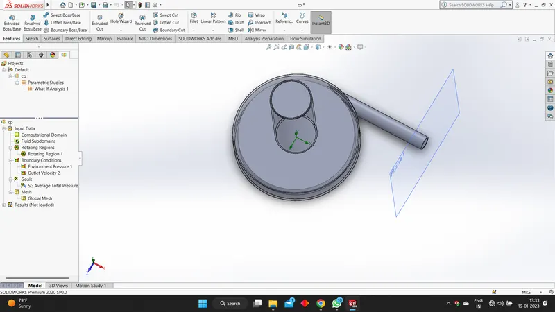
Firstly we draw the circles and the blades to make the impeller first and then next we make the volute or outer casing and then while doing there is an important step we have to check is while extruding we have to check the merge results option we have to untick it, then we draw the inlet runner , then we draw the exit length with this we will complete the volute. Then we create shells followed by the casing for the blades and then we save it. Now we will use the wizard to create a new project , all the options are set to default except that we will be using the rotation option, then we will use water as the liquid since we're interested in simulating it . And then we create lids and then we select the components which we don't want in our study and we insert rotation region and then we give the boundary conditions for the inlet and the outlet , and then we can run it before running we need to check the calculate control option and unmark few things and increase the iterations to 500. Then we check the results and use flow trajectories to create it and then when we play it we can understand how the flow takes place and then we create a new parametric study and then give the input the output velocity and then provide the starting and ending values and the number of values and then we define the output parameter i.e. is the total pressure , and then we get the different scenarios and then we run the study and get results.
Conclusion:
With the increase in outlet velocity of pump the mass flow rate also increases proportionally. The Performance Diagram of Pressure Ratio vs Mass Flow Rate can help us understand Performance of Pump for different Pressures.
below i shall attach the followins screenshots, animation, links , files.
The centrifugal pump.
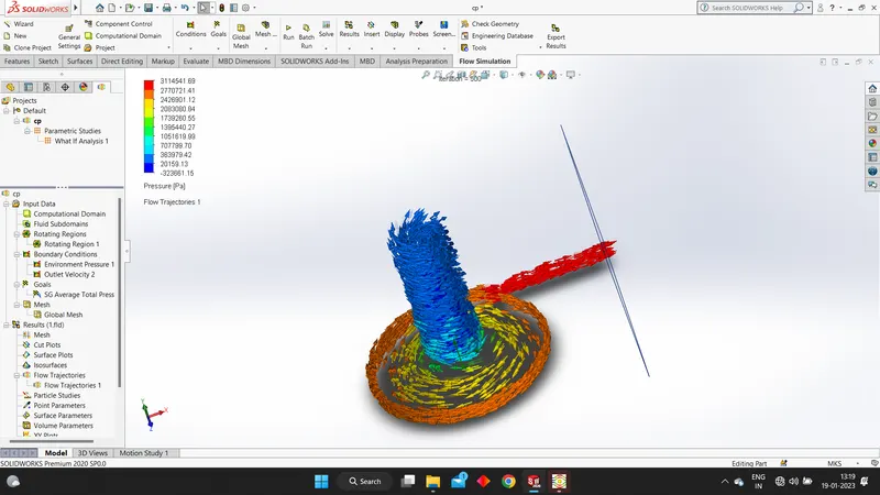
These are the results we get after running the simulation.
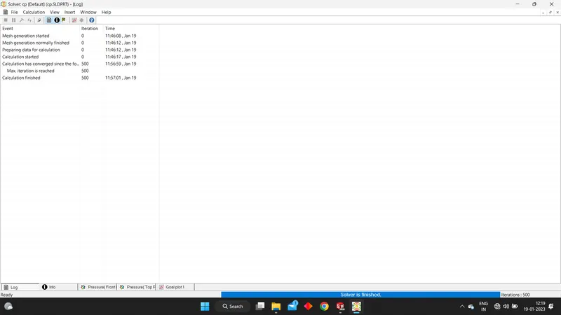
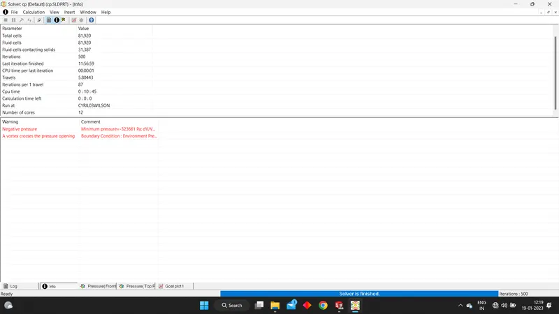
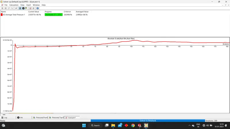
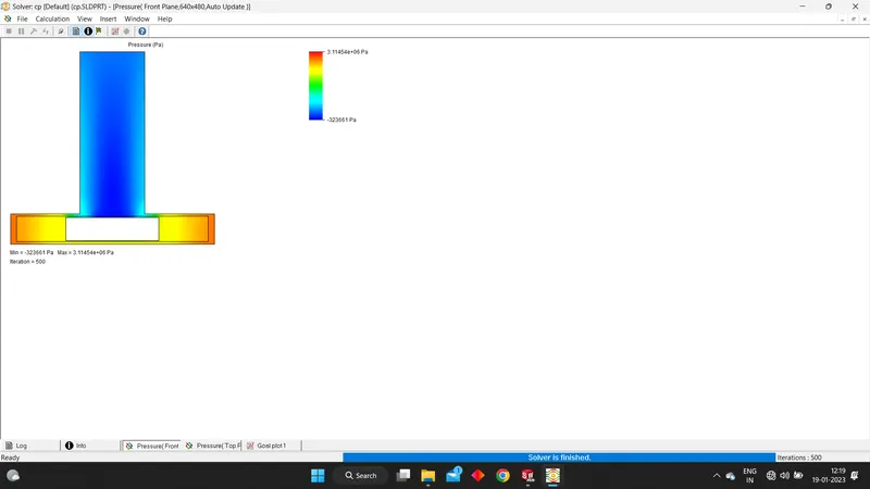
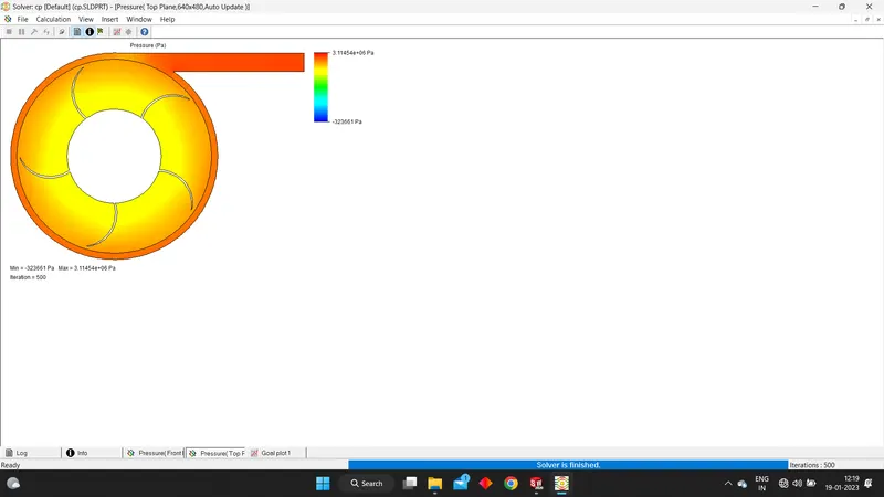
The trajectory
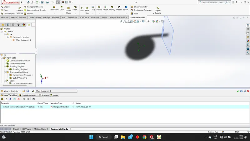
Then we create a parametric analysis and run it and get the following results,
The input
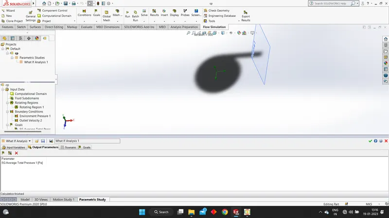
The output parameters
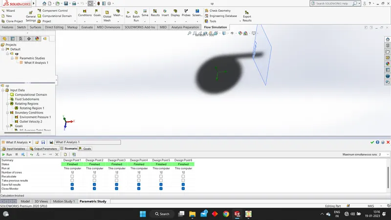
The scenarios
The goals
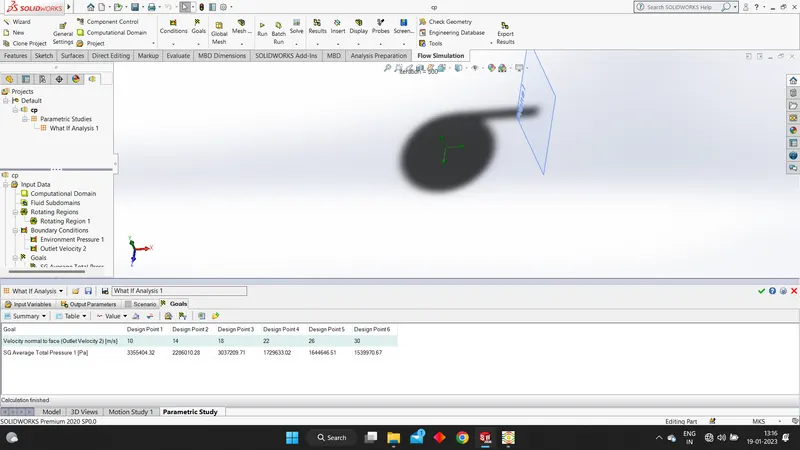
The combined picture of the result