FINAL TEST
PFI ENGINE
Q1. What is the Compression ratio for the engine?
The compression ratio is defined as the ratio between the cylinder and the combustion chamber of the internal combustion engine at its maximum and the minimum volume
Mathematically, it can be represented as follows
Compressionratio=VolB.D.CVolT.D.C=Vd+VcVcCompressionratio=VolB.D.CVolT.D.C=Vd+VcVc
where,
VolB.D.CVolB.D.C is the volume of the cylinder at bottom dead center
VolT.D.CVolT.D.C is the volume of the cylinder at top dead center
VdVd is the Displacement / Swept Volume
VcVc is the Clearance volume
For internal combustion engine, a high compression ratio is favorable because of higher thermal effciency of the system. As a result, the internal combustion engine can reach high combustion temperature which provides more work output for the same amount of fuel. This is because the IC engine is conceptually based on the heat engine and as a result, longer expansion cycle provide more work output and less heat wasted to the surrroundings in the form of exhaust.
Q2. Modify the compression ratio for this engine to 10.3 without changing geometrical parameters?
There are two possible ways of increasing the compression ratio of the engine without changing the geometrical parameters of the engine. They are as follows:
- Changing the clearance volume
- Changing the swept volume
The maximum and the minimum volumes for the PFI engine is as follows:
Vmax=5.74×10⁻⁴m3Vmax=5.74×10⁻⁴m3 and Vmin=5.70×10⁻⁵m3Vmin=5.70×10⁻⁵m3.
Using the above definition of the compression ratio, we can calcualte the value of displacement and clearance volume
Vc=VminVc=Vmin and Vd=Vmax−VcVd=Vmax-Vc
Substituting the above values for the maximum and the minimum volume we get,
Vc=5.70×10⁻⁵m3andVd=5.17×10⁻⁴m3Vc=5.70×10⁻⁵m3andVd=5.17×10⁻⁴m3
Let us the first technique to reach our target compression ratio
10.3=5.17×10⁻⁴+VcVc10.3=5.17×10⁻⁴+VcVc
Vc=5.56×10⁻⁵m3Vc=5.56×10⁻⁵m3
Let us the second technique to reach our target compression ratio
10.3=Vd+5.7×10−55.7×10−510.3=Vd+5.7×10-55.7×10-5
Vd=5.301×10⁻⁴m3Vd=5.301×10⁻⁴m3
Q3. Calculate Volumetric Efficiency for this engine?
Volumetric efficiency is a ratio of the mass of the air and fuel trapped in the cylinder during the induction stroke and the mass that would occupy the displaced volume if the air density in the cylinder were equal to the ambient air density. Alternatively it can be represnted as ratio of the mass of air volume drawn into the cylinder to the cylinder's swept volume.
We can express the second definition mathematically as follows
ηv=VaVdηv=VaVd
The air sucked into the cylinder during the intake stroke can be calculated using the ideal gas assumption
Va=mRTPVa=mRTP
where,
P = Atmospheric pressure conditions = 101325 Pa
T = Temperature of the air at atmospheric conditions = 293 K
R = Universal gas constant = 287 J/kgK
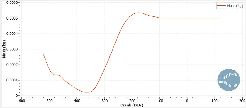
m = Mass of air = 0.00050051627 kg
Substituting the values of P, m, R and T in the ideal gas equation, we get,
Va=4.4317×10⁻⁴m3Va=4.4317×10⁻⁴m3
Therefore, volumetric efficiency for this engine is
ηv=4.4317×10−45.17×10−4×100=85.72%ηv=4.4317×10-45.17×10-4×100=85.72%
Q4. Measure the air mass flow rate for this engine in kg/s?
The mass flow rate is defined as the ratio of the amount of air entering into the engine cylinder per unit time. From the above line plot, we know that the steady amount of air entering into the engine cylinder for one cycle
ma=0.000534kgma=0.000534kg
The speed of the engine is 3000RPM3000RPM. By conversion into seconds, we get that the speed of the engine is 50RPS50RPS
Therefore, air mass flow rate for the is engine is = ma×N=0.000534×50=0.0267kgsma×N=0.000534×50=0.0267kgs
Q5.Why is the cell count varying during the simulation?
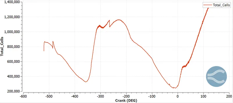
In addition with the base grid, for capturing the combustion and flow physics accuractely we have added fixed embedding near the spark ignition source and the spray nozzle and also volume embedding inside the cylinder region of the engine. Simulatenously, the flow near the valves is also captured accurately because of the boudnary embedding. Also, adaptive mesh refinement in the combustion chamber for resolving sub grid scale velocity and temperature has been implemented in the current simulation. As a result, the number of cells keep varying during the simulation
Q6. In a real engine, valves are in contact with the cylinder head but while running simulation, there is a small gap?
a) The central concept behind CONVERGE surface formation is that the edge of the triangles which constitutes the surface can be shared only by two traingles. If more triangles share the same edge, it will lead to non-manifold errors. As a result, a small gap is present in the simualtion to separate the intake port and the cylinder region and the solver itself addes the disconnect triangles during the simulation to stop the flow of the fuel + air mixture from the intake to the cylinder region
b) If the gap is big which can happen because of improper boudnary flagging the disconnect triangles that seperate the region will overpredict the separation of the regions which will result into lower amount of mass air + fuel entering in the cylinder. Consequently, the results of the simulations will be less accurate and not reliable.
Q7. How many seconds does combustion last in this case?
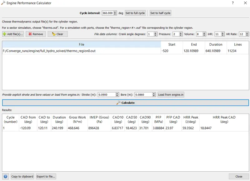
From the engine performance calculator avaliable in the CONVERGE Studio, we observe that the combustion starts from -120.09 deg to 120.11 deg. The total duration of the combsution in the crank angle form is 240.199 deg. We know that, the speed of the engine is 18000 deg/s. Therefore the duration of the combustion in seconds is as follows
t=240.19918000=0.01333st=240.19918000=0.01333s
DIESEL ENGINE
Q1. What is an advantage of SECTOR Simulation?
Since, the engine cylinder is axisymmetric, we can exploit these symmetries during the simualtion by providing appropriate symmetry and perodic boundary conditions. The major benefit of doing so is reduced use of computational resources and smaller simulation time without lossing any accuracy in the simulation. As a result, CONVERGE provides built in support for making engine sector surface to speed up the close cycle analysis work flow.
Q2. When will the sector approach not work?
The sector approach will not be useful when we interested in the open cycle analysis or in a multi injector system. This is because the assumptions of close cycle analysis such as the stationary valves do not hold for the open cycle analysis and the motion of the valves is needed to be modelled which cannot be done in sector approach. In multi injector system, the symmtery of the injectors nozzle around the center of engine's cylinder will not hold.
Q3 How to choose Start Crank Angle (SCA) and End Crank Angle (ECA) for a sector simulation?
As we know, that the sector simulation is based on the close cycle assumptions, so the analysis is only valid at the beginning of the compression stroke and ends at the completion of the expansion stroke. For instance if the fuel inkection takes place at 0 CAD then the compression stroke starts from 180 CAD and is valid till the end of the expansion stroke at 540 CAD.
Q4. Can we convert the PFI case into a SECTOR case? Explain your answer?
For the PFI engine the injection of the fuel is outside of the engine's cylinder. Even if we manage to provide an approximate boundary condition for injection it will not be symmetric. Furthemore, our interest in PFI Engine simulation was for open cycle analysis but the sector simulation will limit the scope of our simulation only till the closed cycle of the PFI engine. Apart from this, the modelling of the spark plug in a will pose a significant challenge. From these reasons we can conclude that PFI Engine cannot be converted into a SECTOR case.