Final Project: Electric Rickshaw modelling
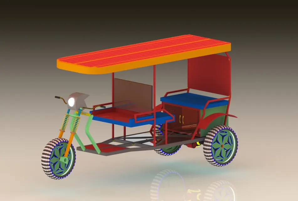
Create a detailed MATLAB model of an electric rickshaw (three wheel passenger vehicle) as per details below:
Rear wheels driven by PM brushed type motor
Assume efficiency points of motor controller and motor
Make an excel sheet of all input and assumed data
Results: For any three standard driving cycles show energy consumption, temperature rise of motor and controller for 100 km constant speed driving at 45 kmph.
(Note- The simulink model file should be compulsorily attached)
Ans:So, here we need to design the electric auto rickshaw(3 wheel passenger vehicle)
BLOCK DIAGRAM:
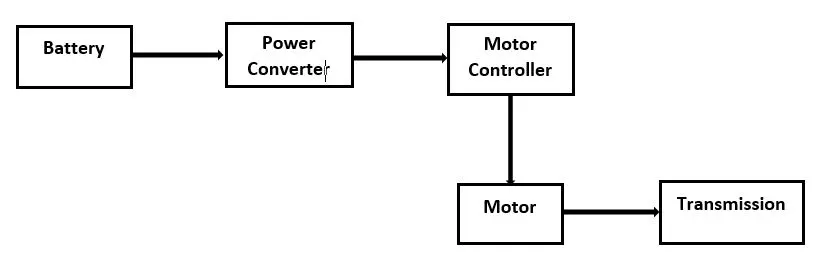
Electrical Riskshaw mode:-

The main Blocks used in the models are:
- Drive Cycle.
- Driver .
- Power converter sytsem.
- battery system.
- Motor and transmission.
- Vehicle dynamics.
- Distance calculater.
System Level Modeling:-
1)Vehicle Dynamics:
a)Wheels-
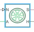
i)The vehicle consist of 3 wheels ,and Rear wheel driven.
ii)The wheels are modelled using simple Tire (Magic formula) simulink blocks.
iii)the tire consist of N,A,H,S ports .
iv) The N ports is for the Normal Reaction acting on the tire.
v)The A port corresponds to the Mechanical Rotational conserving port for the wheel axle,so we should connect the same axle tires with each other.
vi)S port is for the Slip
vii)H port is the wheel hub through which the thrust developed by the tire is applied to the vehicle.So we need to connect the gears with the H port.
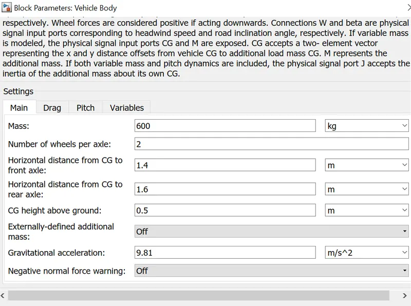
b)Body-
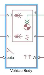
The vehicle body block in the name suggest it holds all the components of the vehicle which needs to be mounted on it.
The block accounts for - body mass,aerodynamic drag,road incline,weight distribution between axles due to accelerationroad profile.
Vehicle body substem:-
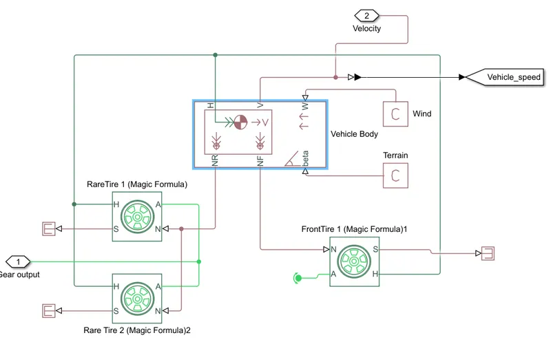
- The Rikshaw is rear wheel drive and have 3 wheels.
- The rear wheels are connedcted to NR port.
- NF is connected ti the front wheel.
- H is connected to the tire Hub.
2)Motor and Transmission:-
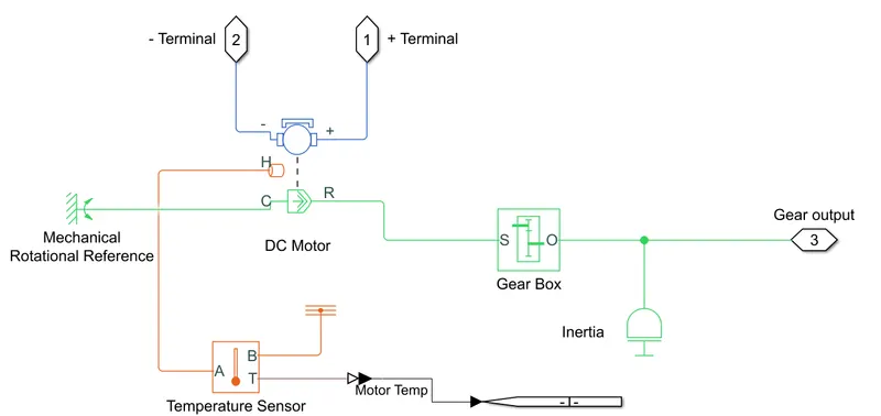
This is the subsystem for the motor and the transmission.
we have taken a Dc motor and the gear box accordingly.
a)Motor-
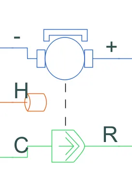
- In this model we have used the DC motor as it is the most simple motor to use and control.
- The bule part of the motor block is electrical and the Green part is the mechincal .
- The motor is Parmanent magnet DC type.
- H is the heat given out by the motor,as in the model we need to identify the rise in the temperature of the motor.
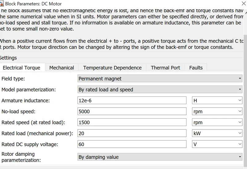
To sense the temperature of the motor an temperature sensor block is ussed.
b)Gear box-
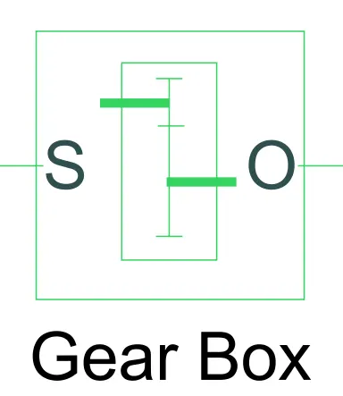
- Here we have considered the simple gear box with the gear ratio to be 5.
- From the gear box the output is directly given to the axis of the wheels.
- Represents a fixed-ratio gear or gear box. No inertia or compliance is modeled in this block. You can optionally include gear meshing and viscous bearing losses.
- B (base) and F (follower) are mechanical rotational conserving ports.
- Output shaft rotates in in same direction of input shaft.
c)
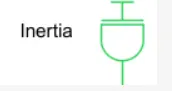
Inertia 0.01 kgm^2. The block is ideal mechanical rotational inertia.The block has one mechanical rotational conserving port. The block positive direction is from its port to the reference point. This means that the inertia torque is positive if the inertia is accelerated in the positive direction.
3)Motor Controller:
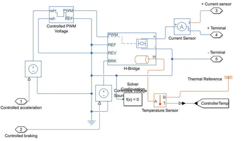
a)H-bridge-
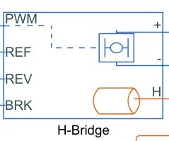
PWM-Input pulse is given to this port with the help of Controlled PWM volatge Block.
H-bridge can operate in PWM and Average mode.
REF: The port is for the reference input.The refernece input is connected to the ground.
REV:The port is used for the reverce motion of the motor ,but for this model use connect the REV with the REF port as we do not consider the backward motion of the vehicle.
BRK:This port is used for braking and the regenerative braking so when ever the vehicle speed reduces or deaccelerate the electrical power will be feed to the battery and the battery will get charge.
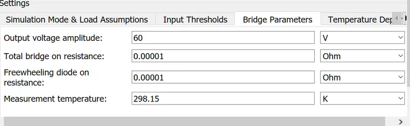
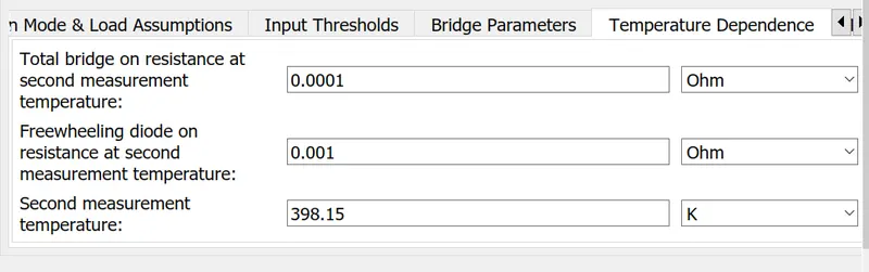
H-Bridge:(DC-DC Controller)
To get the desired controlled DC volatge we have used a H-bridge controller,as it can operate in all 4-Quadrant.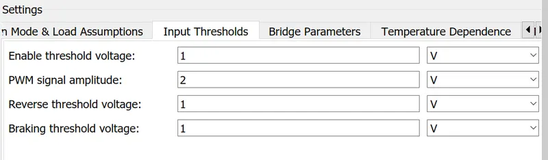
The thresholds are as above image.
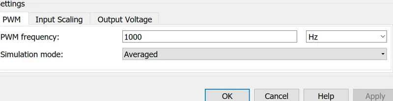
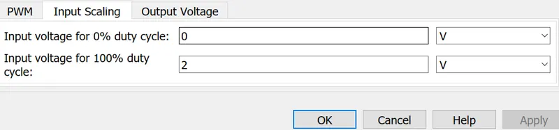
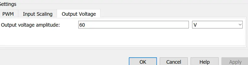
b)controlled PWM voltage-
To get output from the H-bride we have to give the input to the PWM ,so this input pulse is generated using controlled PWM volatge block.
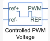
The inputs ports is takens as the acceleration given by the driver,block generates corresponding pulse width as per the accelerations and brakes apllied by the driver himself.
The PWM and the REF ports are given to the H-bridge as the inputs.
4)Drive cycles:-
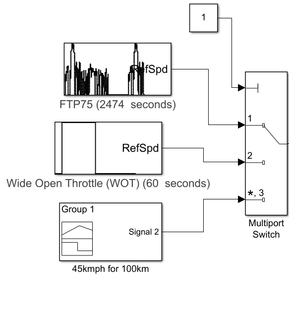
In the model we are using 3 drive cycles connecd to the multiple port selector switch.
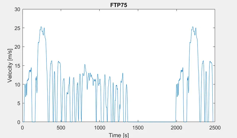
1)FTP75(2474)
2)wide open Throttle(WOT)
3) Manually prepared drive cycle(100 km constant speed driving at 45 kmph.)4
- The drive cycle is the input given to the vehicle,as the drive cycle will represent the pattern of driving style in which a real driver will drive a vehicle.
1)FTP75:-
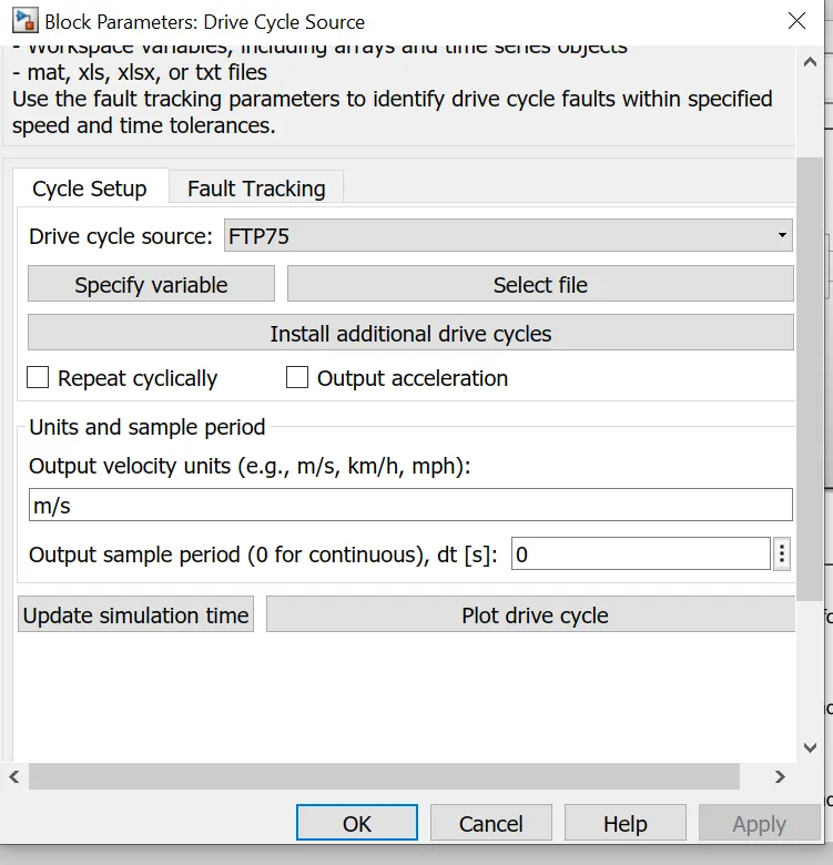
Wide open Throttle(WOT):-
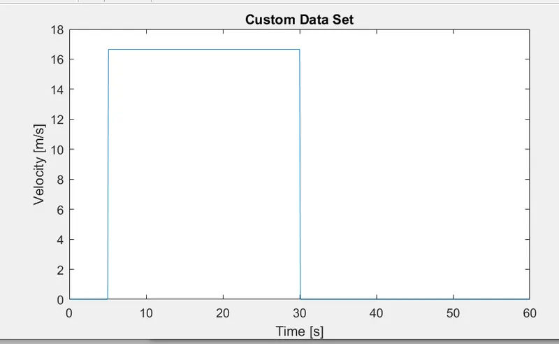
manually prepared drive cycle(for 12.5m/s speed):-
Here the 45 kmph speed is converted into meter per secons,and is constaly given for 8000 seconds.
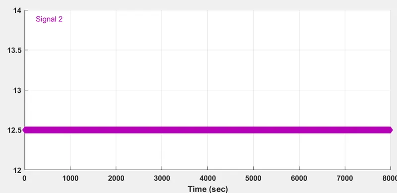
All three drive cycles are controlled by the controller provided above by constant through multi-port switch.
2)Driver:-
- Here we are using a PID controller to get the controlled output ,the reference speed and the vehicle speed is given to the PID to get the best posible controlled output.
- For the acceleration an deacceleration we are using 2 saturation which will ensure the proper braking an acceleration of the vehicle.
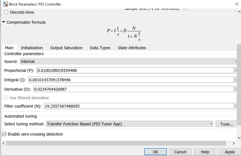
- So here we need to tune the PID the correct way to get the response of the sytsem faster.
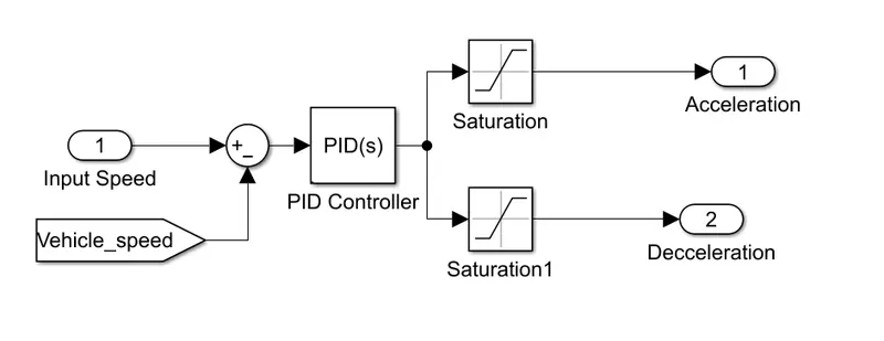
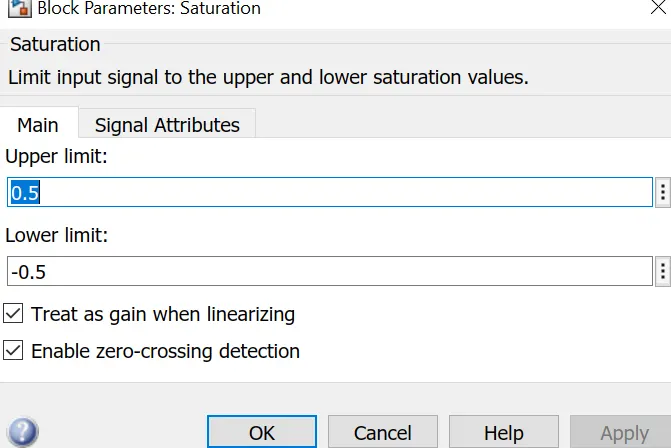
PID Controller:We have adjusted the PID values.Shown in below image
6)Battery System:-
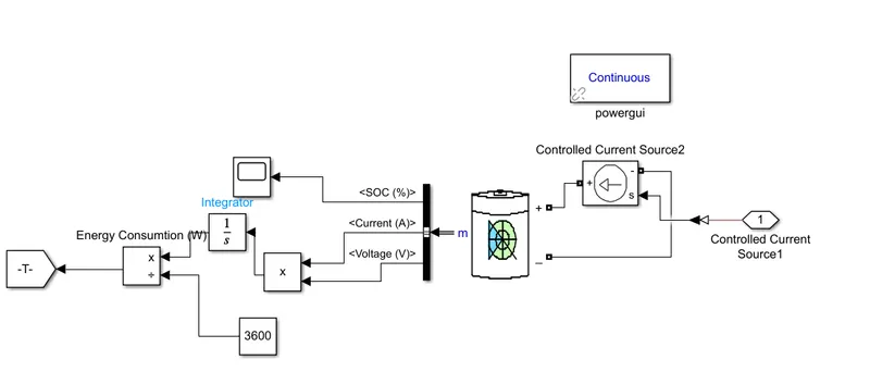
The electrical rikshaw will gets it power from this battey system,and during the regenerative braking this battery will get charged.
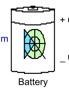
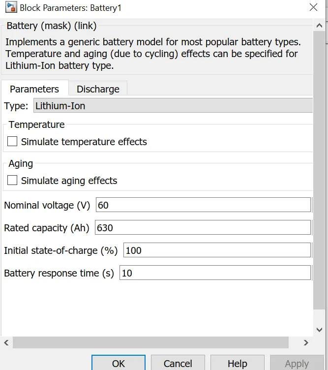
- This battery is a lithium-ion type of a battery.
- The nominal voltage is 60v
- Rated capacity is 630(Ah)
- In the intial condition we are considering the SOC to be 100% charge.
7)SOC of the battery:-
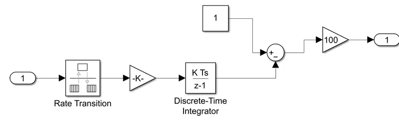
- This subsystem block is used to calculate the SOC of the battery.
- Initialy we consider 100 % of battery charge.
- ZOH block (zero order hold)is used to sample the input signal.
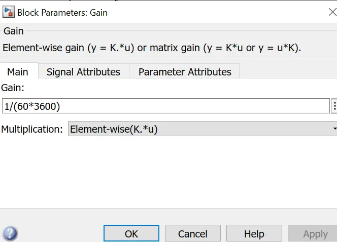
- Gain(K)=1/(60*3600)
- 60 is the volatge and 3600 is the time.
8)Distance calculation:-
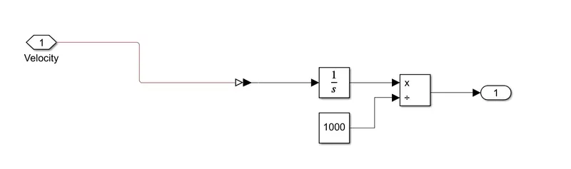
- The velocity is given as the input to this subsystem and then the input is integrated and converted into distance and we can display the distance travel on the display.
RESULT:-
For FTP75 Drive cycle:(Multiport constant=1)
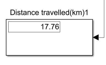
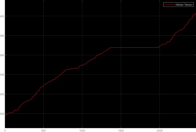
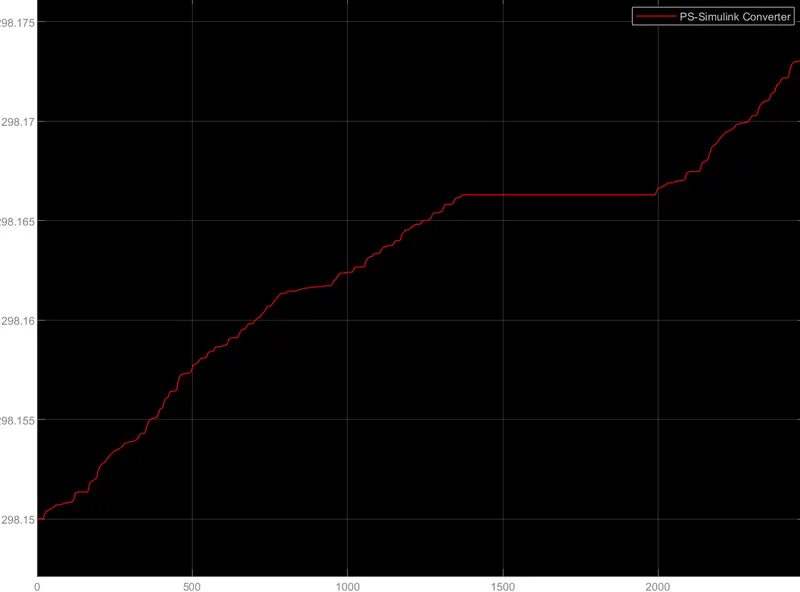
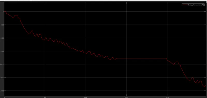
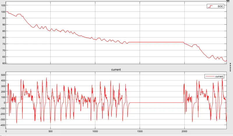
For the FTP drive cycle the vehcile will travel the distance of 17.76 km with run time of 2474sec.
MOTOR TEMPERATURE>
CONVERTER TEMPERATURE>
Energy consumtion(W):
SOC>
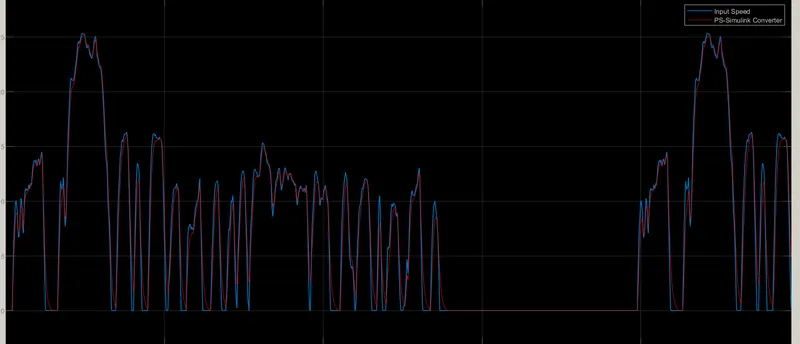
- The actual Speed is following the reference Drive cycle.
- The SoC% of the battery is reduced to 62 %.
- The Temperature of Motor is increased to 420C.
- The Temperature of Controller is 298.174C.
- From the batery SOC we can see when the regenberative barking is taking place.When ever the SOC is increasing then we can say the battery is charging.
FOR WOT drive cycle:-(Multiport constant=2)
CONTROLLER TEMPERATURE>
MOTOR TEMPERATURE>
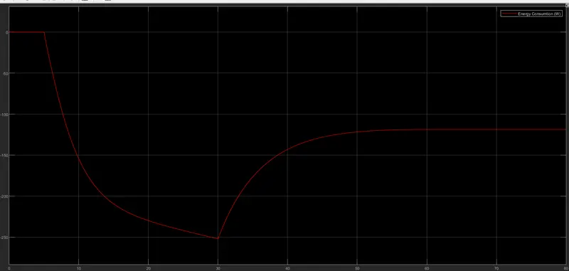
ENERGY CONSUMPTION>
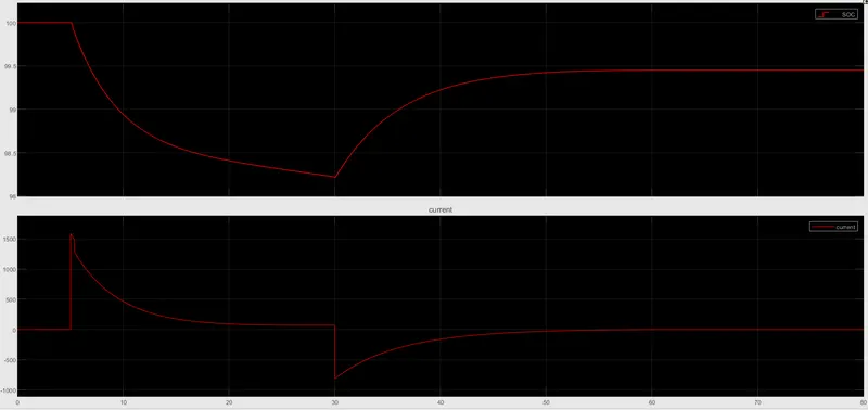
SOC & CURRENT>
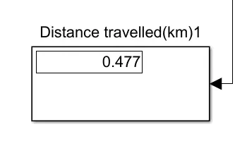
- The vehicle have covered a distance of 0.477km.Run time is 80secs.
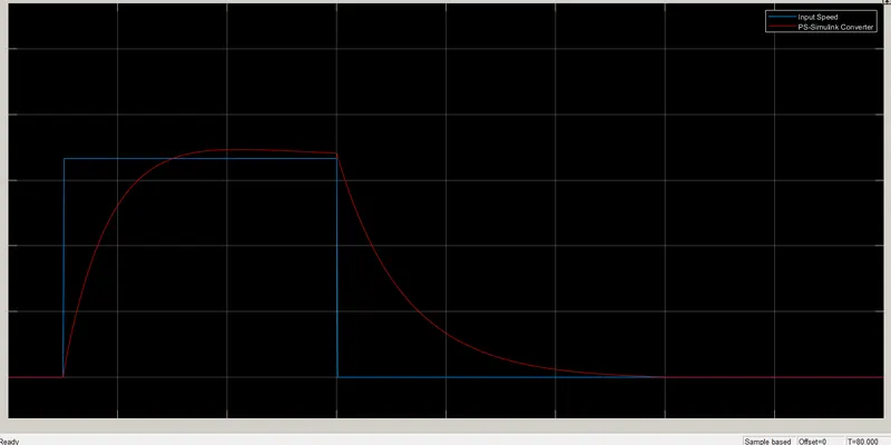
- In WOT drive cycle the vehicle actual speed will find it difficult to follow the
- Energy consumed by the battery is increased linearly till 250 approx. Then again reduced to 120 gradually due to back EMF and finally at the end of the cycle.
- The SoC% of the battery is reduced to 99.4% at the end of the drice cycle.
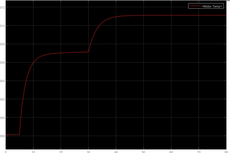
- The Temperature of Motor is increased suddenly to 311°.
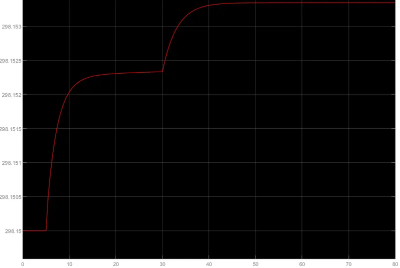
- The Temperature of Controller is 298.15°C.
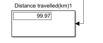
Now for the 45kmph for 100kms drive cycle:-(Multiport constant=3)
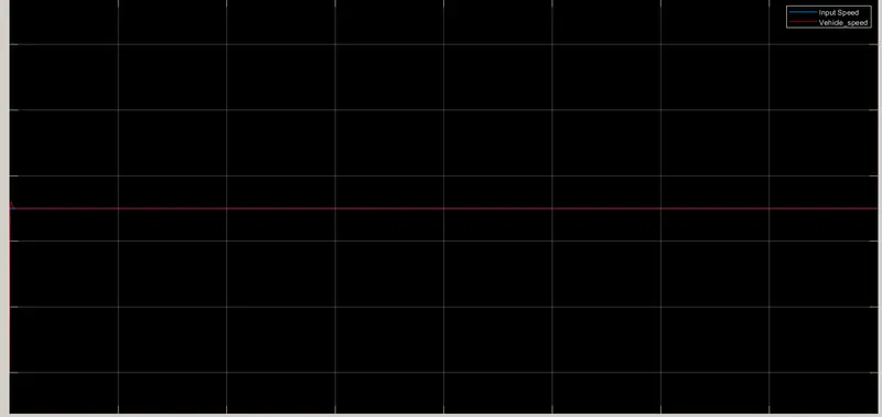
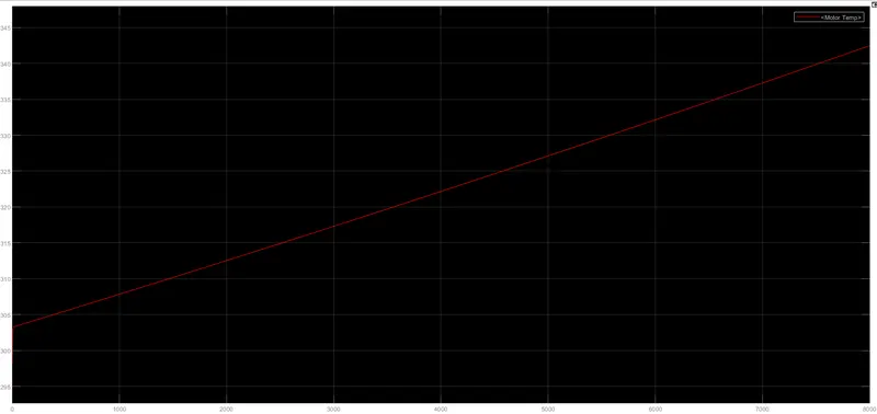
MOTOR TEMPERATURE>
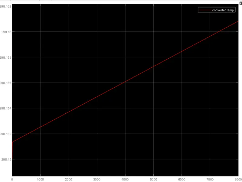
CONTROLLER TEMP>
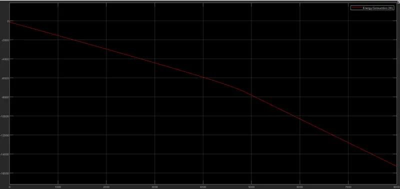
ENERGY CONSUMPTION>
SOC & CURRENT>
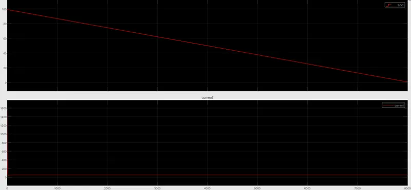
- In the drive cycle the vheicle speed is constant for 8000 secs,so that vehicle can reach 100kms.
- The actual speed of the vehicle follow the reference speed aproximately 99%.
- The vehicle is constant in it speed so now the motor and the controller will get heated with a constant value,and as there is no braking or decrease in the speed there is no regenerative braking so the battery will never get charge for the full drive cycle.
- The motor and the controller is 342 C and 296.16C.
- The consumption is 14.5KW.
- The SOC is 5% at the end of the drive cycle.
Conclusion:
Thus we haves succesfully done the simulation for the 3 drive cycle using DC motor . Understand and analysed the results of the simulation.
Use of different type of simulink blocks.
We have seen how to model 3 wheels EV and carry out a real time simulation and how a motor controller works and what role it plays in the control of the electric and succesfully .
We have seen how the temperature increase in motor and the controller.
calculate the SOC of the battery and seen how the energy is consumed.