Final Project: Electric Rickshaw modelling
Aim:
To model the Electric Rickshaw (ERsh) using Matlab Simulik
To estimate the SoC using Amper hour Method
To Calculate the distance travelled by the Cat in specific time.
Fundamentals of ERSh:
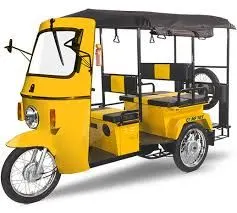
Elecric Rickshaw
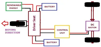
Block diagram of ERsh
COmponents used in Matlab Simulink model:
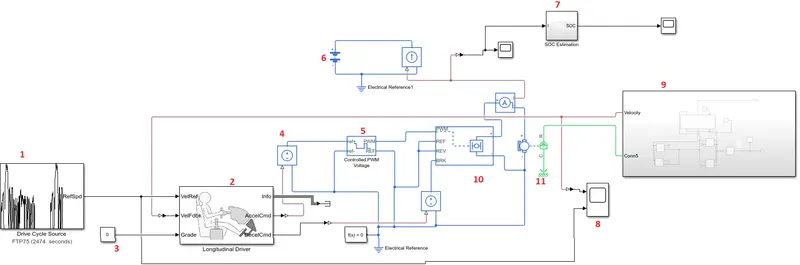
1. Drive cycle
2. Longitudinal Driver
3. Constant
4. COntrolled Voltage source
5. Controlled PWM source
6.Battery
7. SoC estimator
8.Scope
9. Vehicle body
10 H-Bridge
11. Dc motor
1. Drive cycle input.
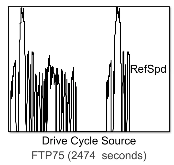
The drive cycle input is used to study the performance of the DC motor used in ERsh and to verify the performance of Battery used for the same application. In this model FTP drive Cycle source is used to verify the performance of ERsh. The simulation time is 2474 seconds'
2.Longitudinal Driver
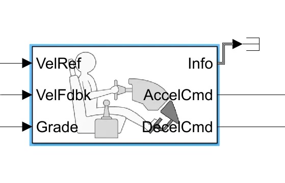
The inputs are Velhicle ref, Vehicke feedback and grading. The outputs are Acceleration command, Decelaration Command. The Vehicle reference signals are come from drive cycle, the vehicle feedback signals are get from out from the vehicle. The error generated according to the vehicle reference, acceleration command and decelearation command. It resembles PI controller.
3. Constant:
The Grading angle is 0 to the longitudinal driver block through grade=0;
4. Controlled current Source:
The controlled current source is given to the controlled PWM source, which is used to develop the pulses to the H bridge converter. The controlled current souce generate the signal according to the acceleration and decelaration mode.
5. Controlled PWM voltage source:
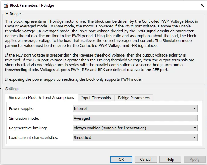
The controlled PWM source is used to fed the gate signals to H bridge converter. The H bridge converter paramters are set according to our application
6. Battery Bank: The source for DC motor is fed from H bridge internal source. But the application of the battery bank here to visulaize the its behaviour while running the motor. The variation of current accorsing to the input signal, i.e drive cycle is shown in the fig.
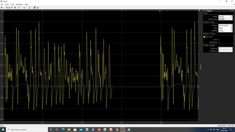
The current is negative at deceleration of drive cycle. The current is zero at zero speed of the drive cycle which resembles that the battery cannot used charge or discharge at that duration.
7. Soc Estimator
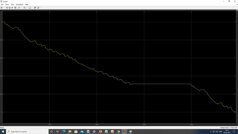
The Soc of the battery is discharges completly to zero, because of the high rated motor. The Soc is idle at the instant where the drive cycle has zero speed.
Vehicle Body:
The vehicle body is a sub system which consists of tyre and vehicle dynamics block
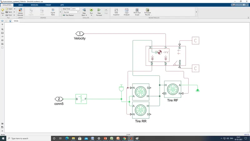
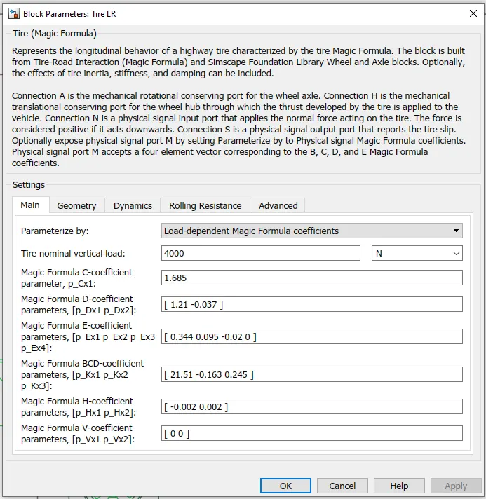
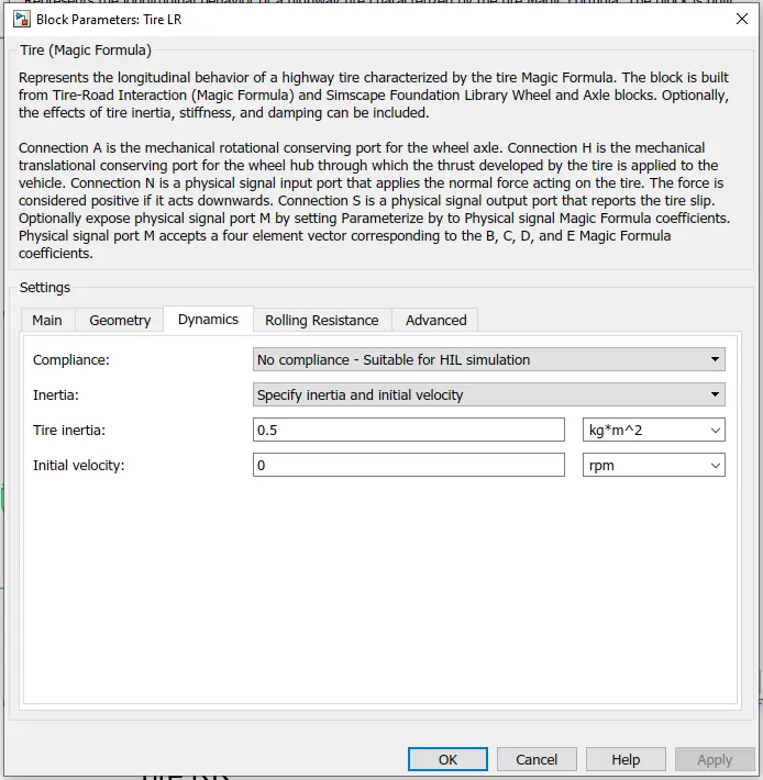
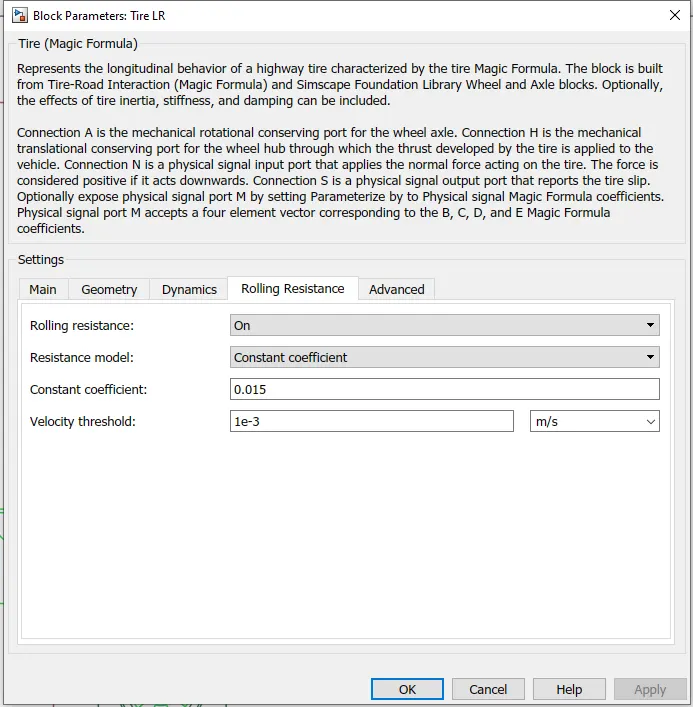
It has three tyres which has parameters as per below figure.
The vehicle dynamics have the following parameters.
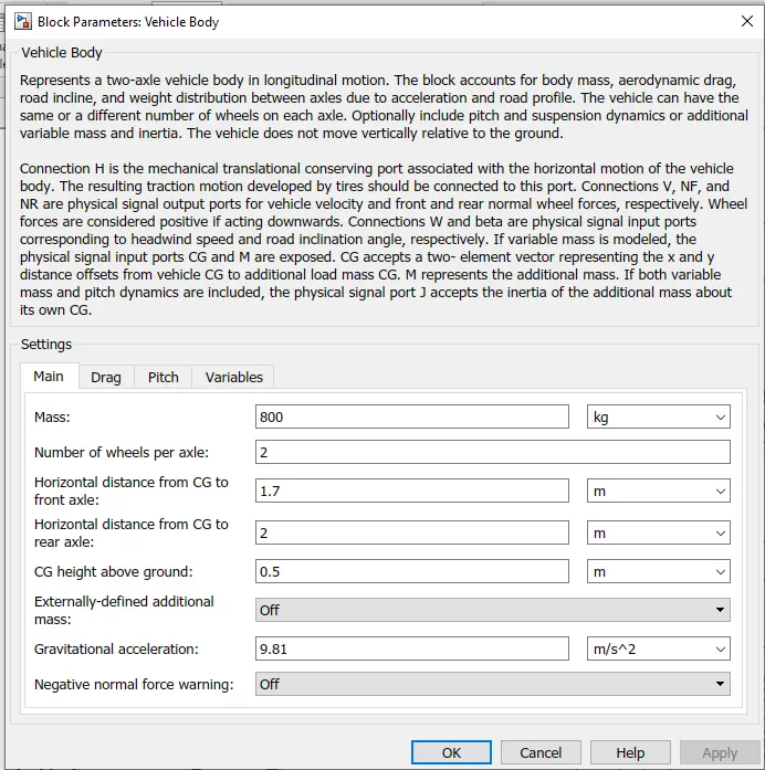
The mass and other parameters are shown in the figure
The wind velocity and grade angle is taken as 5 and 0 respectively.
DC Motor:
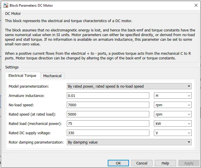
As explained at soc estimator the DC motor capacity is considered as 75 kW. So it is fatly discharge as per the motor requirements.
H-Bridge converter:
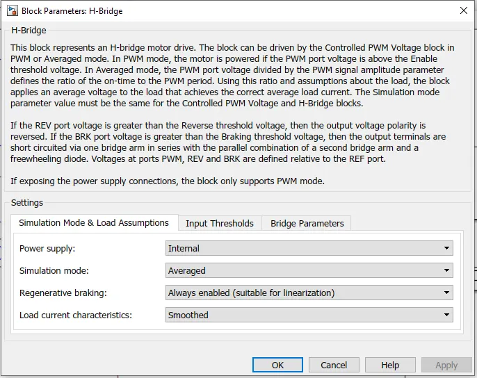
The H bridge converter is bi directional converter which has following parameters
Results
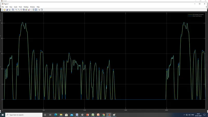
The results of the model is to compare, whether the vehicle is following the input drive cycles, The drive cycles are fed to the vehicle through PWM and h bride converter and the feed back from the vehicle body is given to longitudinal driver which changes the speed according to the requirements of the drive cycle. The results are shown such that the E- Rickshaw is almost follow the input drive cycle with less error.