Electric Rickshaw modelling-Mahindra Treo
- 1) Aim:
- Create a detailed MATLAB model of an electric rickshaw
- 2) Objectives:
- a) In the model the rear wheels driven by PM brushed type motor
- b) Make an excel sheet of all input and assumed data
- c) For any three standard driving cycles show energy consumption, the temperature rise of motor and controller for 100 km constant speed driving at 45 km/h.
- 3) Introduction, Vehicle specifications, vehicle modeling(all subsystems with formulas used) and block used in Simulink modeling:
- a) Introduction
- The popularity of Autorickshaw among Indians is such that it is a medium of commutation for the normal man. About 1.5 million battery-powered, three-wheeled rickshaws – a fleet bigger than the total number of electric passenger cars sold in China since 2011.
- As many as 11,000 new e-rickshaws hit the streets every month, and annual sales are expected to increase about 9 percent by 2021, according to consulting firm A.T. Kearney. Three-wheeled vehicles make up a $1.5 billion market, and manufacturers of electric versions include Mahindra & Mahindra Ltd and Kinetic Engineering Ltd, along with smaller outfits that assemble parts imported from China.
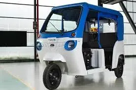
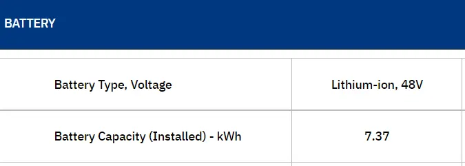
- An attempt has been made to model Mahindra treo electric rickshaw. The Mahindra Treo is aimed to be a clean and silent mobility solution for the city. The design remains identical to a conventional three-wheeler or what we dearly call an auto-rickshaw which is a popular choice among Indians. The Mahindra Electric Treo is powered by a 7.47kWh Li-ion battery which makes 5.4kW and 30Nm of torque. The battery can be charged to its full capacity in three hours and 50 minutes. The driving range is claimed to be 170 kilometers and has a top speed of 45km/h.
- b)Vehicle modeling-Body dynamics
- Since data like the coefficient of drag, rolling resistance, and gear ratios the data was taken from a BAJAJ RE model which is similar to treo from a paper titled "Modelling, design, and control of a light electric vehicle with hybrid energy
storage system for Indian driving cycle". - Vehicle dynamic modelling-By using Newton’s law of motion, the vehicle is modeled as a load by considering various longitudinal forces acting on it.
-
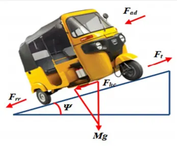
- The tractive force, Ft, required to drive the wheels by overcoming resistive force is given by Ft = Frr + Fad + Fhc +Fla +Fva, where Frr is the rolling resistance force, Fad is the aerodynamic drag, Fhc is the hill-climbing force, Fla is the
linear acceleration force and Fva is the rotational acceleration force - Using the obtained instantaneous tractive forces and the speed of the vehicle, the tractive power required at wheels is calculated as
Tractive power, Pt = Ft*v - Coefficient of roll resistance(Crr)=0.015
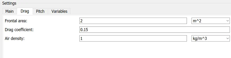
- Frontal area = 2 m^2
- Air density is taken as =1 Kg/m^3
- Coefficient of drag = 0.44
- Vehicle kerb weight = 377 kg
- Each tyre bears a weight of W/3
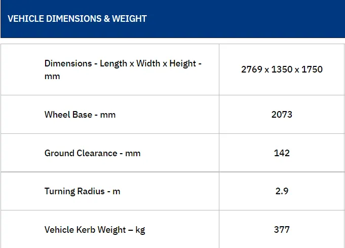
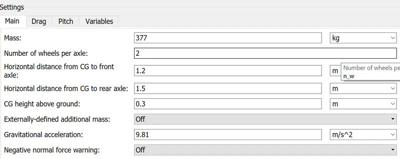
- The vehicel specifications and factors that contribute of resistive forces are input into below block called vehicle body.
-
-
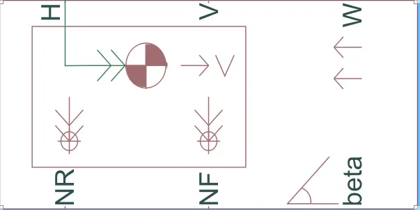
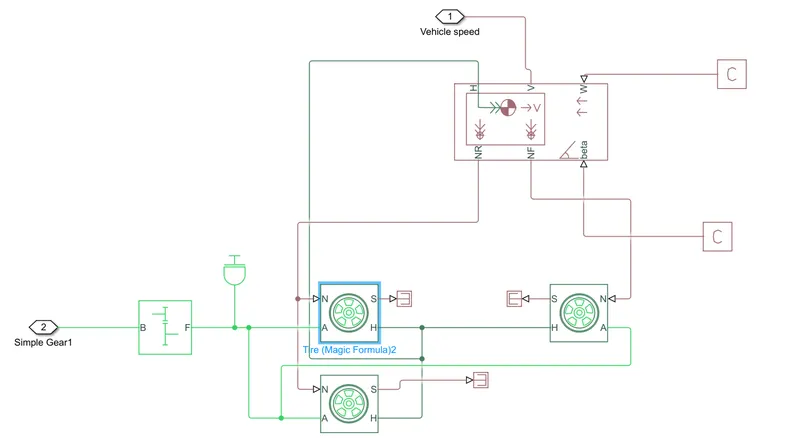
The block represents a two-axle vehicle body in longitudinal motion. The block accounts for body mass, aerodynamic drag, road incline, and weight distribution between axles due to acceleration and road profile. The vehicle can have the same or a different number of wheels on each axle.Connection H is the mechanical translational conserving port associated with the horizontal motion of the vehicle body. The resulting traction motion developed by tires should be connected to this port. Connections V, NF, and NR are physical signal output ports for vehicle velocity and front and rear normal wheel forces, respectively.
- vehicle body parameters
- Gear ratio=Nm*rw*pi/60*Vmax
- The gear system is obtained via a simple gear block.It epresents a fixed-ratio gear or gear box. No inertia or compliance is modeled in this block. You can optionally include gear meshing and viscous bearing losses. The gear ratio is varied for the reference velocity to match the output.
- Gear paramters

- Interia block- The block represents an ideal mechanical rotational inertia.
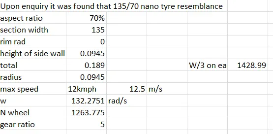
- In mahindra treo the tyre dimensions are 3.75*12 which is similar to a tata nano tyre with specification 130R/75. The wheel radius is calculated by
- Aspect ratio= 100%
- Height of side wall= (aspect ratio/100)* Section width =(100/100)*90=90mm
- Total wheel diameter= rim diameter + 2*height of side wall
- It comes out as 0.22 m
- The required wheel torque can be calculated from, T req = FT*rw.
- The three wheeler has a vertical load of W/3 acting on each
- The tires are represented by: Represents the longitudinal behavior of a highway tire characterized by the tire Magic Formula.
-

- In tyres the magic formula evaluates forces by peak longitudinal forces acting on vehicle. The inside parameters are given as:
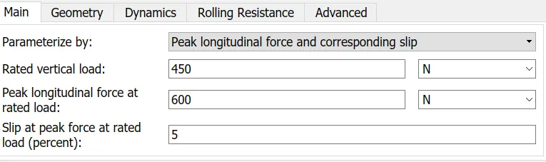
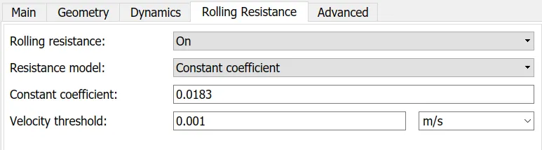
- The vehicle dynamics which can be also called as vehicle dynamics blocks which produces the velocity as response to drive cycles is represented below. Here in vehicle block zero gradient and wind speed are given 0 values via ps constant block.
-
- c) Motor selection
- A permanent magnet DC motor is used as it is intended for LEVs. It exhibits better performance in terms of efficiency, fast response, simple structure, high torque, and easier maintenance.
- Then, the motor power is calculated from the tractive power using motor power, Pm = Pt/nt where nt is the efficiency of transmission. The transmission effieciency is assumed as 95%.
- Any motor can operate above its rated voltage value for some amount of time. Since the drive cycle has variation operating points of high speed and the continous operation needs a constant monitoring of motor temperature. The rated voltage is 48 V.
- This is followed by the development of a motor drive
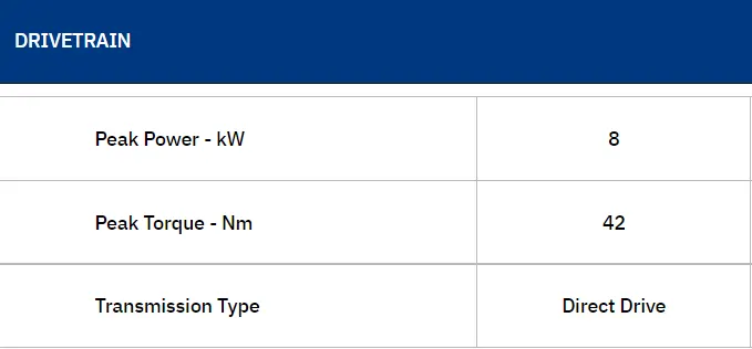
- The motor drive used in treo has a peak power of 9KW. The rated value is assumed as 6.5 KW
- Simple DC motor block-
This block represents the electrical and torque characteristics of a DC motor.The block assumes that no electromagnetic energy is lost, and hence the back-emf and torque constants have the same numerical value when in SI units. Motor parameters can either be specified directly, or derived from no-load speed and stall torque. The rated values are obtained by primary research. The temperature sensing port is on, so the sense the motor temperature during different drive cycles.The motor temperature is mentioned at every 25 deg C.
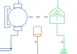
- Block parameters
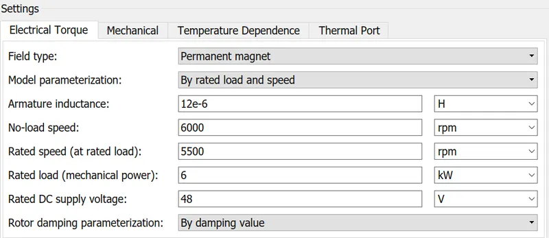
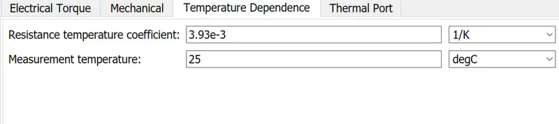
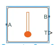
- The value of accelaration forces yield more power and must be given from the battery source. The top speed is according to drive cycle is met by adjusting the motor controller and PWM source. An ideal thermal sensor is used to sense the temperature and the B of sensorport is connected to a thermal reference.
- d) Motor controller and PWM Block
- A power electronic converter is an electronic device made of high power semiconductor switches that use different switching states to change the magnitude and waveform of voltage between input and output. Power converter circuits are used to control flow of energy by supplying right amount of current and voltage with help of power semiconductor switches. Power electronics deals with the conversion and control of electrical energy with the help of power semiconductor devices that operate in a switching mode, and, therefore, efficiency of power electronic apparatus may approach as high as 98–99%. They can be uni or bidirectional.
There are four possible types of power electronics converters namely
a) AC to DC converters (controlled rectifiers).
b) AC to AC converters (AC voltage controllers).
c) DC to AC converters (Inverters).
d) DC to DC converters (DC choppers). - PE circuits can apply power varying from tens of watts up to hundreds of megawatts. They have high energy conversion efficiency.In a power electronic circuit there exists only periodic linking of a power source to the load. This acts like an ideal switch where during a on state there is null resistance and during off state there is infinitesimally high resistance. The usage is preferred due to the absence of dissipation elements and power losses being nearly equal to zero.The duty cycle of a signal measures the fraction of time a given transmitter is transmitting that signal. This fraction of time determines the overall power delivered by the signal. Signals with longer duty cycles carry more power. This makes the signal stronger, more reliable and easily detected by receiving equipment. Signals with longer duty cycles require less efficient receivers than do signals with shorter duty cycles.
- Deepending upon maximum accelaration and retardation values in a duty cycle the values must be chosen to step up and step down voltages.
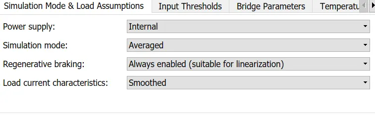
- H-Bridge- This block represents an H-bridge motor drive. The block can be driven by the Controlled PWM Voltage block in PWM or Averaged mode. In PWM mode, the motor is powered if the PWM port voltage is above the Enable threshold voltage. In Averaged mode, the PWM port voltage divided by the PWM signal amplitude parameter defines the ratio of the on-time to the PWM period. Using this ratio and assumptions about the load, the block applies an average voltage to the load that achieves the correct average load current. The Simulation mode parameter value must be the same for the Controlled PWM Voltage and H-Bridge blocks.
- During regenrative braking the battery is charged.
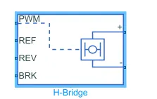
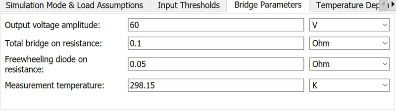
- H-Bridge paramters - Temperature measurement is enabled. At times it is possible to operate the motor at voltage higher than rated voltage.
- The voltage to the H bride,gate pulses must be controlled according to reference input for that a controlled PWM block us used and its user defined parameters are described below.
- Controlled PWM Block-This block creates a Pulse-Width Modulated (PWM) voltage across the PWM and REF ports.
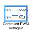
- PWM Block paramters- switching frequency represents how many times the pulses are given to open and close the h bridge
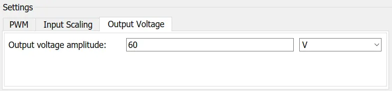

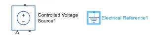
- In simscape the negative terminals are grounded via an electrical reference and to main a constant voltage accross a physical connected a control voltage source block is used.
- The motor along with the control and pwm source is represented as below:
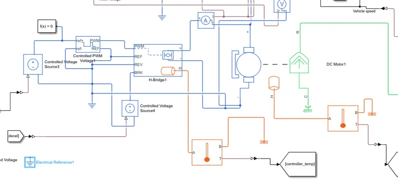
- The input to the controlled voltage source is the acceralation and deccelaration command from the longitudinal controller which is a PID controller.
- e) PID Control
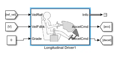
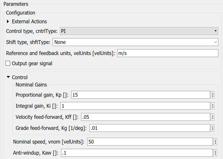
- PI control is used to establish reference tracking. A drive cycle represents the instanaoues velocity of the vehicle at various instant of time. The aim of using a controller is to establish a control over the output velocity such that the input reference velocity is tracked. This is done via a longitudinal driver block
- Longitudinal driver- A parametric longitudinal speed tracking controller for generating normalized acceleration and braking commands based on reference and feedback velocities.
- Block parameters- Using from and go to blocks the drive cycle inputs and velocity from vehicle body is fed into the ref and tracked signal inputs. The info blok is terminated using PS terminator. The entire subsystem is represented below:
-
- Block parameters
- f) Battery system
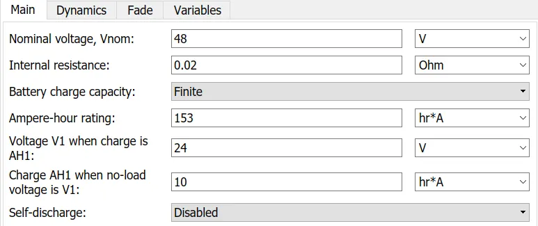
- The battery pack with the terminal voltage of 48 V is directly connected to the motor drive. The current is sensed from the motor in real time and a system is created to measure the SOC when a drive cycle is used. The battery capacity is estimated as product of battery volatge and battery capacity which is 153 Ah. This is rated capacity but battery capacity will be bit more.
- To represent a battery system a DC battery block is used, which is grounded and it receives motor current requirement as an input which is sensed through a current sensor.
- Battery block
- Battery block parameters
-
This block models a battery. If you select Infinite for the Battery charge capacity parameter, the block models the battery as a series internal resistance and a constant voltage source. If you select Finite for the Battery charge capacity parameter, the block models the battery as a series internal resistance plus a charge-dependent voltage source defined by:V = Vnom*SOC/(1-beta*(1-SOC))where SOC is the state of charge and Vnom is the nominal voltage. Coefficient beta is calculated to satisfy a user-defined data point [AH1,V1].
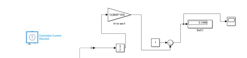
- A controlled current source is used to make a constant current flowwith no variation between the motor and battery. A soc calculation system is also made. Both of which are shown below:
- g) Temperature sensing subsystem
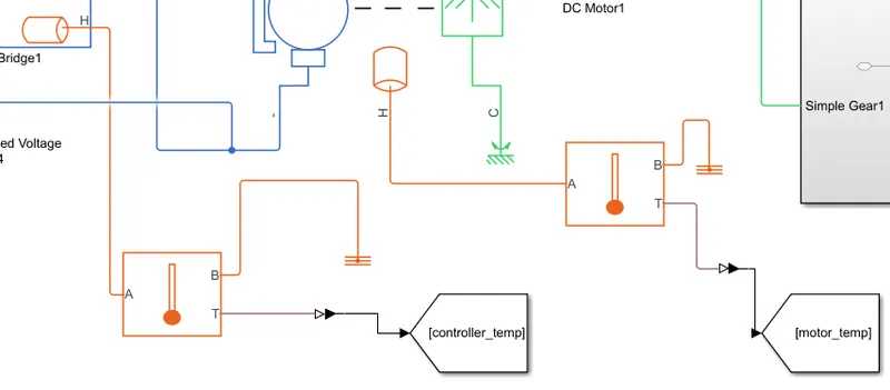
- Generally the motor temperature and controller temperature for any applications have specified limits of operation. The system to measure temperature for every 25 deg c is as below.
-
- h) Distance measurement for each drive cycle
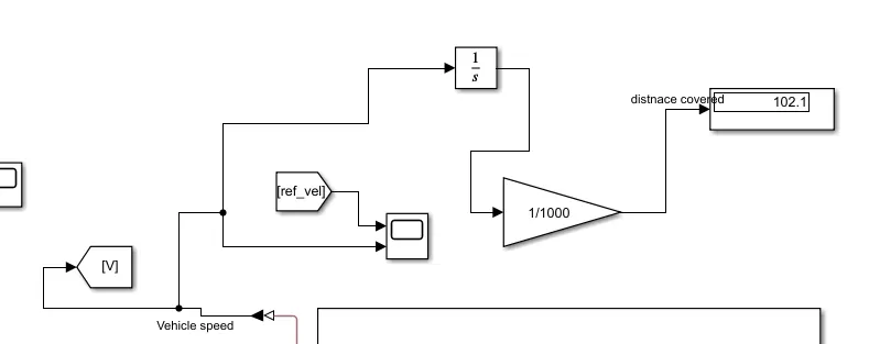
- The output velocity is integrated using integrated block, then divided by 1000 to obtain KM travelled during each drive cycle. The system is represented below.
-
- i) Drive cycle and multiport switch
- A driving cycle is a series of data points representing the speed of a vehicle versus time. Driving cycles are produced by different countries and organizations to assess the performance of vehicles in various ways, as for instance fuel consumption, electric vehicle autonomy and polluting emissions.
- The drive cycle are input with help of multiport switch which can be chosen. Say there are 3 drive cycle to be checked
- All three are input to multiport switch.
- There is an inport where a constant block can be attached
- If the second drive cycle in sequence has to be simulated then the corresponding number is kept in constant block.
- Three standard drive cycles used
- 1) FTP75
- 2) WOT 30
- 3) Indian urban drive cycle
- 4) Myspeed- which is a user defined drive cycle where auto is run continously for 45 kmph speed for 100 km
- To run a drive cycle simulation from matlab workspace a from workspace block is used
- A solver configuration block is also used in the system
- 4) Results and Inference (Simulink Model for e rickshaw treo):
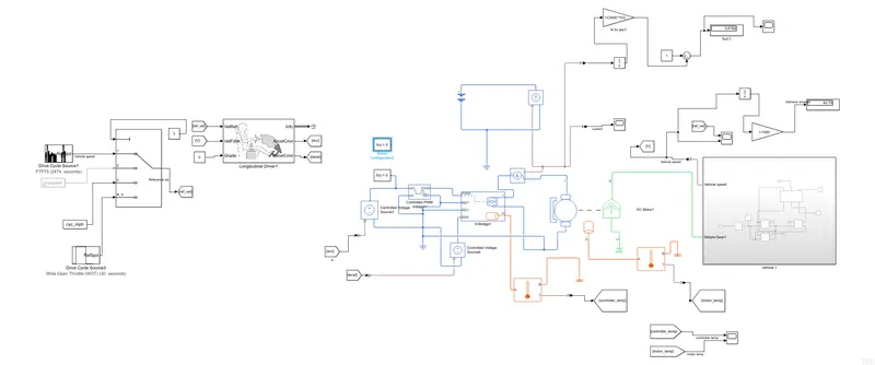
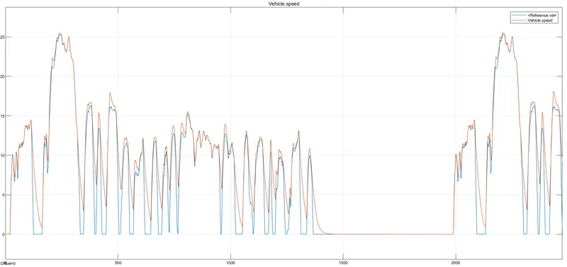
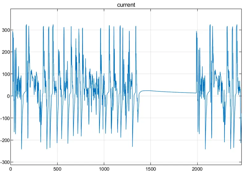
- 1) Study 1-using FTP75 drive cycle where simulation time is 2474 s
- a) Reference Speed vs Vehicle output speed
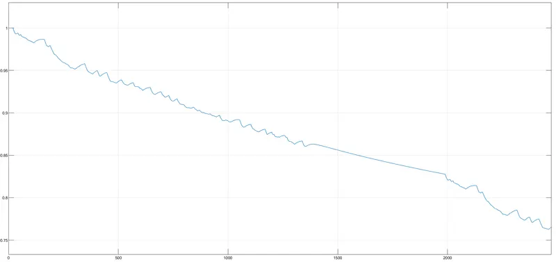
- b) SOC at end of the simulation
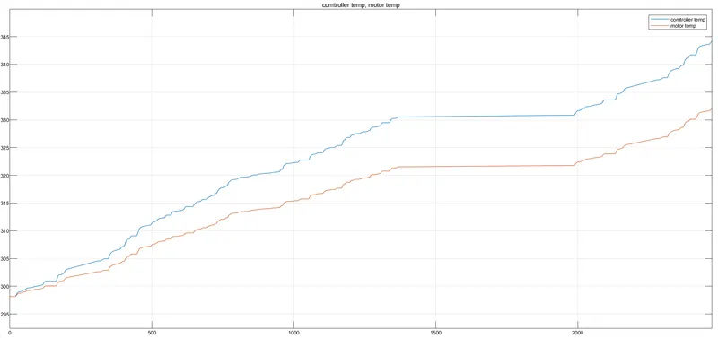
- c) Motor and controller temperature
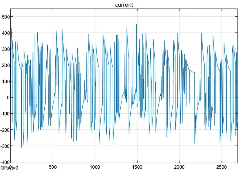
- d) Current drawn
-
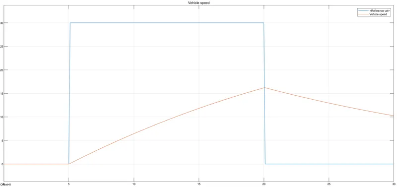
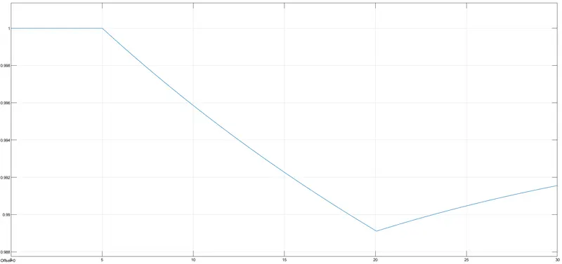
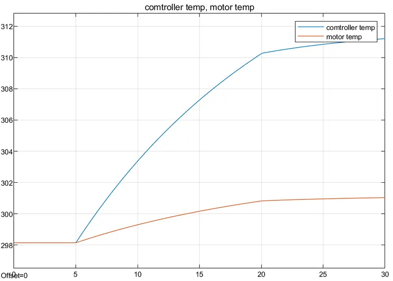
- 2) Study 2- WOT (30 s)
- a) Reference Speed vs Vehicle output speed
-
- b) SOC at end of the simulation
-
- c) Motor and controller temperature
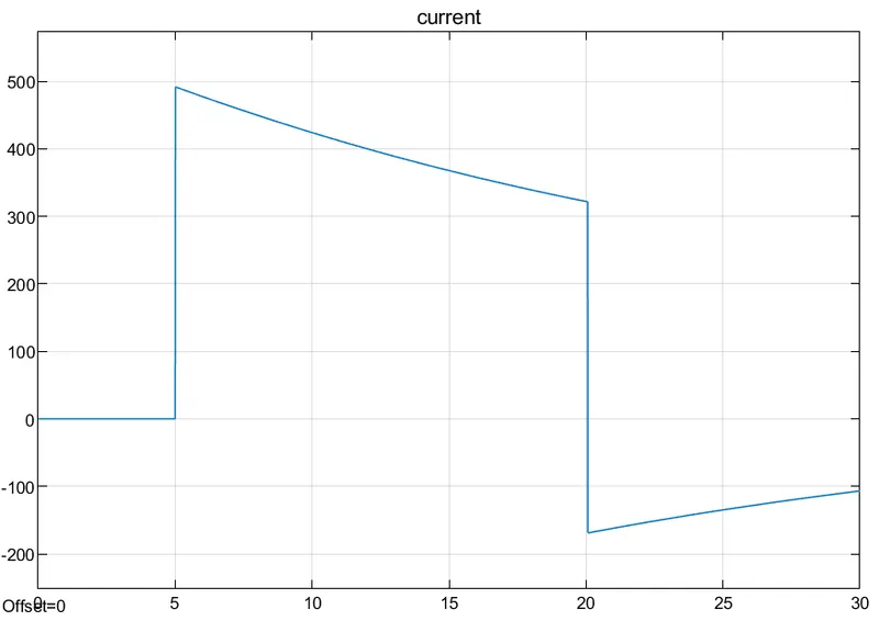
- 4) Current
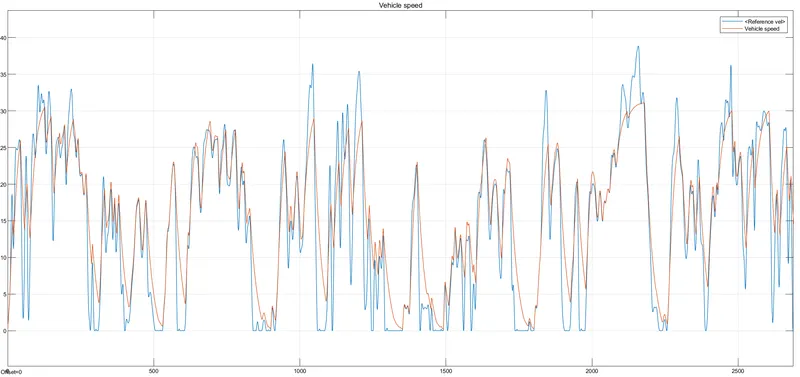
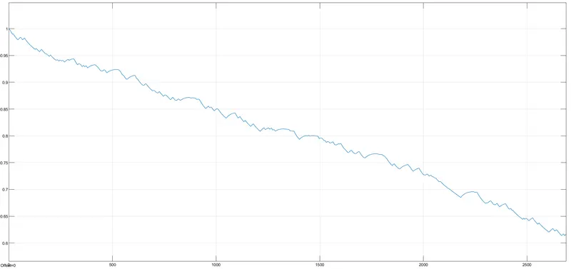
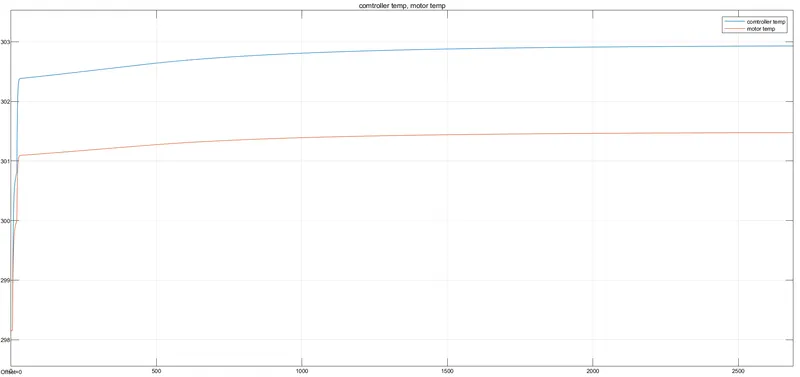
- 3) Study 3- Urban indian drive cycle-2690 s
- a) Reference Velocity vs Vehicle velocity output
-
- b) SOC at end of the simulation
-
- c) Motor and controller temperature
-
- d) Current
-
-
Drive cycle
SOC %
Motor temp (K)
Controller temp (K)
Inference
FTP75(2474s)
77
331
345
The large distance covered is responsible for the SoC. The high value of current is drawn from the battery to achieve high speeds in the drive cycle. The temperature observed in the controller is a result of frequent acceleration pulses to achieve high speed.
WOT(30s)
99.15
301
311
The drive cycle response is not matched. This might be due to approximations made in duty cycle values and the inability of the vehicle to attain such top speeds.
Urban indian(2690)
61.66
303
304
The Indian drive cycle has many retardations and start-stop operations hence heat dissipation time is there. But the distance covered compared to FTP75 is more hence SoC is less
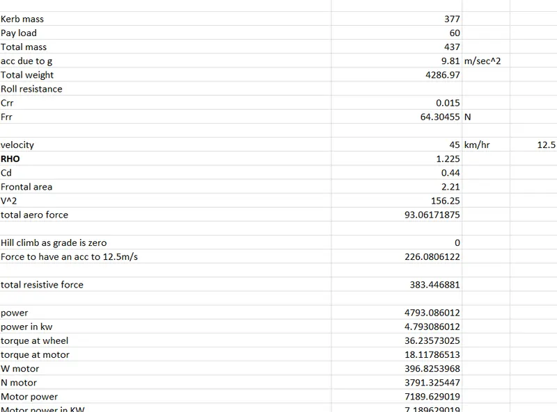
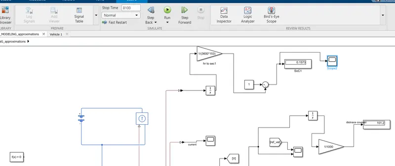
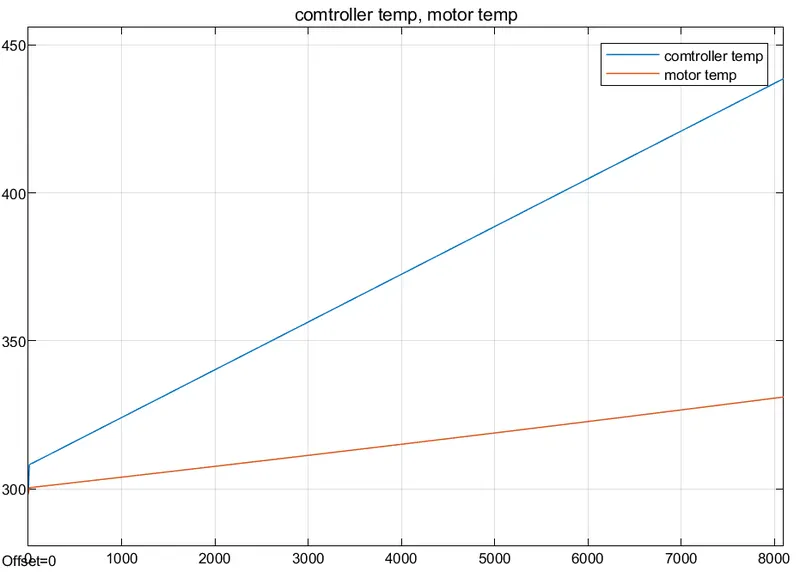
- There was a need to run the rickshaw at a speed of 45 km/hr for continous 100 minutes. All the approximations and paramterers such as tractive effort,battery,motor and controller ratings where chosen on basis of this.
- Tyre calculations:
- SoC decreases to 15% drastically as a result of near-to-top speed operation and a peak performance range operation. In speed torque characcteristics the motor will be operated mostly in region beyond rated operation called an intermittent zone.
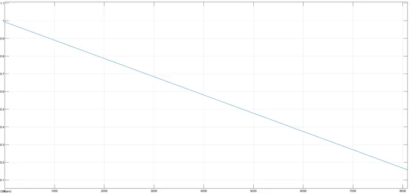
- The required distance was travelled with a simulation time of 8100 s
- The controller and motor temperature has shooted up:
- 5) Learning outcome
- a) It is always advisable to keep a higher rating battery and motor so as to get the desired output
- b) A constant operation of the motor in intermittent mode results in higher motor and controller temperature
- c) The response to throttle input is purely dependant on the gain values of the controller
- d) Continous high current rate affects the battery life
- e) A vehicle top speed has to be modeled separately for each drive cycle depending upon its region of usage
- Jerin JoyThank you very much sir for the detailed information. It would be very much helpful if you can help me on how to implement the same model using a BLDC motor instead of a DC motor. I have tried many times but I can't figure out the connection when we are using a BLDC motor block. I need it very much for my project. Hope you can give me some assistance.