Final Project: Electric Rickshaw modelling
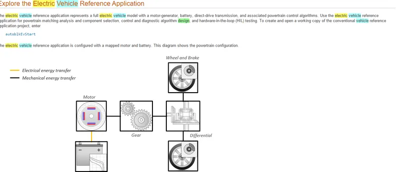
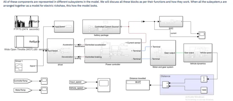
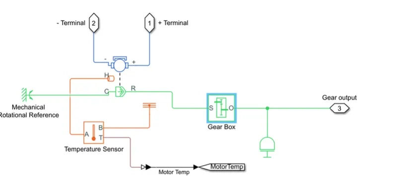
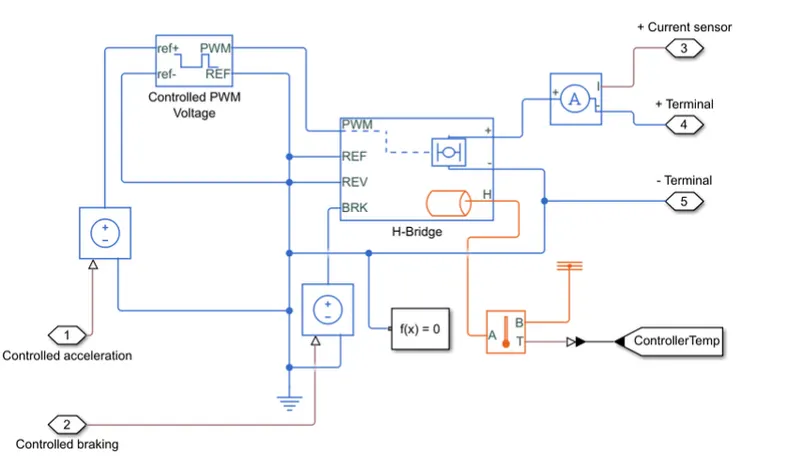
Power Controller: This subsytem is of prime importamce in electric powertrains. The controller does the main work of limiting and providing the required voltage. The system uses an HBridge block, controlled PWM voltage block, two controlled voltage source blocks for acceleration and deceleration(braking). This is because the system has regenrative braking. The H-bridge
calculates the current drawn from the battery for the generated PWM voltage. This current is given to the motor. This current is also sensed and the same is removed from and supplied to the
battery. The H-bridge also has a thermal port and it is connected to the temperature sensor to know the controller temperature.
H-Bridge:
This block represents an H-bridge motor drive. The block can be driven by the Controlled PWM Voltage block in PWM or Averaged mode. In PWM mode, the motor is powered if the PWM port
voltage is above the Enable threshold voltage. In Averaged mode, the PWM port voltage divided by the PWM signal amplitude parameter defines the ratio of the on-time to the PWM period.
Using this ratio and assumptions about the load, the block applies an average voltage to the load that achieves the correct average load current. The Simulation mode parameter value must
be the same for the Controlled PWM Voltage and H-Bridge blocks.
If the REV port voltage is greater than the Reverse threshold voltage, then the output voltage polarity is reversed. If the BRK port voltage is greater than the Braking threshold voltage, then
the output terminals are short circuited via one bridge arm in series with the parallel combination of a second bridge arm and a freewheeling diode. Voltages at ports PWM, REV and BRK are
defined relative to the REF port.
Drive control:
This subsystem compares the input speed and the vehicle speed. If the output is positive speed accelerating command is given from the controller. If the output is negative, deceleration
command is given from the controller output. This output is controlled by saturation blocks by giving the upper and lower limits. The PID controller is tuned and is a continuous time based.
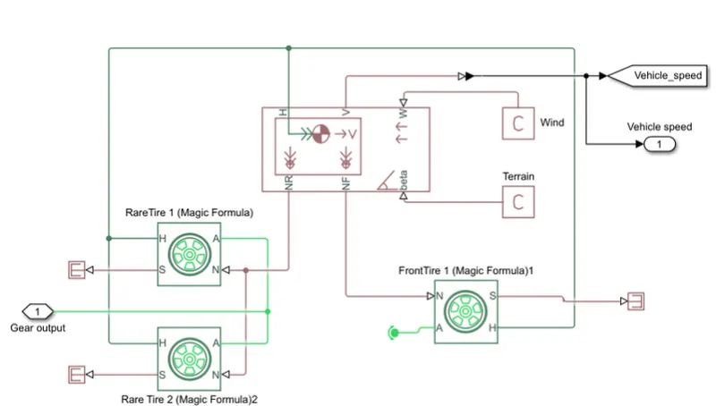
Vehicle body:
The vehicle body block takes normal load on front wheel and rear wheels, road inclination, wind speed, force developed by tyres etc. into consideration and calculates vehicle speed.
Represents a two-axle vehicle body in longitudinal motion. The block accounts for body mass, aerodynamic drag, road incline, and weight distribution between axles due to acceleration and
road profile. The vehicle can have the same or a different number of wheels on each axle. Optionally include pitch and suspension dynamics or additional variable mass and inertia. The
vehicle does not move vertically relative to the ground.
Connection H is the mechanical translational conserving port associated with the horizontal motion of the vehicle body. The resulting traction motion developed by tires should be connected
to this port. Connections V, NF, and NR are physical signal output ports for vehicle velocity and front and rear normal wheel forces, respectively. Wheel forces are considered positive if acting
downwards. Connections W and beta are physical signal input ports corresponding to headwind speed and road inclination angle, respectively. If variable mass is modeled, the physical signal
input ports CG and M are exposed. CG accepts a two- element vector representing the x and y distance offsets from vehicle CG to additional load mass CG. M represents the additional mass.
If both variable mass and pitch dynamics are included, the physical signal port J accepts the inertia of the additional mass about its own CG.