Final Project: Electric Rickshaw modelling
Electric Rickshaw modelling
AIM : To Create an Electric Rikshaw using MATLAB Simulink.
ABSTRACT :
we are going to build an Erikshaw which have three wheels,one in front and two in rear.its widely use in country like india.and its also called as tuk tuk.so,we will see in this project intoduction and specifications,we will use diff types of blocks using simulink library,we will use PM brushed type motor and use diff driving cycle to analyse the result for diff driving conditions and after that get a conclusion.
OBJECTIVE :
Create a detailed MATLAB model of an electric rickshaw (three wheel passenger vehicle) as per details below:
- Rear wheels driven by PM brushed type motor
- Assume efficiency points of motor controller and motor
- Make an excel sheet of all input and assumed data
- Results: For any three standard driving cycles show energy consumption, temperature rise of motor and controller for 100 km constant speed driving at 45 kmph.
Introduction :
Erikshaw have electric motor,controller,battery type electric and electronic components which will drive the rikshaw through rear wheel.many types of Erikshaw now a day avaiable like for passanger, for goods and carriage and in this also there are many subtypes also available in all this some of them have higher loading capacity some have higher safety longer life and all this but at the end all erikshaw use same components as per requirment just vehicle body will change as per requirment of safety,capacity and cost like factors.
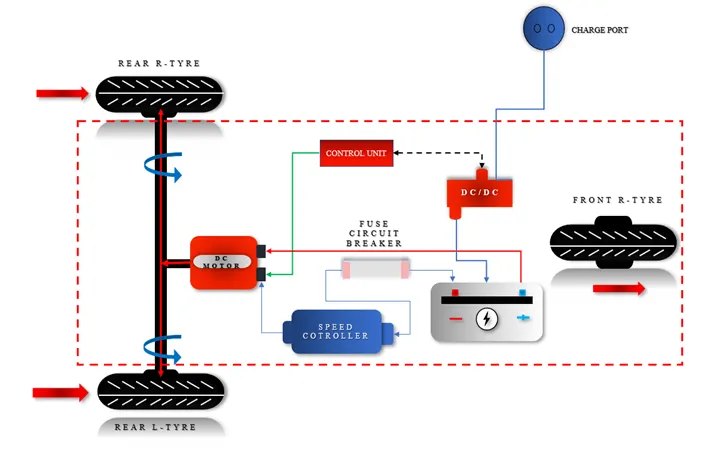
in india sells of Erikshaw will rise drastically,india is the huge market for Erikshaw and Eectric two wheeler.gov also give subsidy on pursase of Erikshaw.seels of electric vehicle rising contiounsly beacuse india have more no of middle class family so cost is also people consider but in Erikshaw fuel price is also high so people will go with Erikshaw option.and if the speed of Erikshaw is below 25 then we dont required driving licence aswell.so it also a pulse point.
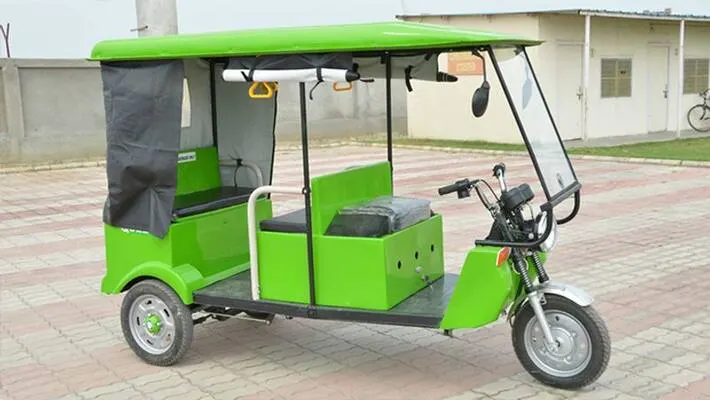
Company like mahindra,piogee have launched there Eriskhaw with diff types of models.it will create zero emission and noice so better for environment.many types of battery available like li ion,li phosphate, lead acid but generally we will use li ion beacuse it have many advantages compare to others like cost effective ,higher battery life and safe aswell.but many of the company gives lead acid battery option aswell beacuse its cost effective but battery life is less compare to li ion.
Specifications:
- Battery Type Lithium Ion 330 V 110 Ah
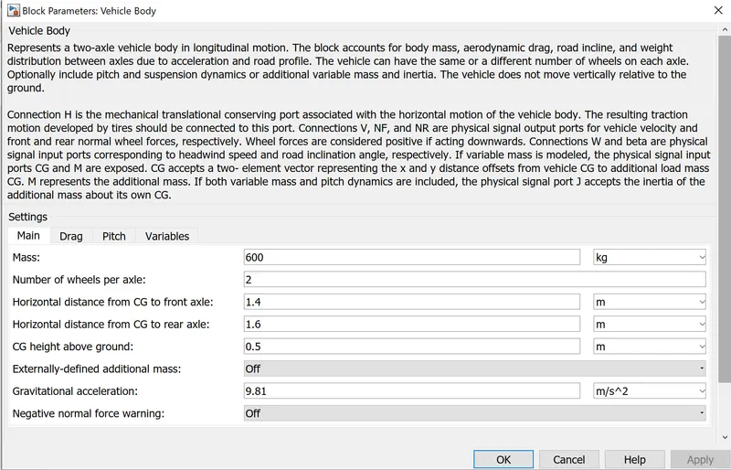
- Vehicle kerb weight 300 kgs
- Load capacity 400 kgs
- Vehicle speed below 25 kmph
- Driving range 140 km
- No of wheels per axel 2
- Frontal Area 91m
- Drag coefficient 0.5
- Wheel radius 306m
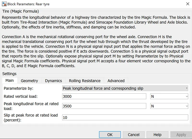
- Vertical load 3000 N
- Nominal Voltage 330 V
- Rated Capacity 110 Ah
- Initial SOC % 100
- Internal Resistance 2 ohm
PROCEDURE :
Vehicle body Subsystem Model :
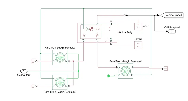
- this subsystem made of tyres,vehicle body and simple gear. in this subsystem the motor will transfer the power to the simple gear block for smooth and constant speed throughout the trasmission without any loss in speed from motor to tires.
- here we will give motor output to the rear two wheel of the Erikshaw and front tire is rotate freely.
- N is the normal force cause by the tires given to the vehicle body normal force port.
- The vehicle body has an H-hub,S-tire slip, N - normal force, A - axel connenction,wind velocity, inclination angle.
- the tire hub is connected as a common node to the vehicle body.The wind velocity and inclination angle is connected to PS constant block.velocity is the output port where we can get at which speed the vehicle is moving and also usefull for the find distance.
Block Parameters :
Tire :
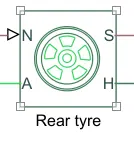
- Represents the longitudinal behavior of a highway tire characterized by the tire magic formula.the block is built from tire road interaction(magic formula) and simscape founation library wheel and axle blocks.optinally we can include rolling resistance,inertia and damping can be included.
Vehicle body :
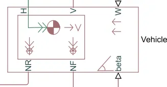
- Represents a two-axle vehicle body in longitudinal motion. The block accounts for body mass, aerodynamic drag, road incline, and weight distribution between axles due to acceleration and road profile. The vehicle can have the same or a different number of wheels on each axle. Optionally include pitch and suspension dynamics or additional variable mass and inertia. The vehicle does not move vertically relative to the ground.
- Connection H is the mechanical translational conserving port associated with the horizontal motion of the vehicle body. The resulting traction motion developed by tires should be connected to this port. Connections V, NF, and NR are physical signal output ports for vehicle velocity and front and rear normal wheel forces, respectively. Wheel forces are considered positive if acting downwards. Connections W and beta are physical signal input ports corresponding to headwind speed and road inclination angle, respectively
- here,we dont include angle and wind velocity so we give constant block there and give velocity V as output and NF,NR,H connected with tyre block.
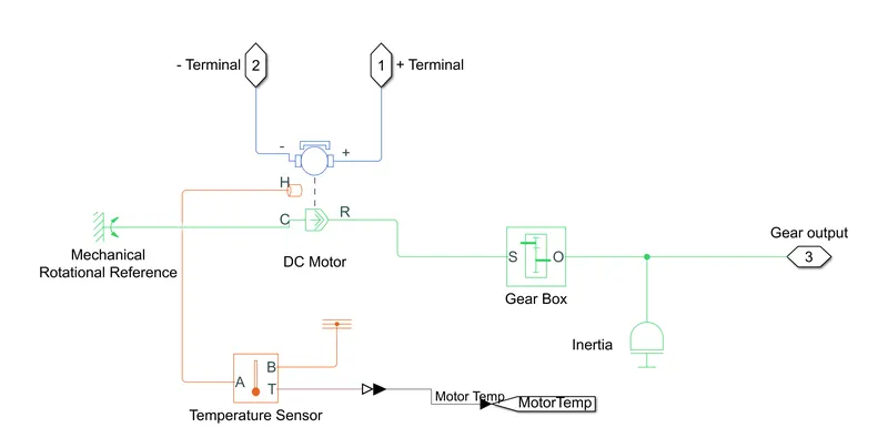
Motor and gear Subsystem Model (with temperature sensor) :
Gear :
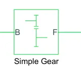
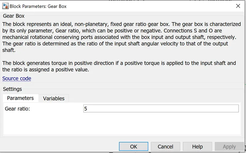
- Here,we are using simple gear.generally many types of gear avaiable in simulink library but beacuse its an EV so we can use simle gear beacuse we dont required to change the gear and this block also save our simulink time so its better to use this block.
- here, we have two ports B (base) and F (follower) base port will transfer the motor power to follower and then it will go to the axle and finally the wheel will rotates.
- we can change teeth ratio and rotation of the shaft.
DC Motor :
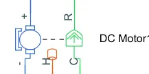
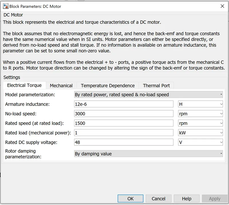
- This block represents the electrical and torque characteristics of a DC motor.
- When a positive current flows from the electrical + to - ports, a positive torque acts from the mechanical C to R ports. Motor torque direction can be changed by altering the sign of the back-emf or torque constants.
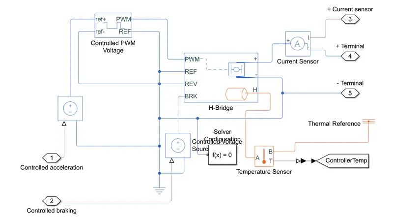
- The Motor controller will get input from the longitudinal driver. It tasks are to control the speed of the motor and drive according to the input of the driver. Majorly motor controlled we designed had two main parts named PWM voltage generator and H-Bridge.
- When deceleration occur this Hbridge will give an output from the positive and negative terminals of it. These negative & positive terminals are later connected to the DC motor and battery. All these components are the simscape electrical components so they need a connection to the solver configuration block which helps to solve the simulation.
- here i am using thermal part aswell to find the motor temperature.

Temperature sensor :
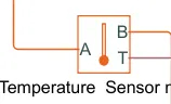
- The Temperature Sensor block represents an ideal temperature sensor, that is, a device that determines the temperature differential measured between two points without drawing any heat.
- Connections A and B are thermal conserving ports that connect to the two points where temperature is being monitored. Port T is a physical signal port that outputs the temperature differential value.
- The block positive direction is from port A to port B. The measured temperature is determined as T = TA – TB.
Motor Controller subsystem :
H bridge :
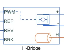
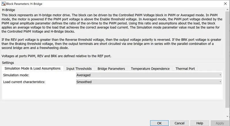
- This block represents an H-bridge motor drive. The block can be driven by the Controlled PWM Voltage block in PWM or Averaged mode.
- here, we are using avaraged simulation mode and smoothed load current to save out simulation time.
- we also use thermal port to find the temperature and + port is connected with voltage and current sensor and PWM and REF connected with controlled PWM voltage and REV and BRK is use for the regerative braking effect.
Controlled PWM Voltage :
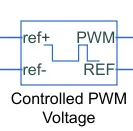
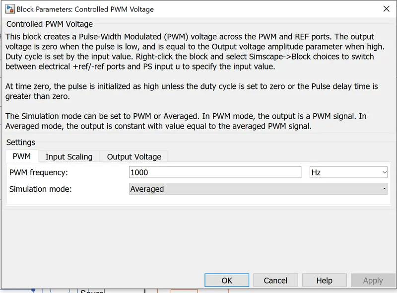
- This block creates a Pulse-Width Modulated (PWM) voltage across the PWM and REF ports. The output voltage is zero when the pulse is low, and is equal to the Output voltage amplitude parameter when high. Duty cycle is set by the input value. Right-click the block and select Simscape->Block choices to switch between electrical +ref/-ref ports and PS input u to specify the input value.
- Electrical input ports — The block calculates the duty cycle based on the reference voltage across its ref+ and ref- ports. This modelling variant is the default.
- PS input — Specify the duty cycle value directly by using an input physical signal port.
- The Simulation mode can be set to PWM or Averaged. In PWM mode, the output is a PWM signal. In Averaged mode, the output is constant with value equal to the averaged PWM signal.
Battery and SOC Subsystem:
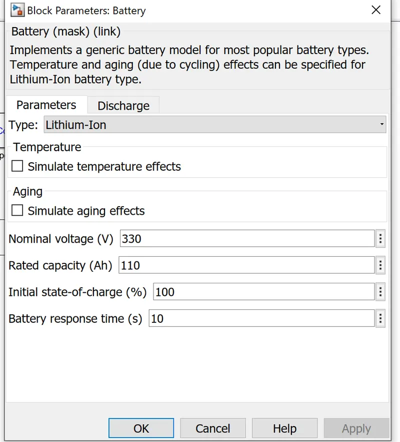
Battery :
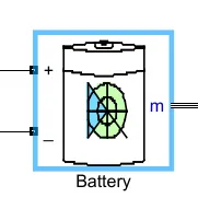
- The battery is required to power the controller and motor.
- The Battery block implements a generic dynamic model that represents the most popular types of rechargeable batteries.
- The battery has two-stage one is charging and another one is discharging state.
- Initial SoC is 100%
- The battery as a series internal resistance plus a charge-dependent voltage source
- defined by:
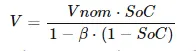
- where SOC is the state of charge and Vnom is the nominal voltage.Coefficient beta is calculated to satisfy a user-defined data point [AH1, VI].
- The battery has a positive and negative terminal which is given the voltage-controlled source where the battery consumption is controlled by the motor controller and then it is given to the SOC block.
Battery SOC :
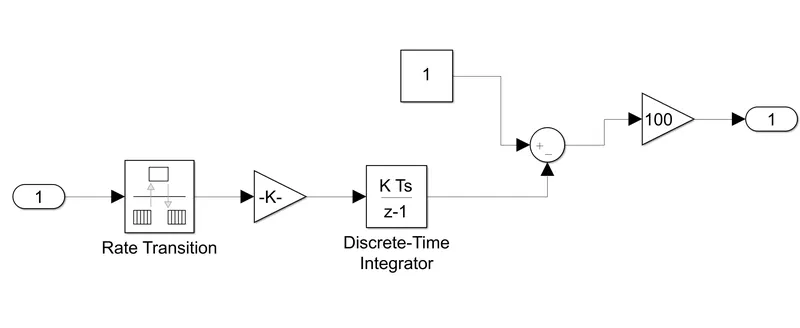
- SOC is percentage of battery present in vehicle.if the SOC is 100% means battery is full charge and if its 0 then its fully discharge.
- here,we use rate transistion block,gain block,discrete time intergrator block and it will get minus from 1.
- it means this value we get is minus from the whole battery which is 1 but in terms of 100% we need to use gain block and multiply the value with 100 so we can find the value in percentage.
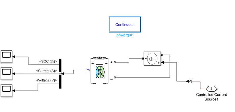
Controlled current source :
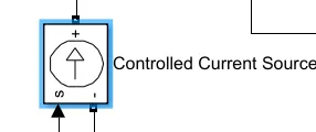
- The Controlled Current Source block converts the Simulink input signal into an equivalent current source. The generated current is driven by the input signal of the block. The positive current direction is as shown by the arrow in the block icon.
- here we can initialize the Controlled Current Source block with a specific AC or DC current. If we want to start the simulation in steady state, the block input must be connected to a signal starting as a sinusoidal or DC waveform corresponding to the initial values.
Bus selector :
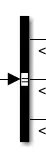
- This block accepts a bus as input which can be created from a Bus Creator, Bus Selector or a block that defines its output using a bus object. The left listbox shows the signals in the input bus.
- Use the Select button to select the output signals. The right listbox shows the selections. Use the Up, Down, or Remove button to reorder the selections. Check 'Output as bus' to output a single bus signal.
- here we connected battery input to this bus selector to find current SOC and voltage.
PowerGUI :
- The powergui block allows you to choose one of these methods to solve your circuit:
- Continuous, which uses a variable-step solver from Simulink.
- Discretization of the electrical system for a solution at fixed time steps
- Continuos or discrete Phasor solution
- The powergui block also opens tools for steady-state and simulation results analysis and for advanced parameter design.
Longitudinal driver :
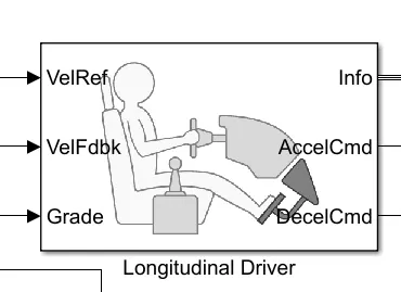
- A parametric longitudinal speed tracking controller for generating normalized acceleration and braking commands based on reference and feedback velocities.
- here vehref connected with our input drive cycle velfdbk is connected with velocity output so it will provide the real time speed and minimize the error between output velocity and ref velocity.
- info gives the output for the bus signal for diff in vehref and vehfdbk etc..
- here we take gradebility as constant block 1.means we dont count any inclination angle here.
- accelcmd connected with Controlled to the corresponding voltage source to generate accelaration and deaccelaration.
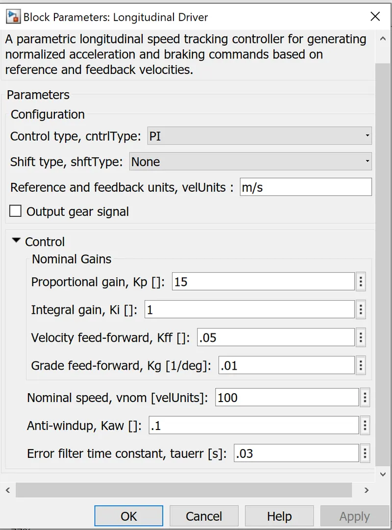
- here,we selected control type PI it will control the tracking windup and feed forward gains.
Multiport switch :
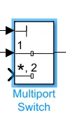
- here first input we use as a constant block so other block will according to it,and it will generate input signal corresponding to multiport switch output no.
- The inputs are numbered top to bottom (or left to right). The first input port is the control port. The other input ports are data ports.
Reference Velocity (Drive cycle) :
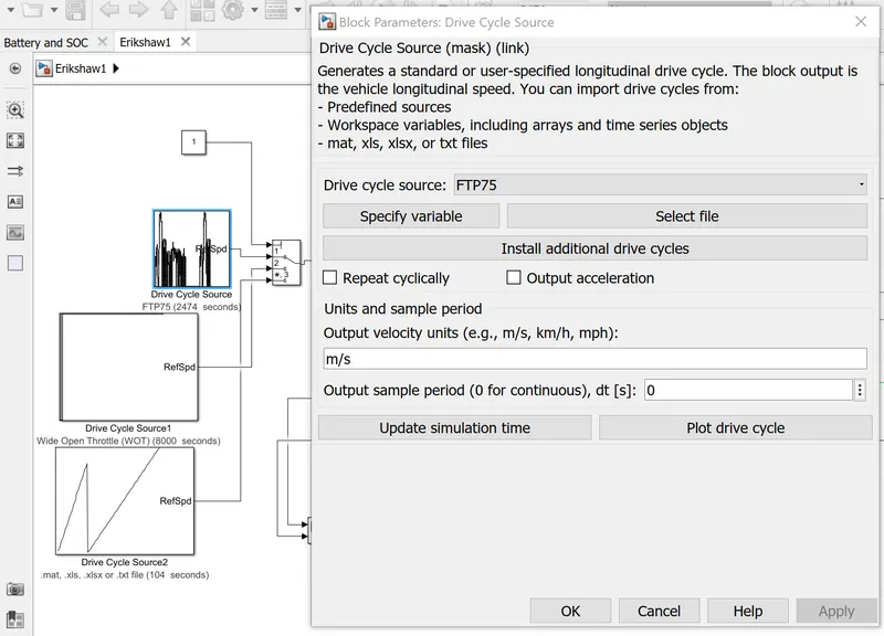
- Drivecycle is working like driver's input for a vehicle,here we will give some of the drive cycle from drive cycle block.
- it will help to understand the vehicle performance with diff speed and brakes time and all.
FTP 75 Drivecycle:
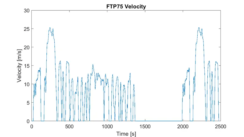
Generates a standard or user-specified longitudinal drive cycle. The block output is the vehicle longitudinal speed. You can import drive cycles from:
- Predefined sources
- Workspace variables, including arrays and time series objects
- mat, xls, xlsx, or txt files.
WOT (Wide open throttle) :
signal builder drive cycle :
Simulink model of an E rikshaw :
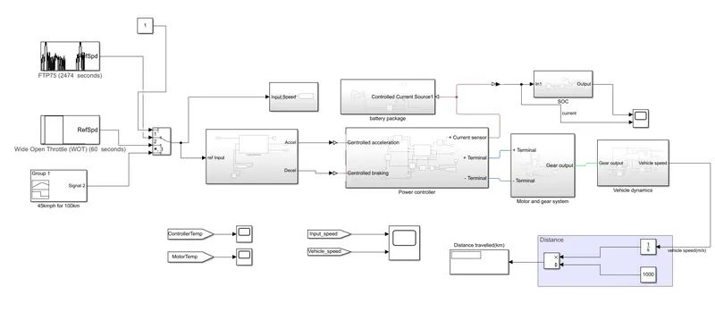
Simulink Explanation :
- Here we first give drive cycle as input then it will transfer the drive cycle to the controller through multiport longitudetanal driver command.
- here we use multiport switch to control the drive cycle and give this input to controller part.
- then controller will give input to the motor and it will transfer the power to gear and finally it come to the wheel.
- we required battery aswell so it also connect with controller and controll will measure the battery voltage an then as per throttle response it will give final output to the wheel and vehicle wheel rotate.
- here we tale feedback velocity aswell for better performance and minimize the error.
- we attached the scope and display block for result analysis.
OUTPUT :
for FTP75 drivecycle :
- multiport switch is set to 1.
- running the vehicle simulation with FTP75 drivecycle for 2474 second.
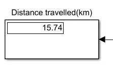
- the distance travelled is 15.74km
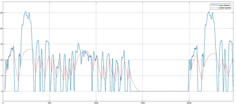
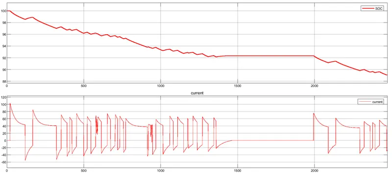
- here we can see that referance speed and actual speed both are not exactly similar.
- but it will try to follow the referance path very well and beacuse the speed of erikshaw is less then referance speed so it will not achive the speed similar to referance speed input.
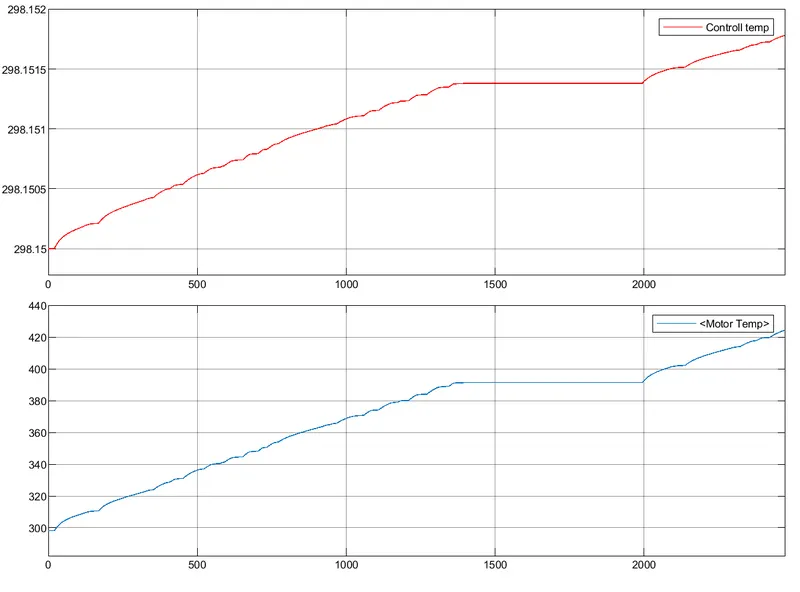
- the temp of motor is increased to above 420K
- the temp of controller is 298K
- battery state of charge is now 89% so 11% battery will down
For WOT drive cycle :
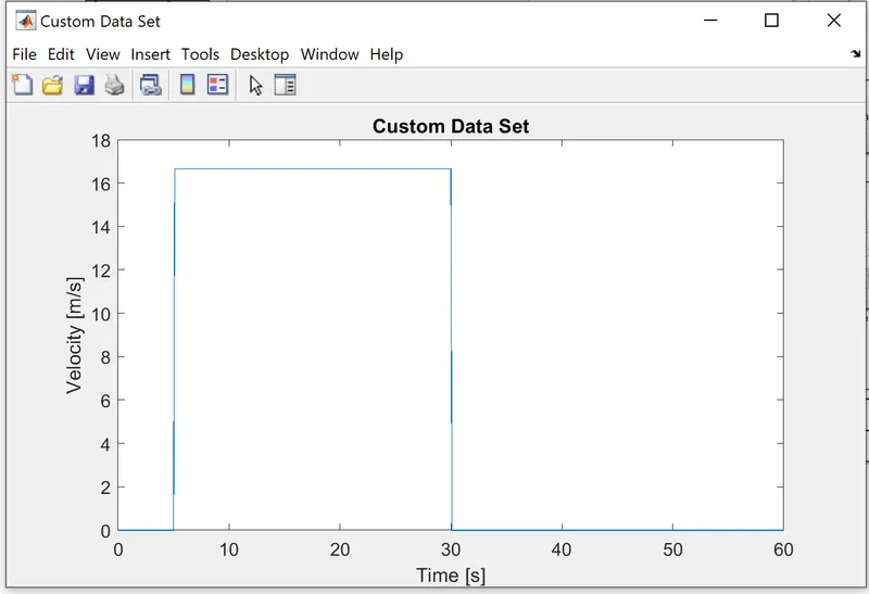
- multiport switch is set to 2
- By running the vehicle with Wide open throttle drivecycle for 100sec
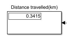
- the distance travelled is 0.341 km
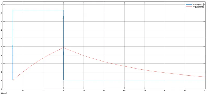
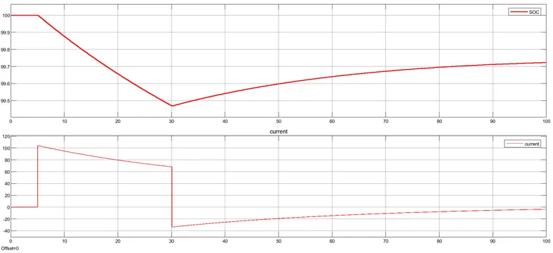

- here we can see that referance speed and actual speed both are very different.
- beacuse our refernace have sudden changes to its speed and brake but in real life we need to see the real life scenario like wind,drag,vehicle safety and driving safety,vehicle capability,load carrying capacity so real life sisuation is diff in this case.
- the temp of motor is around 304K
- the temp of controller is 298K
- battery state of charge is now 99.7% so 0.3% battery will down and beacuse of regenration we see the little up in slope so it will charge the battery.
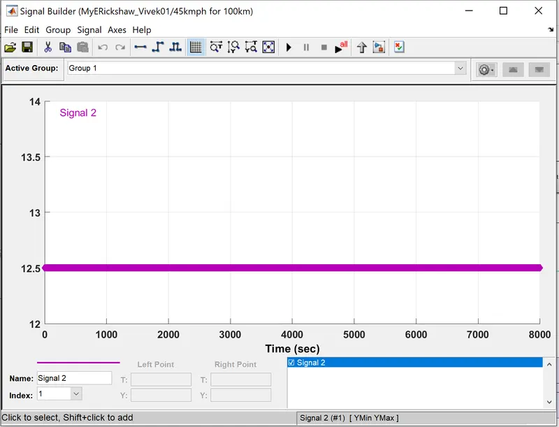
For Signal builder :
- multiport switch is set to 3.
- By running the vehicle with signal builder drivecycle for 8000 second.
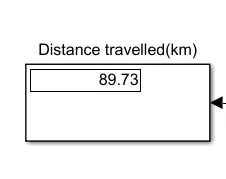
- the distance travelled is 89.73Km
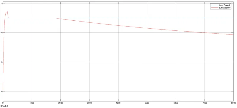
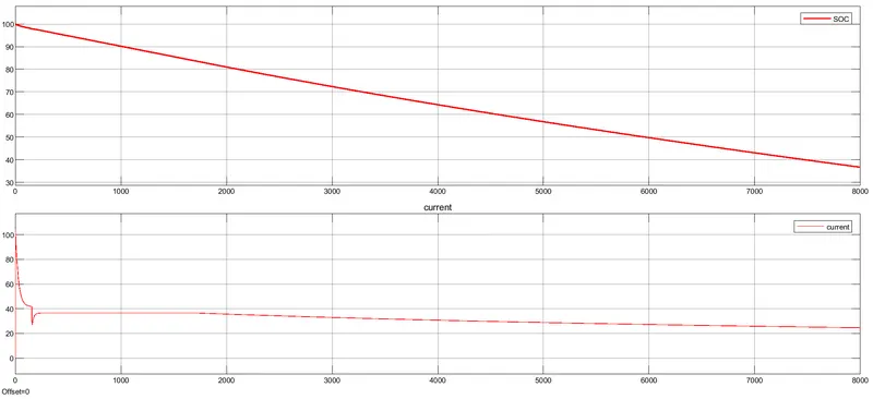
- here we can see that referance speed and actual speed both are similar in starting and after that actual speed is go down.
- beacuse temp also increasing and state of charge and current decreasing so it will create some effect on it.
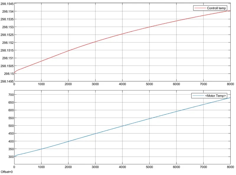
- the temp of motor is around 675K which is very high
- the temp of controller is 298K
- battery state of charge is now 37% so 63% battery will down beacuse there is no regenration there is no any charge happen.
CONCLUSION :
- Created a detailed MATLAB model of an electric rickshaw.
- understand the diff simulink blocks and its characterstics.
- Devloped understanding about energy consumption,temp rises and other parameters by using different drive cycles.
- so, after simulation we can see that the temp of motor and controller is continously increasing in our case beacuse we dont use any cooling device in this model.
- so in real life sisuation if we dont use air or liquid or any types of cooling then it will surely create a problem.
REFERANCES :
- https://www.mahindraelectric.com/vehicles/treo-electric-auto/
- https://www.researchgate.net/figure/E-rickshaw-specifications_tbl1_285781989
- https://en.wikipedia.org/wiki/Electric_rickshaw