Final Project: Electric Rickshaw modelling
Q) : Create a detailed MATLAB model of an electric rikshaw (three wheel passenger vehicle) as per details below :
Rear wheels driven by PM brushed type motor.
Assume efficiency points of motor controller and motor.
Make an excel sheet of all input and assumed data.
Results : For any three standard driving cycles show energy consumption, temparature rise of motor and controller for 100 km constant speed driving at 45 kmph.
(Note - The simulink model file should be compulsorily attached).
A). Electric Rikshaws have been becoming more popular in some cities since 2008 as an alternative to auto rickshaws and pulled rickshaws because of their low fuel cost, and less human effort compared to pulled rickshaws. They are being widely accepted as an alternative to petrol/diesel/CNG auto rickshaws. They are three-wheelers powered by an electric motor ranging from 650 to 1400 Watts. They are mostly manufactured in India and China. Battery-run rickshaws could be a low-emitter complementary transport for the low-income people, who suffer most from a lack of transport facility, if introduced in a systematic manner according to experts.
Design and Construction :
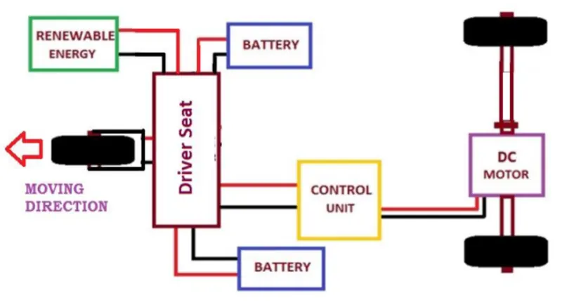
These rickshaws have a M.S(Mild Steel) tubular Chassis, consisting of three wheels with a differential mechanism at the rear wheels. The motor is brushless DC motor manufactured mostly in India and China. The electrical system used in Indian version is 48V and Bangladesh is 60V. The body design from most popular Chinese version is of very thin iron or aluminum sheets. Vehicles made in fiber are also popular because of their strength and durability, resulting in low maintenance, especially in India. Body design is varied from load carriers, passenger vehicles with no roof, to full body with windshield for drivers comfort. It consist of a controller unit.They are sold on the basis of voltage supplied and current output, also the number of mosfet (metal oxide field effect transistors) used. The battery used is mostly lead acid battery with life of 6–12 months. Deep cycle batteries designed for electric vehicles are rarely used. Weight of the electric car has also been a recurring design difficulty in them.
Block Diagram :
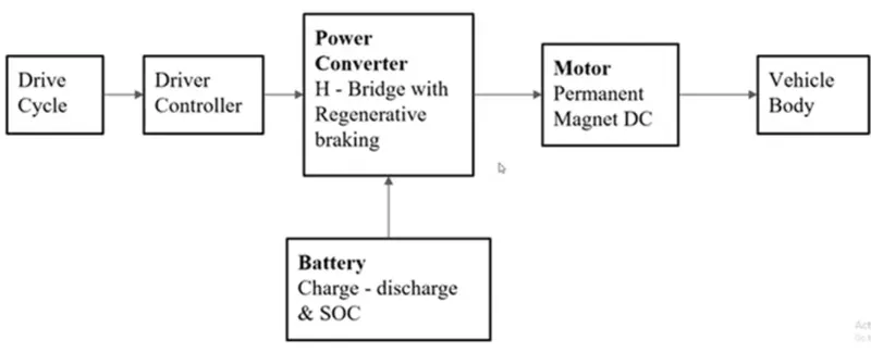 In an Electric Rickshaw the main blocks are
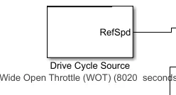
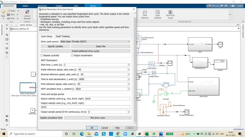
Drive cycle : A driving cycle is a series of data points representing the speed of a vehicle versus time. Driving cycles are produced by different countnes and organizations to assess the performance of vehicles in various ways, as for instance fuel consumption, electriC vehicle autonomy and polluting emissions.
Driver controller : The controller transforms the batteries direct current into alternating current (for AC motors only) and regulates the energy flow from the battery. In the early electric vehicles with DC motors, a simple variable-resistor-type controller controlled the acceleration and speed of the vehicle.
Power converter : In electric engineering, a DC to DC converter is a category of power converters and it is an electric circuit which converts a source of direct current (DC) from one voltage level to another, by storing the input energy temporarily and then releasing that energy to the output at a different voltage.
Motor : Today, majority of the electric cars are utilizing DC motors (4 kW and less power). Induction Motor is an exceptionally well known AC motor. A considerable lot of the advanced power EV (more than SkW), utilize Induction Motors.
Battery : Most plug-in hybrids and all-electric vehicles use lithium-ion batteries like these. Energy storage systems, usually batteries, are essential for hybrid electric vehicles (HEVS), plug-in hybrid electric vehicles (PHEVS), and all-electric vehicles (EVs).
Vehicle body : Car bodies are most often made of steel, which is strong and durable, but also pretty heavy-especially for electric power to move on its own.
Simulink Model :
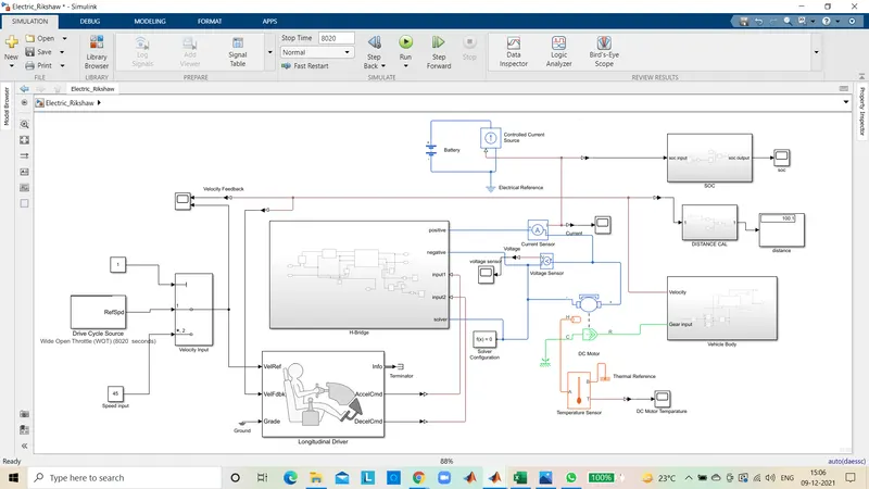
Component Used :
Vehicle Body :
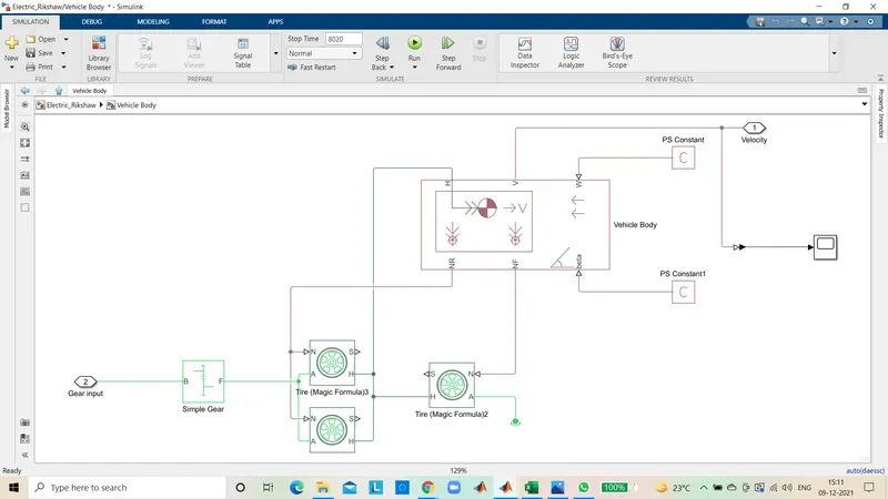
Vehicle Body :
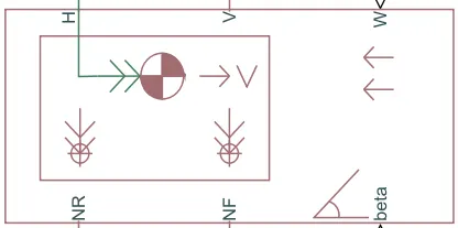
Represents a two-axle vehicle body in longitudinal motion. The block accounts for body mass, aerodynamic drag, road incline, and weight distribution between axles due to acceleration and road profile. The vehicle can have the same or a different number of wheels on each axle. Optionally include pitch and suspension dynamics or additional variable mass and inertia.
His the mechanical translational conserving port associated with the horizontal motion of the vehicle body. The resulting traction motion developed by tires should be connected to this port.
V, NF, and NR are physical signal output ports for vehicle velocity and front and rear normal wheel forces, respectively. Wand beta are physical signal input ports corresponding to headwind speed and
road inclination angle, respectively.
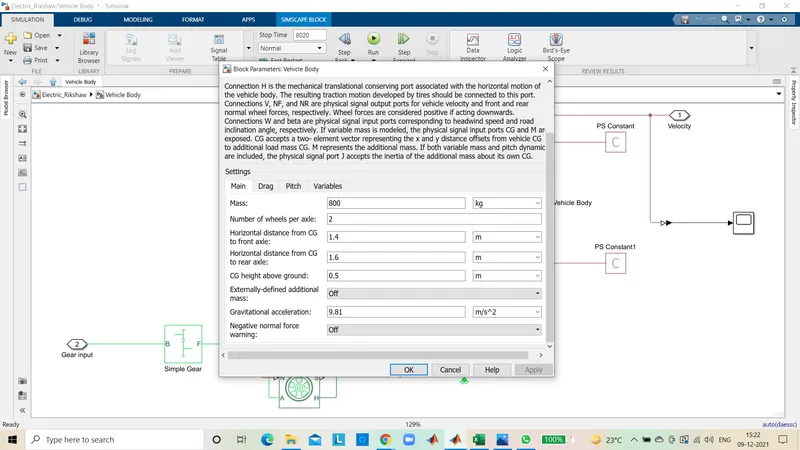
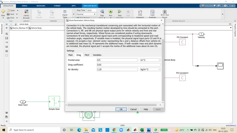
Specification of Vehicle body :
Tire (Magic Formula) :
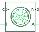
Represents the longitudinal behavior of a highway tire characterized by the tire Magic Formula. The block is built from Tire-Road Interaction (Magic Formula) and Simscape Foundation Library Wheel and Axle blocks. Optionally, the effects of tire inertia, stiffness, and damping can be included.
A is the mechanical rotational conserving port for the wheel axle.
H is the mechanical translational conserving port for the wheel hub through which the thrust developed by the tire is applied to the vehicle.
N is a physical signal input port that applies the normal force acting on the tire.
S is a physical signal output port that reports the tire slip.
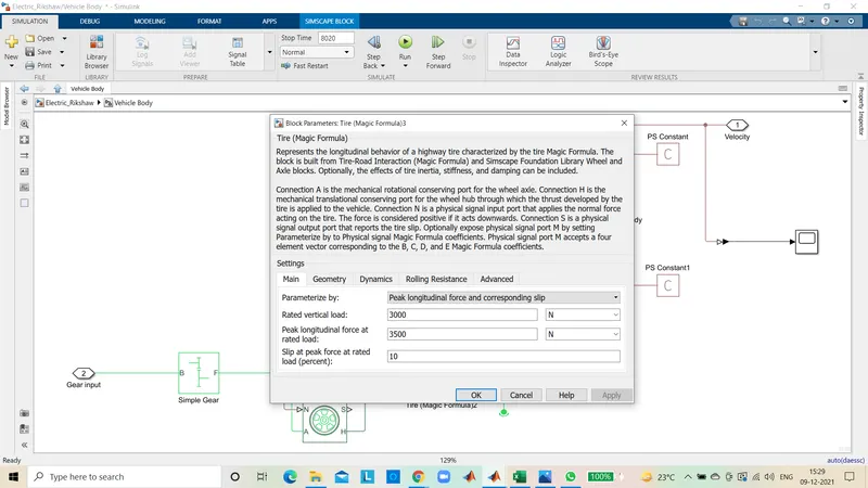
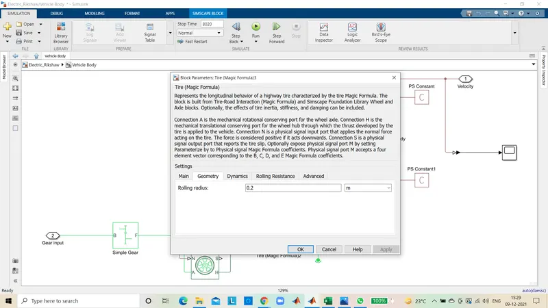
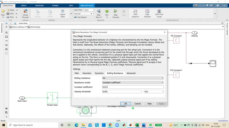
Specification of Tire :
Gear Box (magic formula) :
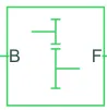
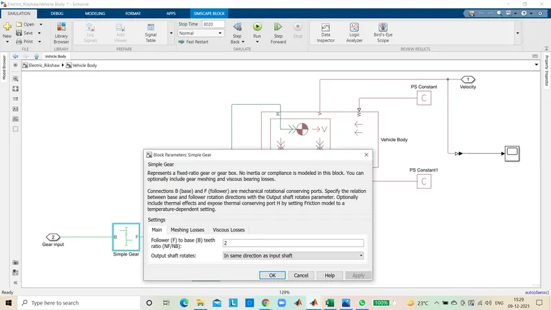
The block represents an ideal, non-planetary, fixed gear ratio gear box. The gear box is characterized by its only parameter, Gear ratio, which can be positive or negative. Connections S and O are mechanical rotational conserving ports associated with the box input and output shaft, respectively. The gear ratio is determined as the ratio of the input shaft angular velocity to that of the output shaft.
The block generates torque in positive direction if a positive torques applied to the irput shatt and the ratio is assigned a positive value.
Specifications of Gear Box :
PS Constant :

This block creates a physical signal constant.
Y = constant
The Constant parameter accepts both positive and negative values. The block output is a physical signal port.
This PS Constant is connected to the Vehicle Body port W and delta port for we can change the value of angle and wind velocity but we kept this value now one.
DC Motor :
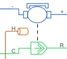
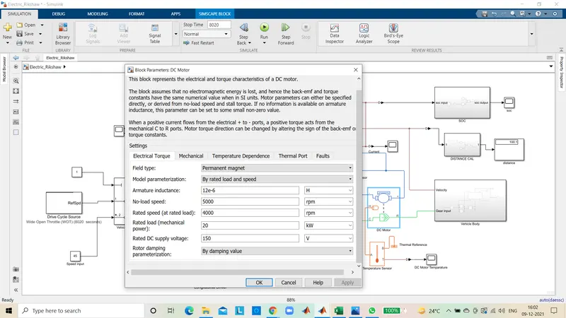
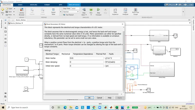
This block represents the electrical and torque characteristiCs of a DC motor. The block assumes that no electromagnetic energy is lost, and hence the back-emf and torque constants have the same numerical value when in SI units. Motor parameters can either be specified directly, or derived from no-load speed and stall torque. f no information is available on armature inductance, this parameter can be set to some small non-zero value.
When a positive current flows from the electrical + to ports, a positive torque acts from the mechanical C to R ports. Motor torque direction can be changed by altering the sign of the back-emf or torque constants.
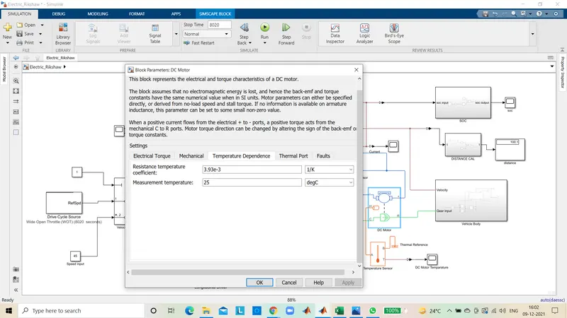
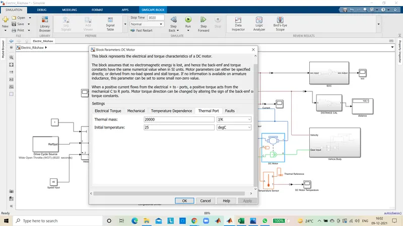
Specification Of DC Motor :
Thermal Port :
The block has an optional thermal port, hidden by default. To explose the thermal port, right-click the block in your model, and them from the context menu select Simscape > Block choicess > Show thermal port. This action displays the thermal port H on the block icon, and exposes the Temparature Dependance and Thermal Port parameters.
Use the thermal port to simulate the effects of copper resistance losses that convert electrical power to heat. For more information on using thermal ports and on the Temparature Dependance and Thermal Port parameter.
Temparature sensor :

This block measures temparature in a thermal network. There is no heat flow through the sensor. The physical signal port T reports the temparature difference across the sensor. The measurement is positive when the temparature at port A is greater than the temparature at port B.
DC Motor Controller :
H-Bridge :
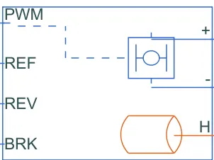
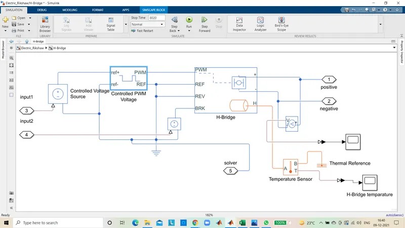
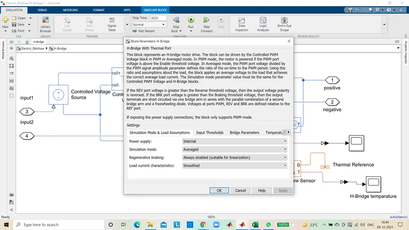
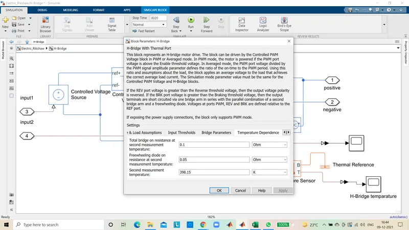
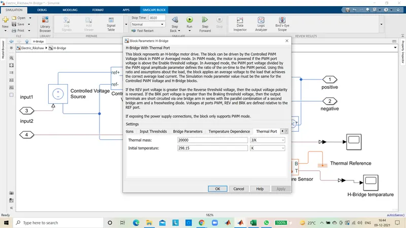
This block represents an H-bridge motor dirive. The block can be driven by the Controlled PWM Voltage block in PWM or Averaged mode. In PWM mode, the motor is poweredif the PWM port voltage is above the Enable threshold voltage. Iin Averaged mode, the PWM port voltage civided by the PWM signal amplitude parameter defines the ratio of the on-time to the PWM period. Using this ratio and assumptions about the load. the block applies an average voltage to the load that achieves the correct average load current. The Simulation mode parameter value must be the same for the Controlled PWM Voltage and H-Bridge blocks.
If the REV port voltage is greater than the Reverse threshold voltage. then the output voltage polarity is reversed. If the BRK port voltage is greater than the Braking threshold voltage. then the output terminals are short circuited via one bridge arm in series with the parallel combination of a second bridge arm and a freewheeling diode. Voltages at ports PWM, REV and BRK are defined relative to the REF port.
If exposing the power supply connections, the block only supports PWM mode.
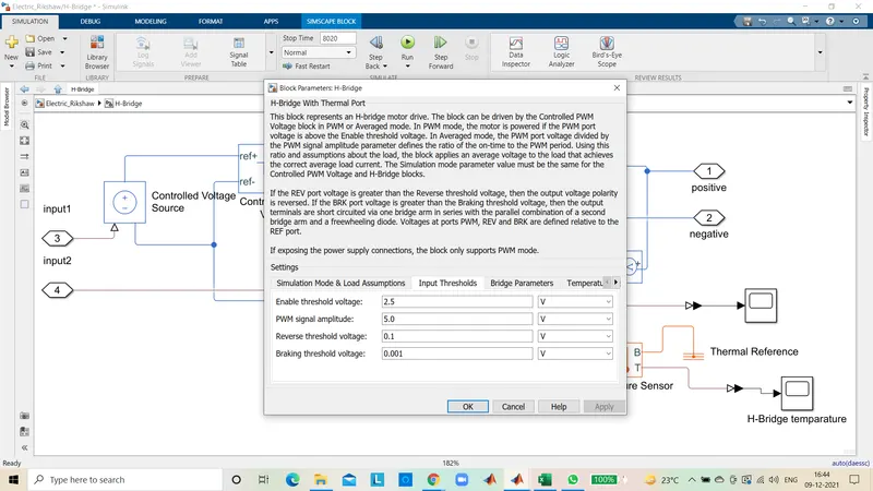
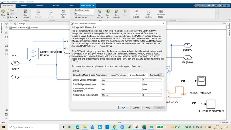
Specification of H - Bridge :
Controlled PWM Voltage :
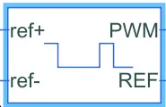
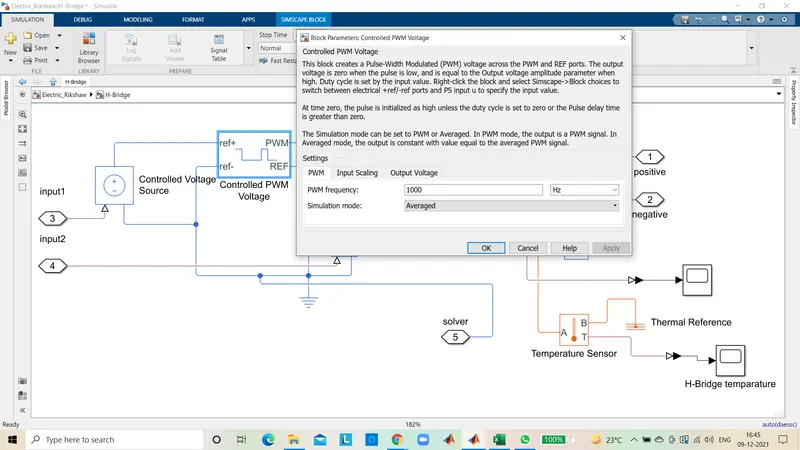
This block creates a Pulse-Width Modulated (PWM) voltage across the PWM and REF ports. The output voltage is zero when the pulse is low, and is equal to the Output voltage amplitude parameter when high. Duty cycle is set by the input value. Right-click the block and select Simscape-Block choices to switch between electrical ref/-ref ports and PS input u to specify the input value.
At time zero. the pulse is initialized as high unless the duty cycle is set to zero or the Pulse delay time is greater than zero.
The Simulation mode can be set to PWM or Averaged. In PWM mode, the output is a PVWM signal. In Averaged mode, the output is constant with value equal to the averaged PWM signal.
Specifications of Controlled PWM Voltage :
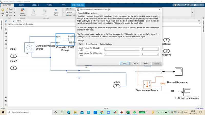
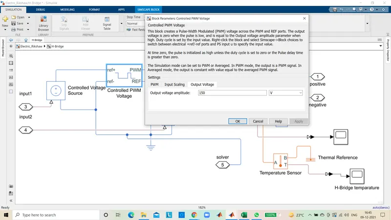
Controlled Voltage Source :
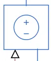
The block represents an ideal voltage source that is powerful enough to maintain the specified voltage at its ouput regardless of the current passing through it. The output voltage is V = Vs, where Vs is the numerical value presented at the physical signal port.
Current sensor :

The block represents an ideal current sensor, that is, a device that converts current measured in any electrical branch into a physical signal proportional to the current.
Connections + and - are conserving electrical ports through which the sensor is inserted into the circuit. Connection I is a physical signal port that outputs current value.
Electrical reference :

Electrical reference port, A model must contain at least one elctrical reference port (electrical ground).
Solver Configuration :

Each physical network represented by a connected Simscape block diagram requires solver settings information for simulation. The solver Configuration block specifies the solver parameters that your model needs before you can begin simulation.
Each topologocally distinct Simscape block diagram requires exactly one Solver Configuration block tobe connected to it.
Mechanical rotational reference :

This Block represents a mechanical rotational reference point, that is, a frame or a ground. Use it to connect mechanical rotational ports that are rigidly affixed to the frame(ground).
Battery :

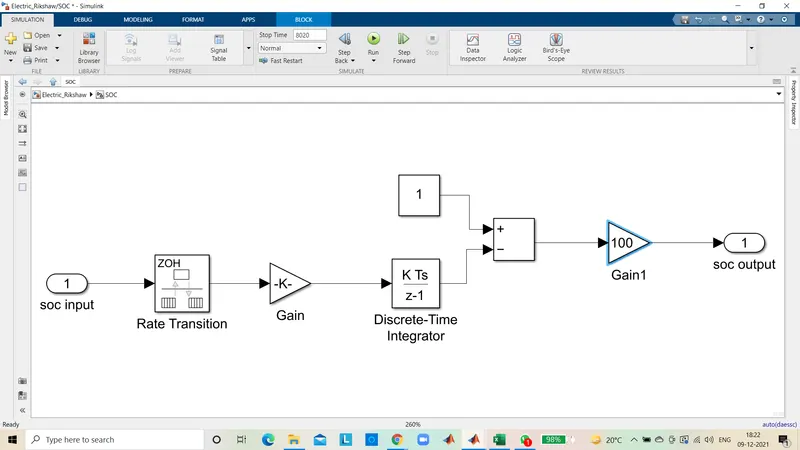
The SOC of a battery is a combination of voltage, charge/discharge current and internal resistance parameters to estimate its size. These parameters are also affected by a variety of uncertainties such as battery aging, temperature changes and usage status.
State of charge (SoC) is the level of charge of an electric battery relative to its capacity. The units of SoC are percentage points (0% = empty;100% full). An alternative form of the same measure is the depth of discharge (DoD), the inverse of SoC (100% = empty: 0% = ful), SoC is normally used when discussing the current state of a battery in use, while DoD is most often seen when discussing the lifetime of the battery after repeated use.
Knowing the amount of energy left in a battery compared with the energy it had when it was full gives the user an indication of how much longer a battery will continue to perform before it needs recharging. It is a measure of the short term capability of the battery. Using the analogy of a fuel tank in a car, State of Charge (SOc) estimation is often called the "Gas Gauge" or "Fuel Gauge" function.
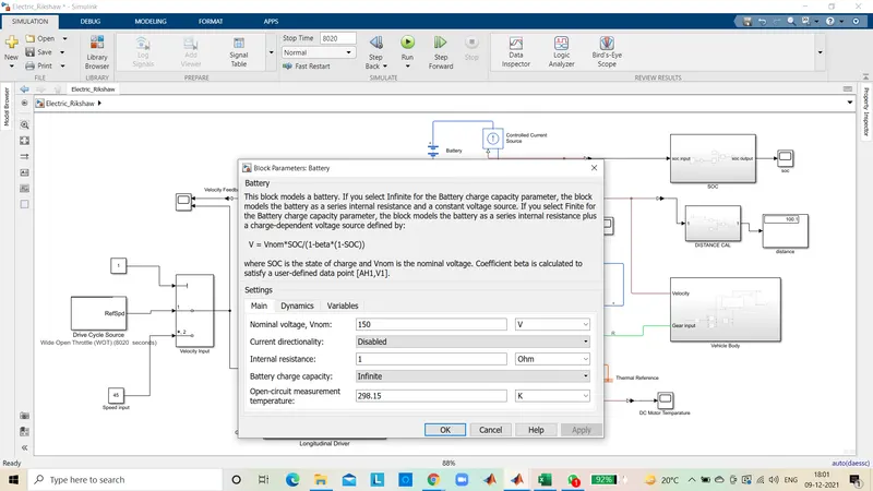
Specification of Battery :
Controlled Current Source :

The block represents an ideal current source that is powerful enough to maintain the specified current through it regardless of the voltage across it. The output current is where is the numerical value presented at the physical signal port.
SOC State of Charge :
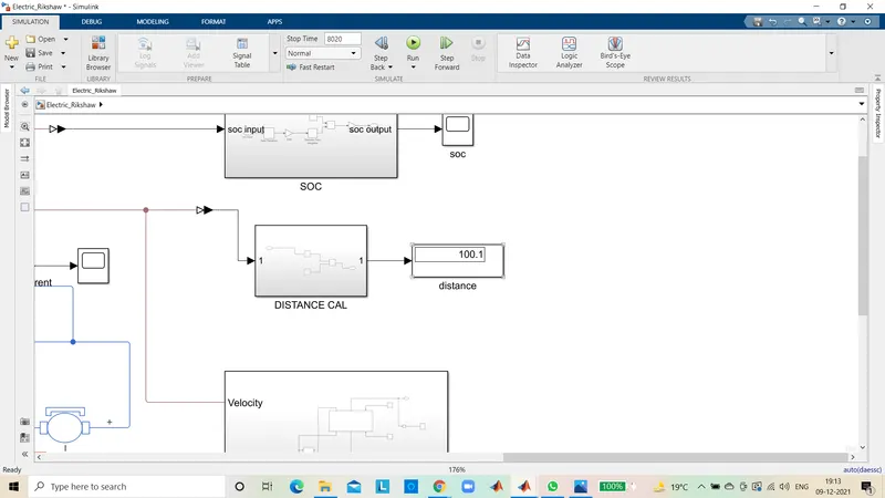
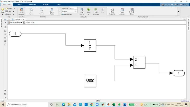
Distance calculation :
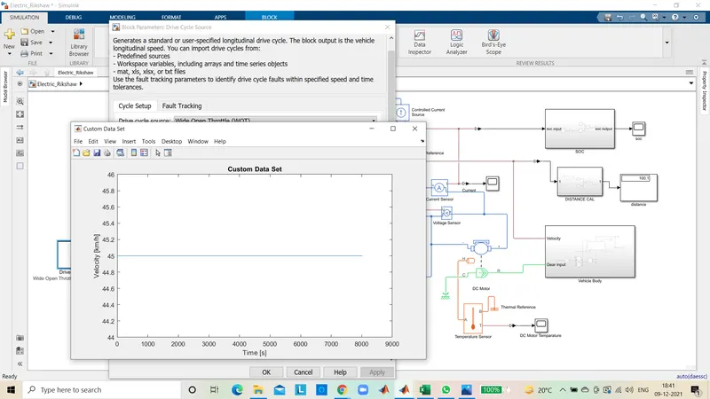
Drive cycle :
Longitudinal Driver :
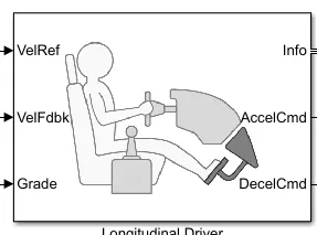
- It is a parametric longitudinal speed tracking controller for generating normalized Acceleration and Braking commands based on reference and feedback velocities.
- The VelFdbk port corresponds to the feedback velocity. The actual velocity output given by the vehicle body is connected here. By comparing the actual (feedback) velocity with the reference velocity, the driver block generates acceleration and braking signals in order to minimise the error between the two concerned velocities.
- Grade corresponds to the grade angle. For this simulation, no inclination is considered and hence, a constant block with value 1 is connected.
- Info gives the output for the bus signal for different block calculations like the difference in reference vehicle speed and vehicle speed, etc.
- AccelCmd & DecelCmd correspond to the acceleration and deceleration commands generated respectively and are connected to the corresponding parts of the Controlled PWM Voltage block.
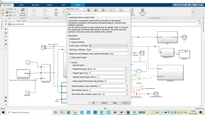
- Here, the selected control type is PLAccordingly, the block implements proportional-integral (P) control with tracking windup and feed-forward gains.
Excel of Input Data :
| Project Input | ||
| Vehicle body Parameters | ||
| Total Mass | 800 | kg |
| Frontal Area | 0.5 | m^2 |
| Air density | 1.25 | kg/m^3 |
| Drag coefficient | 0.01 | N |
| Tire Parameters | ||
| Rolling radius | 0.2 | m |
| Gear Parameters | ||
| Gear ratio | 2 | |
| Motor Parameters | ||
| No - load speed | 5000 | rpm |
| Rated speed | 4000 | rpm |
| Rated Load | 20 | kW |
| Rated DC supply | 150 | V |
| Thermal mass | 20000 | J/K |
| H-Bridge Parameters | ||
| Enable threshold voltage | 2.5 | V |
| PWM signal amplitude | 5 | V |
| Reverse threshold voltage | 0.1 | V |
| Braking threshold voltage | 0.001 | V |
| Output voltage amplitude | 150 | V |
| Total Bridge on resistance | 0.01 | ohm |
| Freewheeling diode resistance | 0.05 | ohm |
| Thermal mass | 20000 | J/K |
| Controlled PWM Voltage | ||
| PWM freequency | 1000 | Hz |
| Output voltage amplitude | 150 | V |
| Battery | 150 | V |
| Velocity | 45 | km/h |
| Distance | 100 | Km |
Results :
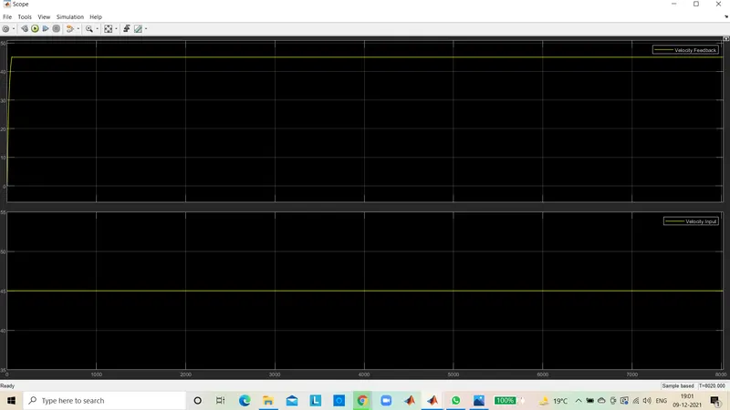
Velocity feed back :
Soc :
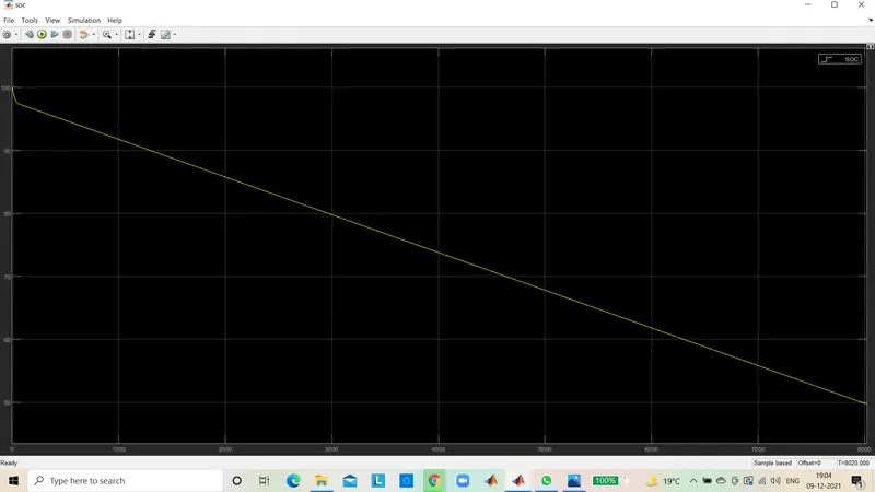
In WOT drive cycle after 8200 secs the battery capacity was still 49%. The above graph shows that remaining charge in the battery in terms of percentage after covering 100.1 km of distance.
DC motor Temparature :
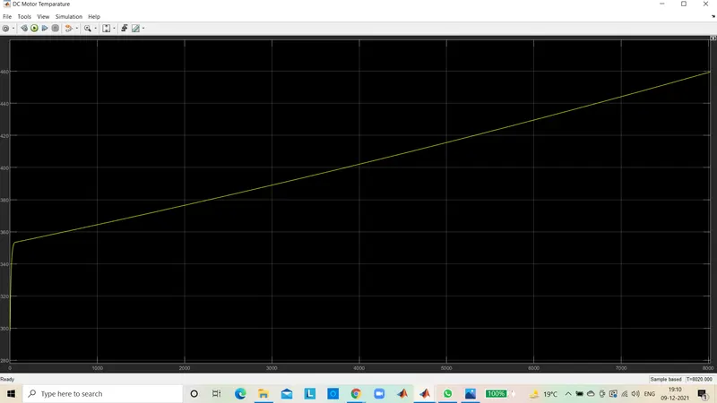
As we already know as vehicle starts to running then temparature also increases in motor.
H - Bridge temparature :
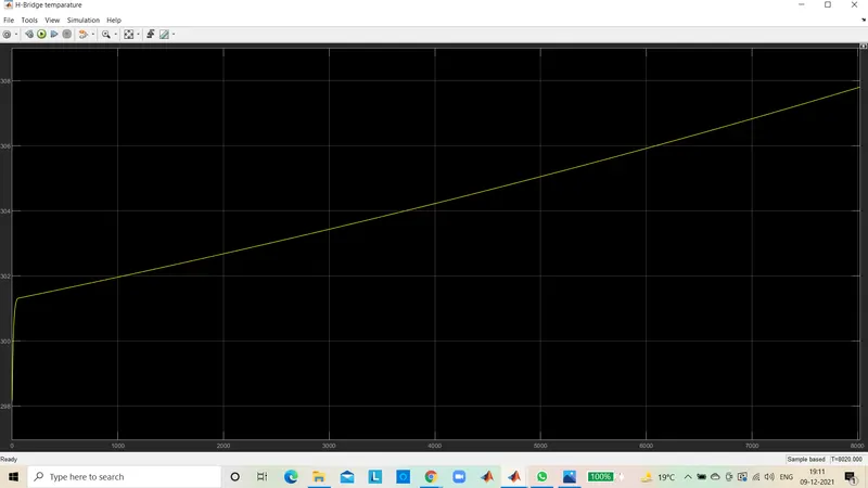
Distance : I given the above input detailes see the output at the speed of 45 km travelling 100 km distance taken 8200 secs. See the results below,