Final Project: Electric Rickshaw modelling
AIM
To create a detailed MATLAB model of an electric rickshaw (three wheel passenger vehicle) as per details below:
Rear wheels driven by PM brushed type motor
Assume efficiency points of motor controller and motor
Make an excel sheet of all input and assumed data
Results: For any three standard driving cycles show energy consumption, temperature rise of motor and controller for 100 km constant speed driving at 45 kmph.
SOLUTION
The adoption of electric vehicles (EVs) has been propelled with the objective of reducing the pollution and improving the fuel consumption.
In India, the NITI Aayog has charted out a plan of fully progressing towards EVs by 2030, which in turn reduces the CO2 emission by 37% and the energy demand by 64%.
The environmental factors favour the choice of pure EVs in urban India.
Of the different means of road transport available in urban India, the most preferred is the threewheeled vehicle namely auto rickshaw.
The conversion of this vehicle into a pure EV generates a lot of interest and necessitates a comprehensive analysis of various factors involved in the design and development of EVs to put forth new and efficient technologies
The energy storage system (ESS) forms the core of the pure EV, and batteries are the most widely used ESSs. However, a pure EV employing battery energy storage system (BESS) suffers from drawbacks like limited driving range, reduced battery life and low power density.
To overcome the above drawbacks, researchers have proposed the integration of ESSs. Ultracapacitors (UCs) and fuel cells are the most widely preferred storage system apart from battery for EV applications.
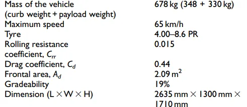
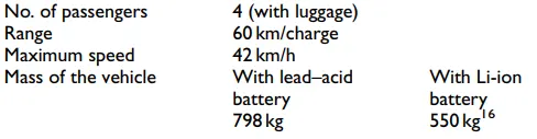
This work explores the concept of hybridizing battery and UC for a three-wheeled light electric vehicle (LEV). The specifications of the Bajaj RE three-wheeler have been considered for the analysis. The technical specifications of the conventional ICE-based three-wheeler is given below.
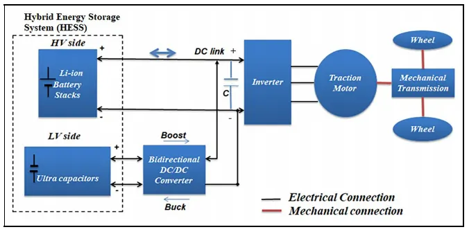
The block diagram of the electric drive system for the LEV considered in this work with dual ESSs (battery and UC) isalso shown below. The system employs a semi-active parallel configuration for interfacing battery and UC. Here, the battery acts as a main source, while the UC acts as an auxiliary source. In this configuration, the main source is directly connected to the DC link to maintain constant DC link voltage, and the auxiliary source is connected through a power electronic interface (PEI). This necessitates a highly efficient bi-directional DC/DC converter as an
interface between the ESS.
Specifications of an auto-rikshaw which is operated by ICE
Block diagram of a Light electric vehicle - Auto-rikshaw
It is important to study about the different forces acting on a vehicle according to which one could design system with proper power requirements. Frr is the rolling resistance force, Fad is the aerodynamic drag, Fhc is the hill climbing force, Fla is the
linear acceleration force and Fva is the rotational acceleration force are the forces usually act on a vehicle. The force required to drive the vehicle be the tractive force . Ft = Frr + Fad + Fhc +Fla +Fva Where Ft be tractive force.
The power requested during constant speed operation should be provided by the main energy source, Li-ion battery. The electrical energy from battery is lined with motor windings which intern causes rotation of rotor which is connected to the wheels through shaft arrangements.
One must design a battery and motor for an EV with high power which could overcome the forces mentioned earlier.
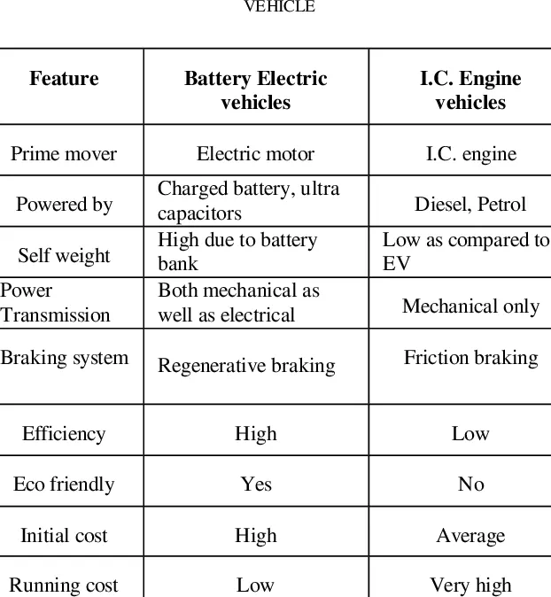
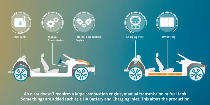
General difference between EV and ICE driven vehicles
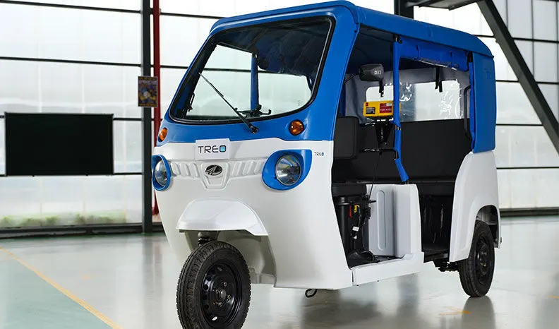
Lithium-ion electric three-wheelers – Treo electric auto and Treo Yaari electric rickshaw.
ADVANTAGES
Since the vehicle does not require power from a fuel or burning, there is not any emission from tail pipe.
The lithium ion battery has a life psan of 5 years making the system maintenance zero.
Like all the other electric vehicles , the treo comes with cloud based app control.
With a top speed of up to 45 KMPH (24.5 kmph for Treo Yaari), the stylish, modular Treo is apt for short to medium distance travels, perfect for daily commute. The Treo also has a certified range of 170 km (typical range of 10km) per charge, making it possible for multiple passenger transportation.
Treo's unique space frame design keeps pressure on impact distributed, so that passengers and the vehicle are both safe. The in-built rear crash guard also protects passengers from possible impact from behind. The frame also comes with best-in-class torsional rigidity and bending stiffness. It has an IP 65 rated battery box which ensures that the battery is safe from damage.
MATLAB model of an electric rickshaw
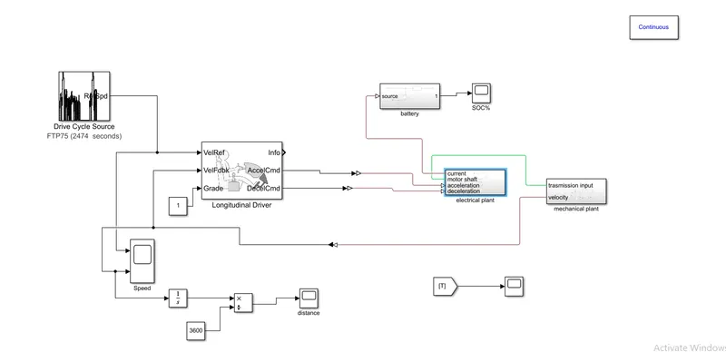
The above plant represents working of electric rickshaw.
Longitudinal driver block is used. It is a parametric longitudinal speed tracking controller for generating normalized acceleration and braking commands based on reference and feedback velocities.
Use the external actions to input signals that can disable, hold, or override the closed-loop commands determined by the block. The block uses this priority for the input commands: disable, hold, override.
Three subsystems are formed, electrical , mechanical and battery plants. These systems form the base for an EV in real time.
Electrical plant
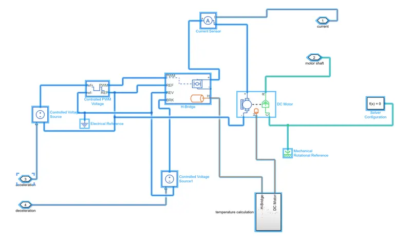
Controlled PWM voltage: This block creates a Pulse-Width Modulated (PWM) voltage across the PWM and REF ports
Controlled voltage block : The block represents an ideal voltage source that is powerful enough to maintain the specified voltage at its output regardless of the current passing through it. The output voltage is V = Vs, where Vs is the numerical value presented at the physical signal port.
H bridge :
This block represents an H-bridge motor drive. The block can be driven by the Controlled PWM Voltage block in PWM or Averaged mode. In PWM mode, the motor is powered if the PWM port voltage is above the Enable threshold voltage. In Averaged mode, the PWM port voltage divided by the PWM signal amplitude parameter defines the ratio of the on-time to the PWM period. Using this ratio and assumptions about the load, the block applies an average voltage to the load that achieves the correct average load current. The Simulation mode parameter value must be the same for the Controlled PWM Voltage and H-Bridge blocks.
If the REV port voltage is greater than the Reverse threshold voltage, then the output voltage polarity is reversed. If the BRK port voltage is greater than the Braking threshold voltage, then the output terminals are short circuited via one bridge arm in series with the parallel combination of a second bridge arm and a freewheeling diode. Voltages at ports PWM, REV and BRK are defined relative to the REF port.
If exposing the power supply connections, the block only supports PWM mode.
DC motor :
This block represents the electrical and torque characteristics of a DC motor.
The block assumes that no electromagnetic energy is lost, and hence the back-emf and torque constants have the same numerical value when in SI units. Motor parameters can either be specified directly, or derived from no-load speed and stall torque. If no information is available on armature inductance, this parameter can be set to some small non-zero value.
When a positive current flows from the electrical + to - ports, a positive torque acts from the mechanical C to R ports. Motor torque direction can be changed by altering the sign of the back-emf or torque constants.
Current sensor :
The block represents an ideal current sensor, that is, a device that converts current measured in any electrical branch into a physical signal proportional to the current.
PMC : Physical Modeling Connection Port block for subsystems.
Electrical and mechanical references : Electrical reference port. A model must contain at least one electrical reference port (electrical ground).
This block represents a mechanical rotational reference point, that is, a frame or a ground. Use it to connect mechanical rotational ports that are rigidly affixed to the frame (ground).
Another subssytem is created within this for calculating temperature.
Temperature sensor :
This block measures temperature in a thermal network. There is no heat flow through the sensor. The physical signal port T reports the temperature difference across the sensor. The measurement is positive when the temperature at port A is greater than the temperature at port B.
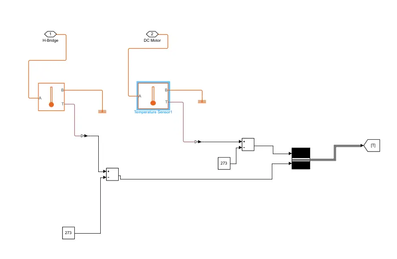
Other blocks are used here are constant block which is used for generating an input value that is constant.
Next Subtract block used for addition adn subtraction.
A bus creater which creates a bus from its inputs.
A goto block ,send signals to From blocks that have the specified tag and a thermal reference.
Vehicle body dynamics/mechanical plant
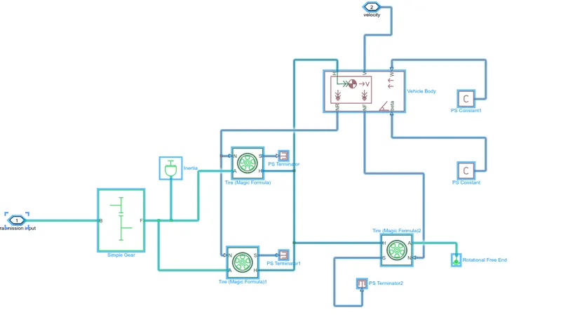
Simple gear : Represents a fixed-ratio gear or gear box. No inertia or compliance is modeled in this block. You can optionally include gear meshing and viscous bearing losses.
Connections B (base) and F (follower) are mechanical rotational conserving ports. Specify the relation between base and follower rotation directions with the Output shaft rotates parameter. Optionally include thermal effects and expose thermal conserving port H by setting Friction model to a temperature-dependent setting.
Tire :
Represents the longitudinal behavior of a highway tire characterized by the tire Magic Formula. The block is built from Tire-Road Interaction (Magic Formula) and Simscape Foundation Library Wheel and Axle blocks. Optionally, the effects of tire inertia, stiffness, and damping can be included.
Connection A is the mechanical rotational conserving port for the wheel axle. Connection H is the mechanical translational conserving port for the wheel hub through which the thrust developed by the tire is applied to the vehicle. Connection N is a physical signal input port that applies the normal force acting on the tire. The force is considered positive if it acts downwards. Connection S is a physical signal output port that reports the tire slip. Optionally expose physical signal port M by setting Parameterize by to Physical signal Magic Formula coefficients. Physical signal port M accepts a four element vector corresponding to the B, C, D, and E Magic Formula coefficients.
Inertia : The block represents an ideal mechanical rotational inertia.
Vehicle body :
Represents a two-axle vehicle body in longitudinal motion. The block accounts for body mass, aerodynamic drag, road incline, and weight distribution between axles due to acceleration and road profile. The vehicle can have the same or a different number of wheels on each axle. Optionally include pitch and suspension dynamics or additional variable mass and inertia. The vehicle does not move vertically relative to the ground.
Connection H is the mechanical translational conserving port associated with the horizontal motion of the vehicle body. The resulting traction motion developed by tires should be connected to this port. Connections V, NF, and NR are physical signal output ports for vehicle velocity and front and rear normal wheel forces, respectively. Wheel forces are considered positive if acting downwards. Connections W and beta are physical signal input ports corresponding to headwind speed and road inclination angle, respectively. If variable mass is modeled, the physical signal input ports CG and M are exposed. CG accepts a two- element vector representing the x and y distance offsets from vehicle CG to additional load mass CG. M represents the additional mass. If both variable mass and pitch dynamics are included, the physical signal port J accepts the inertia of the additional mass about its own CG.
PS terminator : Use this block to terminate physical signal outputs.
Rotational free end : This block represents a mechanical rotational free end. Use it to allow a node to rotate freely without torque. This block can be used to optionally specify initial rotational velocity.
Battery
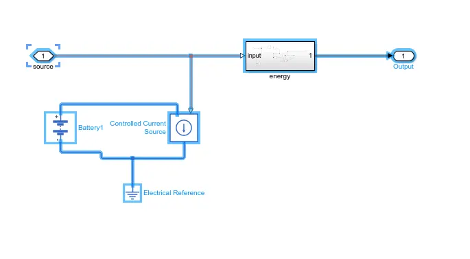
Energy calculation
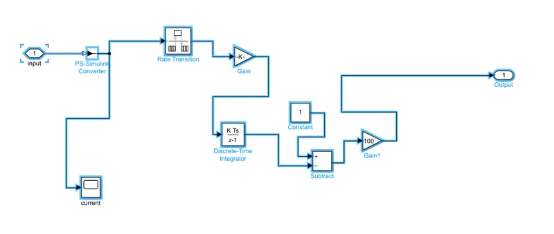
Various parameters are set and shown below.
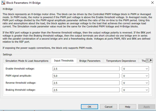
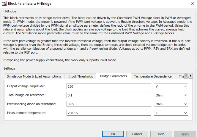
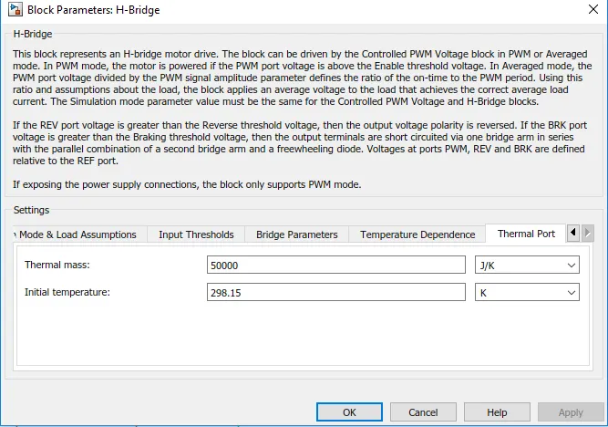
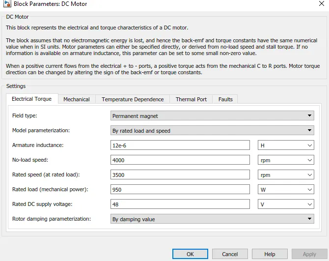
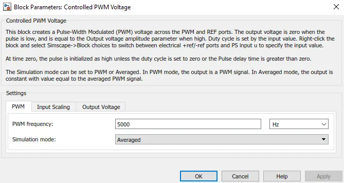
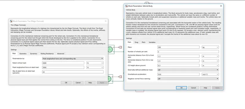
Now we have to set a required drive cycle and simulate the model.
FTP DRIVE CYCLE
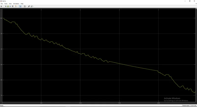
Simulation time-2474 seconds
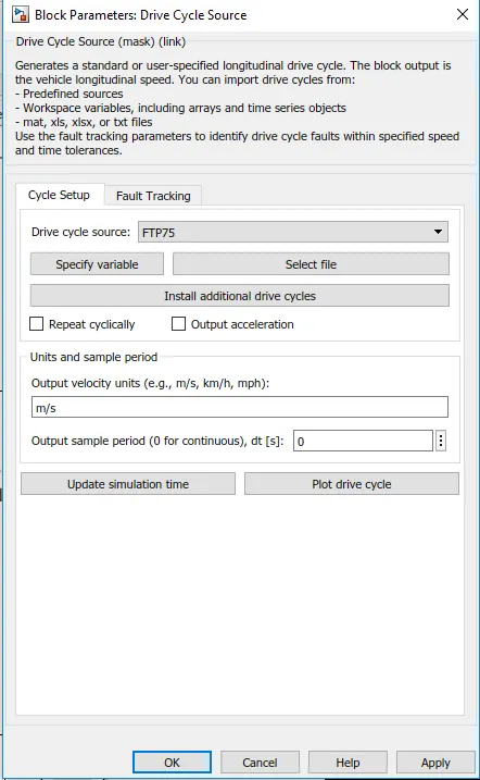
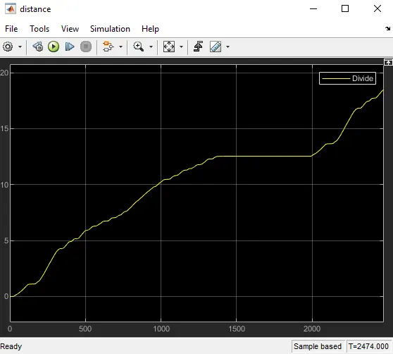
The distance is about 18-19km

This graph represents speed of vehicle designed according to the drive cycle data. There is a constant acceleration and deceleration and also vehicle comes to rest after 1500 sec
There is a power which is need to drive the vehicle. As we know battery gives the necessary power, the state of charge starts to decrease when we start to work on vehicle. During deceleration or breaking , the state of charge tends to increase a bit due to regenerative braking system.
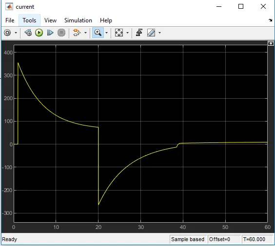
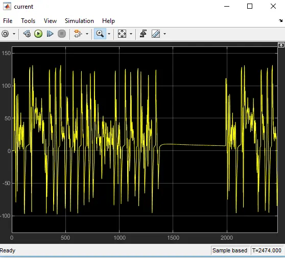
The graph shown below represents charging and discharging of battery with respect to current.
During discharge there is an increase in temperature of motor as well as battery.
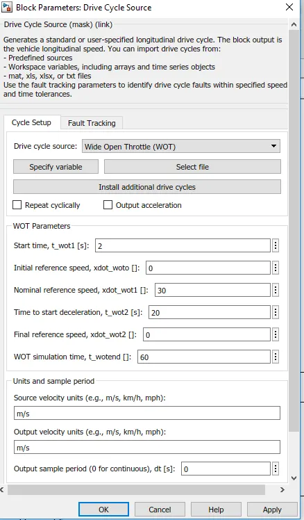
Wide open throttle drive cycle
This refers to the maximum-speed state of running the engine. In IC engines this could be related to fuel intake and outlet. Since the model taken is an EV , we relate with discharge of current.
Simulation time-60 seconds
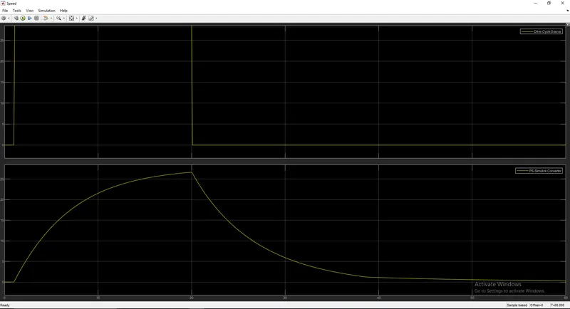
The graph shown below represents speed of this drive cycle.
For a particular the speed increases to maximum as throttling takes place and dops suddenly when we stop the process.
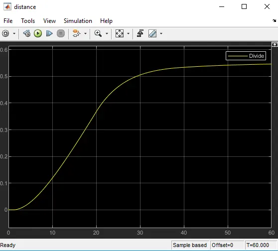
The distance covered is very low as our aim is to study about behaviour of system with respect to maximum throttling and not on a long run.
The state of charge drops suddenly while throttling as we need maximum energy to do the work
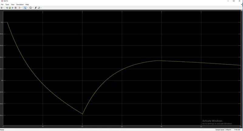
We could relate discharge of current with SOC