Final Project: Design of an Electric Vehicle
Q. Create a MATLAB model of electric car which uses a battery and a DC motor. Choose suitable blocks from Powertrain block set. Prepare a report about your model including following:
Objectives:
1. System level configurations
2. Model parameters
3. Results
4. Conclusion
Solution:
Electric Vehicle:
An electric vehicle (EV) is a mode of transport which is powered by electricity. Unlike conventional vehicles that use a gasoline (petrol) or diesel-powered engine, electric cars and trucks use an electric motor powered by electricity from batteries or a fuel cell. A key advantage of EVs over other forms of transport is that they hold the potential to significantly reduce pollution by having zero exhaust emissions.
How does an electric vehicle work?
EVs have an electric motor instead of an internal combustion engine (ICE). The vehicle uses a large traction battery pack to power the motor and must be plugged in to a charging station or wall outlet to charge. Most EVs use lithium-ion batteries, which have higher energy density, longer life span and higher power than most other practical batteries.
There are three main types of EVs.
All-Electric Vehicles: All-electric vehicles, also called battery electric vehicles, have a battery that is charged by plugging the vehicle in to charging equipment. These vehicles always operate in all-electric mode and have typical driving ranges from 150 to 400 miles.
Plug-In Hybrid Electric Vehicles (PHEV): PHEVs are powered by an internal combustion engine and an electric motor that uses energy stored in a battery. PHEVs can operate in all-electric (or charge-depleting) mode. To enable operation in all-electric mode, PHEVs require a larger battery, which can be plugged in to an electric power source to charge. To support a driver’s typical daily travel needs, most PHEVs can travel between 20 and 40 miles on electricity alone, and then will operate solely on gasoline, similar to a conventional hybrid.
Hybrid Electric Vehicles (HEV): HEVs are powered by an internal combustion engine and one or more electric motors that uses energy stored in a battery. The vehicle is fuelled with gasoline to operate.
What are the benefits of electric vehicles?
EVs are an environmentally friendly alternative to petrol or diesel cars as they generate much less air pollution, releasing no exhaust air pollutants. From wheel to wheel, EVS emit approximately 66% less carbon dioxide (CO2) compared with ICE-powered vehicles. The emissions associated with the electric drivetrain of EVs come from power plants generating electricity to charge the batteries – emissions can therefore be further reduced if renewable energy is used to recharged an EV. Noise pollution is also cut out due to the fact that an EV is nearly silent.
Running costs for fuel, maintenance and car tax are much lower for EVs. As company cars tend to travel further on a daily basis, the payback on the original purchase price is faster, making EVs particularly attractive for fleets.
One of the biggest benefits of introducing EVs to a business is the reduced refuelling costs, with electricity being far cheaper than fuel at the pump. Indeed, fuel costs can be as low as 2p per mile. For an annual mileage of around 10,000 miles per year, switching from a conventional to an electric car or van could save around £800 in fuel costs alone.
EVs are also a lot cheaper to maintain, mainly because they have a lot less moving parts than a conventional fossil-fuel powered car. For instance, there is relatively little servicing and no expensive exhaust systems, starter motors, fuel injection systems or radiators. Recent research has shown that several EV features can improve safety – EVs tend to have a lower centre of gravity that makes them less likely to roll over, for instance.
EV owners can gain additional monetary value from an EV through the implementation of vehicle-to-grid (V2G) technology, which provides demand-response services to the power grid. EVs can feed electricity into the grid when not in use through batteries during peak hours, and do most of their charging at night when there is unused generating capacity.
Main Components of Electric Vehicle:
· Traction battery pack: A traction battery pack is also known as an Electric vehicle battery (EVB). It powers the electric motors of an electric vehicle. The battery acts as an electrical storage system. It stores energy in the form of DC current. The range will be higher with increasing kW of the battery. The life and operation of the battery depending on its design. The lifetime of a traction battery pack is estimated to be 200,000 miles.
· DC-DC Converter: The traction battery pack delivers a constant voltage. But different components of the vehicle have different requirements. The DC-DC converter distributes the output power that is coming from the battery to a required level. It also provides the voltage required to charge the auxiliary battery.
· Electric motor: The electric traction motor is the main component of an electric vehicle. The motor converts electrical energy into kinetic energy. This energy rotates the wheels. An electric motor is the main component that differentiates an electric car from a conventional car. An important feature of an electric motor is the regenerative braking mechanism. This mechanism slows down the vehicle by converting its kinetic energy into another form and storing it for future use. There are basically two types of motors DC and AC motors.
· Power Inverter: It converts DC power from the batteries to AC power. It also converts the AC current generated during regenerative braking into a DC current. This is further used to recharge the batteries. The inverter can change the speed of the
· Charge Port: The charge port connects the electric vehicle to an external supply. It charges the battery pack. The charge port is sometimes located in the front or rear part of the vehicle
· On-board charger: The on-board charger is used to convert the AC supply received from the charge port to the DC supply. The on-board charger is located and installed inside the car. It monitors various battery characteristics and controls the current flowing inside the battery pack.
· Controller: The power electronics controller determines the working of an electric car. It performs the regulation of electrical energy from the batteries to the electric motors. The pedal set by the driver determines the speed of the vehicle and the frequency of variation of voltage that is input to the motor. It also controls the torque produced.
· Auxiliary batteries: Auxiliary batteries are the source of electrical energy for the accessories in electric vehicles. Without the main battery, the auxiliary batteries will continue to charge the car. It prevents the voltage drop, produced during engine start from affecting the electrical system.
· Thermal system(cooling): The thermal management system is responsible for maintaining an operating temperature for the main components of an electric vehicle such as an electric motor, controller, etc. It functions during charging as well to obtain maximum performance. It uses a combination of thermoelectric cooling, forced air cooling, and liquid cooling.
· Transmission: It is used to transfer the mechanical power from the electric motor to the wheels, through a gearbox. The advantage of electric cars is that they do not require multi-speed transmissions. The transmission efficiency should be high to avoid power loss.
There are 3 main EV charging speeds. They are,
· Slow: Typically rated up to 3kW, often used to charge overnight or at the workplace. Charging time is 8-10hours.
· Fast: Typically rated at either 7kW or 22kW. Tend to be installed in car parks, supermarkets, leisure centres and houses with off-street parking. Charging time is 3-4hours.
· Rapid: Typically rated from 43kW. Only compatible with EV's that have rapid charging capability. Charging time is 30-60minutes.
Electric Car:
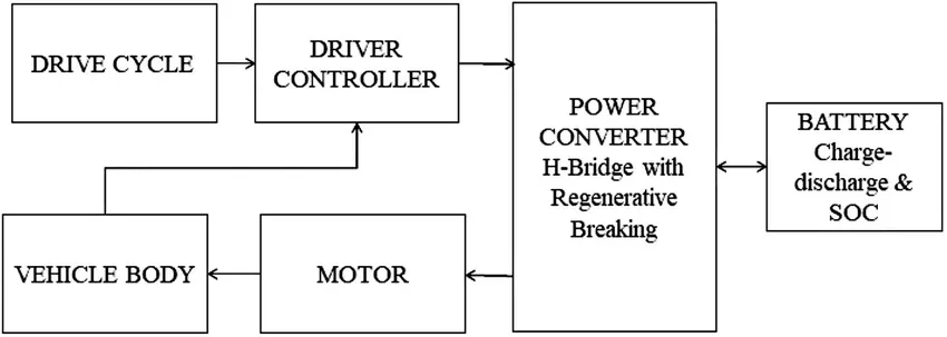
Block Diagram: The below figure shows the block diagram of Simulink model of an electric car. Drive cycle is used to input the data into the driver controller. The driver controller controls the acceleration and deceleration of the vehicle. Power converter which is a H-Bridge with regenerative braking, is used to drive the Dc motor. The battery block indicates the charging and discharging condition and the %of SOC (state of charge) variations with respect to the drive cycle. The motor block and battery block is connected to the power converter block which indicates that, power converter which plays a vital role in the controlling and converting the electrical energy. Motor block indicates the motor positioning and type of motor we are using, here the permanent magnet DC motor is used. The vehicle body block indicates the mechanical structure of an electric car like wheels and their connections.
Simulink Model:
Blocks Used:
Drive cycle source: The Drive cycle source block generates a standard or user specified longitudinal drive cycle. FTP 75 drive cycle is used in the simulation.
Longitudinal Driver: A parametric longitudinal speed tracking controller for generating normalized acceleration and braking commands based on reference and feedback velocities. Based on reference and feedback velocities, the block generates normalized acceleration and braking command that can vary from 0 to 1. The input ports, velref is connected to the drive cycle source block for the reference velocity, VelFdbk port is a feedback port connected from the vehicle body gear. Grade is grounded. Info is connected to terminator block. AccelCmd is connected to the respective acceleration source and Decelcmd is connected to its respective deceleration source. In the Longitudinal block the control type is selected as PI, hence the block implements proportional-integral (PI) control with tracking windup and feed-forward gains.
gains.
Motor Controller Subsystem: Motor controller is a subsystem, controls the motor actions. It is connected in between the vehicle body and longitudinal block and also has connection with the battery. It plays a major role in controlling the motor speed, charge and discharge the motor according to the motoring and braking conditions. This subsystem consists of Controlled Voltage Source, Controlled PWM Voltage, H-Bridge, DC Motor, Current sensor, Voltage sensor, Solver configuration, Electrical and Mechanical Rotational Reference, Connection port and Out port.
Motor controller subsystem consists of the following blocks,,
Controlled voltage source: The Controlled Voltage Source block represents an ideal voltage source that is powerful enough to maintain the specified voltage at its output regardless of the current passing through it. The output voltage is V = Vs, where Vs is the numerical value presented at the physical signal port. There are 2 controlled voltage source blocks used in the subsystem. The first one is connected to the +ve Ref of controlled PWM voltage and ground. The physical port is connected to the connection port2 which indicates the acceleration. This port is connected to the Accelcmd port of longitudinal driver. The second one is connected break port of H-Bridge and ground. The physical port is connected to the connection port3 which indicates the deceleration. This port is connected to the Decelcmd port of longitudinal driver.
Controlled PWM Voltage: This block creates a Pulse-Width Modulated (PWM) voltage across the PWM and REF ports. The output voltage is zero when the pulse is low, and is equal to the Output voltage amplitude parameter when high. Duty cycle is set by the input value. The Simulation mode can be set to PWM or Averaged. In PWM mode, the output is a PWM signal. In Averaged mode, the output is constant with value equal to the averaged PWM signal. The averaged simulation mode is selected for the Electric car model. The +ref port is connected to the controlled voltage source, PWM port is connected to the H-Bridge PWM port. -ve ref and REF ports are connected to the common ground (REF port is also connected to the REF port of H-Bridge)
H-Bridge: The H-Bridge block can be driven by the Controlled PWM Voltage block in PWM or Averaged mode. In PWM mode, the motor is powered if the PWM port voltage is above the Enable threshold voltage. In Averaged mode, the PWM port voltage divided by the PWM signal amplitude parameter defines the ratio of the on-time to the PWM period. Using this ratio and assumptions about the load, the block applies an average voltage to the load that achieves the correct average load current. The Simulation mode parameter value must be the same for the Controlled PWM Voltage and H-Bridge blocks. If the REV port voltage is greater than the Reverse threshold voltage, then the output voltage polarity is reversed. If the BRK port voltage is greater than the Braking threshold voltage, then the output terminals are short circuited via one bridge arm in series with the parallel combination of a second bridge arm and a freewheeling diode. Voltages at ports PWM, REV and BRK are defined relative to the REF port. Where PWM and REF ports are connected to the respective ports of controlled PWM voltage block. REV port is connected with the REF port to the common ground. BRK port is connected to the positive terminal of the controlled voltage source to indicate the deceleration during the braking period. The output +ve and -ve ports are connected to the DC motor along with the current sensor.
Current Sensor: This block represents an ideal current sensor, that is, a device that converts current measured in any electrical branch into a physical signal proportional to the current. Connections + and - are conserving electrical ports through which the sensor is inserted into the circuit (between H-Bridge and DC Motor). Connection I is a physical signal port that outputs current value.
Voltage Sensor: This block represents an ideal voltage sensor, that is, a device that converts voltage measured between any electrical connections into a physical signal proportional to the voltage. Connections + and - are conserving electrical ports through which the sensor is connected to the circuit. Connection V is a physical signal port that outputs voltage value.
DC Motor: This block represents the electrical and torque characteristics of a DC motor. The block assumes that no electromagnetic energy is lost, and hence the back-emf and torque constants have the same numerical value when in SI units. Motor parameters can either be specified directly, or derived from no-load speed and stall torque. If no information is available on armature inductance, this parameter can be set to some small non-zero value. When a positive current flows from the electrical + to - ports, a positive torque acts from the mechanical C to R ports. Motor torque direction can be changed by altering the sign of the back-emf or torque constants. The +ve and -ve connections are electrical which are connected to the H-Bridge and C, R are the mechanical ports which are connected to the respective mechanical gear. We have taken a connection port across it to connect it further with the mechanical system. Taking the connection port4 as Shaft.
Solver configuration: Each physical network represented by a connected simscape block diagram requires solver settings information for simulation. It specifies the solver parameters that the model needs before simulation. The block has one conserving port and can be added anywhere on a physical network circuit by creating a branching point and connecting it to the only port of the solver configuration block.
PS-Simulink Converter: This block converts the input Physical Signal to a Simulink output signal.
Electrical Reference: The electrical reference block represents an electrical ground. This block has only one electrical conserving port. Electrical conserving ports of all the block that are directly connected to ground must be connected to an electrical reference block.
Mechanical rotational reference: The mechanical rotational reference block represents a reference point for mechanical rotational ports. Rotational parts are rigidly clamped to the ground must be connected to a mechanical rotational reference block.
Connection Port: The Connection Port block transfers a physical connection or signal across subsystem boundaries. A subsystem needs a Connection Port block for each physical connection line that crosses its boundary. We can manually place a Connection Port block inside a subsystem, or Simulink can automatically insert a Connection Port block when a subsystem is created within an existing network.
Out port: This block links signals from a system to a destination outside of the system. It can connect signals flowing from a subsystem to other parts of the model.
Battery Subsystem: The battery subsystem includes a battery to supply the electrical energy to the motor to run efficiently. And a circuit to calculate the SOC (State of charge) variations. This sub system consists of Battery, controlled current Source, Rate Transmission, Gain block, Discrete time integrator, constant, Add block, Connection port and out port.
Battery: The battery block represents a simple battery model. The positive and negative terminals of the battery is connected to the controlled current source and to the ground which is connected to electrical reference block respectively.
Controlled Current Source: This block represents an ideal current source that is powerful enough to maintain the specified current through it regardless of the voltage across it. The output current is I = Is, where Is is the numerical value presented at the physical signal port. The physical port is connected to rate transition block by using PS-Simulink converter. The connection port1 taken across it is connected to the DC motor controller current connection port1.
Rate Transmission: The Rate Transition block transfers data from the output of a block operating at one rate to the input of a block operating at a different rate. This block parameter is used to trade data integrity and deterministic transfer for faster response or lower memory requirements. It transfers data from the battery current to calculate the SOC of the battery in our model.
Gain: The gain block multiplies that input by a constant value. Two gain blocks are used in the model.
Discrete time integrator: The discrete time integrator block used in place of an integrator block to create a purely discrete model. With this block, the initial conditions, input gain value, upper and lower limits on the integral are defined.
Constant Block: This block is used to create a constant value
Add Block: The add block is used to add the input values and give the result through its output. The output of discrete time integrator block and constant value is added in this block.
Connection port1 is connected to the current of connection port1 in the motor controller subsystem. And out port %SOC is connected to the scope block to observe the variation in state of charge which is the ratio of current charge to rated battery capacity.
Transmission Subsystem: The Transmission subsystem consists of four wheels which are connected to the vehicle body of the electric car. This subsystem shows the mechanical action between the wheels and gear. This subsystem consists of 4 Tire (magic formula), Vehicle body, simple gear, PS Constant, Connection port.
Tire (magic formula): Represents the longitudinal behaviour of a highway tire characterized by the tire Magic Formula. The block is built from Tire-Road Interaction (Magic Formula) and Simscape Foundation Library Wheel and Axle blocks. The block can model tire dynamics under constant or variable pavement conditions. The longitudinal direction of the tire is same as its direction of motion as it rolls on pavement. This block models the tire as a rigid wheel-tire combination in contact with the road and subject to slip. When torque is applied to the wheel axle, the tire pushes on the ground and transfers the resulting reaction as a force back on the wheel. This action pushes the wheel forward or backward. Below are the ports of this block,
N - It is a physical signal input port associated with the normal force acting on the tire.
A - It is a mechanical rotational port associated with the axle that the tire sits on.
S - It is a physical signal output port associated with the relative slip between the tire and road.
H - It is a mechanical translational port associated with the wheel hub that transmits the thrust generated by the tire to the remainder of the vehicle.
In the Simulink model of an electric car 4 tires are required. The N port of the left side two tires are connected together to the NR port of the vehicle body and N port of the right side two tires are connected together to the NF port of the vehicle body, which indicates the rear and front wheels respectively. All the H ports of the 4 tires are connected to the H port of the vehicle body. The A ports of left side tires are connected in the same manner the right side tires A ports are also connected. Simple gear block is connected to the common A port of the left side tires.
Vehicle Body: This block Represents a two-axle vehicle body in longitudinal motion. The block accounts for body mass, aerodynamic drag, road incline, and weight distribution between axles due to acceleration and road profile. The vehicle can have the same or a different number of wheels on each axle. Optionally include pitch and suspension dynamics or additional variable mass and inertia. The vehicle does not move vertically relative to the ground. The ports of vehicle body are,
NR - It is a physical signal output port for normal force on the rear axle. Wheel forces are considered positive if acting downwards.
NF - It is a physical signal output port for normal force on the front axle. Wheel forces are considered positive if acting downwards.
Beta - It is a physical input port for road incline angle.
H - It is a conserving port associated with the horizontal motion of the vehicle body. Tire traction motion is connected to this port.
V - It is a physical signal output for vehicle longitudinal velocity.
W - It is a physical signal input port for headwind speed.
NR is connected to the left side tire N ports and NF is connected to the right side tires N ports. H is connected common to all the tires H ports. Beta and W is connected to PS constant blocks. V is connected connection port2 which is connected to longitudinal driver block as the feedback velocity and scope.
PS Constant: The PS Constant block generates a physical signal of a constant value. This block has only one output port which is a physical signal. In this model two PS Constant blocks are used, which are connected across the W and Beta ports of the vehicle.
Simple gear: The simple gear block represents a gearbox that constrains the connected driveline axes of the base gear B, and the follower gear f, to co-rotate with a fixed ratio that we specified. We can choose the follower axis rotation, which is either in the same or opposite direction as the base axis. If they rotate in same direction, the angular velocity of the follower and angular velocity of the base have the same sign. If they rotate in opposite directions, the angular velocities have opposite signs. In our model we are considering the same direction as base axis.
B - It is a rotational mechanical conserving port associated with the base, or input shaft.
F - It is also a rotational mechanical port associated with the follower, or output shaft.
The Port F is connected to the common connection of rear tires A port. And the port B is connected to a connection port as gear which is connected at the shaft connection port in the motor controller subsystem. Which means this gear port is connected to the DC motor R port.
The feedback velocity is integrated with respect to time to get the total distance covered from initial position to final position. The distance is divided by 1000 to get in kilo meters.
The simulation is run for 2474 seconds and the results are obtained on scope.
The drive cycle, % SOC, Voltage, current, longitudinal velocity and distance covered obtained from different sub systems are plotted with respect to time in the scope.
Result:
Scope screenshot:
1st plot shows the graph of drive cycle (FTP 75) and the 5th plot shows the graph of feedback velocity obtained from Vehicle body subsystem. The reference drive cycle and the feedback velocity similar, there is slight variation in the feedback velocity due to the real time road conditions.
The 2nd plot represents the %SOC of the battery and is obtained from the battery subsystem. From the graph it is clear that when the car is accelerating to high value the battery is discharging and when it is in decelerating condition the battery gets charged.
The 3rd plot represents the Voltage variations of the motor according to the car accelerating and decelerating conditions and is obtained from the Voltage port of Motor controller subsystem. The voltage sensor block is connected across the motor to observe these variations. The voltage variation can be compared with the feedback velocity and the voltage increases if the vehicle is accelerating, voltage decreases when the vehicle is decelerating and voltage is constant when the car is maintaining its velocity at certain point with respect to time
The 4th plot represents the current variations of the motor according to the drive cycle obtained from the current port of the motor controller subsystem. The current sensor which is connected in between the H-Bridge and DC motor senses the current changes and they are plotted through the scope block. The variation in motor controller current can be compared with the drive cycle. Current is increasing according to acceleration and decreasing according to the deceleration. And if the vehicle is maintaining a constant acceleration or deceleration then the current is also maintaining its range according to it.
The 6th plot represents the distance travelled by the electric car during the simulation.
Conclusion:
MATLAB model of and electric car using a battery and a DC motor is developed and simulated for 2474 second and the results are plotted. It is observed that the vehicle travels for 22.4 KMs in 2474 second with FTP 75 drive cycle. The performance of the electric car depends on the drive cycle. The % SOC of battery has reduced to 88.91% by the end of simulation.