Final Project: Design of an Electric Vehicle
CONTENT:
- OBJECTIVE
- THEORY
- SIMULINK BLOCKS WITH PARAMETERS
- SIMULINK MODEL EXPLANATION
- RESULT OBSERVATION
- PROS AND CONS OF MODELING EV IN MATLAB/SIMULINK
A. OBJECTIVE:
- Here my goal is to deliver a proper Matlab/Simulink model of an electric vehicle that uses a battery and a DC motor with appropriate model parameters
- Model explanation
- Simulink blocks used in the model
- Results and conclusions.
B. THEORY:
What is an electric vehicle?
An EV, or electric vehicle, is a type of automobile that is powered by electricity instead of gasoline or diesel fuel. EVs use one or more electric motors to drive the wheels, and the electricity is stored in rechargeable batteries. EVs offer several advantages over traditional gasoline-powered vehicles, including lower emissions, reduced fuel costs, and improved energy efficiency. However, they also have some limitations, such as limited driving range, longer charging times, and higher upfront costs.

The above display is a showcase of the fastest electric vehicle (EV) in the world to date the Rimac Nevera, which is manufactured by Croatian company Rimac Automobili. The Nevera can accelerate from 0 to 60 miles per hour in just 1.85 seconds and has a top speed of 258 miles per hour. It is powered by a 1,914 horsepower electric motor and has a range of around 340 miles on a single charge. It is also a fully electric vehicle.
Why electric vehicles?
Several theories explain the technology and impact of electric vehicles:
-
Environmental benefits: One of the main reasons for the development of EVs is their potential to reduce greenhouse gas emissions and improve air quality. EVs have the potential to reduce carbon emissions, air pollution, and noise pollution, which could lead to improved health outcomes and a more sustainable environment.
-
Battery technology: The development of high-capacity, low-cost, and safe battery technology is a critical factor in the success of EVs. The range and performance of EVs are directly dependent on the capabilities of their batteries, and advances in battery technology could lead to more affordable, longer-range, and faster-charging EVs.
-
Infrastructure: The availability and accessibility of charging infrastructure are also critical factors for the widespread adoption of EVs.
-
Cost: The cost of EVs has traditionally been higher than that of traditional gasoline-powered vehicles, but this gap is narrowing as battery technology improves and economies of scale are achieved.
Overall, electric vehicles have the potential to play a significant role in the transition to a more sustainable and environmentally friendly transportation system. However, there are still challenges to overcome, such as battery technology, infrastructure, and market adoption, before EVs can achieve widespread adoption.
EV designing in this project :
The electric vehicle design-based model can be achieved in various methods, but it depends on the prospects of understanding the technology.
- Here I will try to achieve a complete model of EV with the help of Simulink with system-level configuration and mostly with default parameters predefined in the Matlab software.
- For advanced designing in 3D one can use CAD/CAM/CAE/CATIA or especially Solidworks, though this is not the goal of my project.
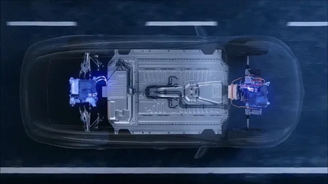
The above display is an example of a 3D modeling with textures/animation.
A complete EV with block diagram:
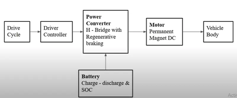
The below-attached block diagram is the primitive concept of my model.
C. SIMULINK BLOCKS WITH PARAMETERS:
The Simulink blocks used in this model can be divided into three types which are Electrical blocks, Mechanical blocks, simscape blocks,
- Vehicle Body
- Terminator
- Tire(Magic formulae)
- Inertia
- Simple gear
- Mechanical Rotational Reference
- DC motor
- Controlled PWM voltage
- H-Bridge
- Current sensor
- Controlled Voltage Source
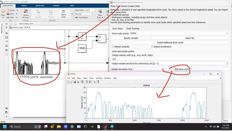
- Drive cycle source
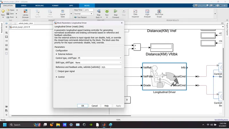
- Longitudinal Driver
- Constant
- Integrator
- Product
- Scope
- Display
- controlled current source
- Generic Battery Model
- Bus selector
- PowerGUI
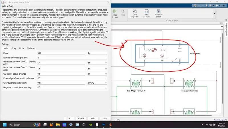
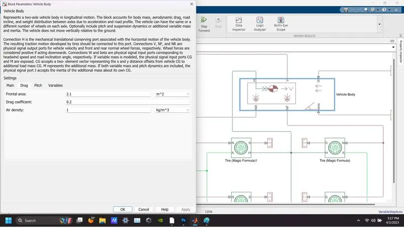
The parameters I used in the above blocks are listed below:
Vehicle Body:
Tire(Magic formulae):
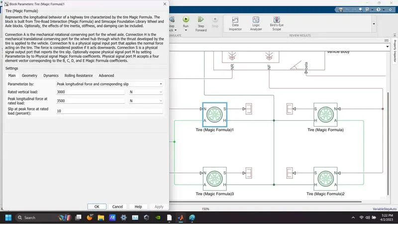
Simple gear:
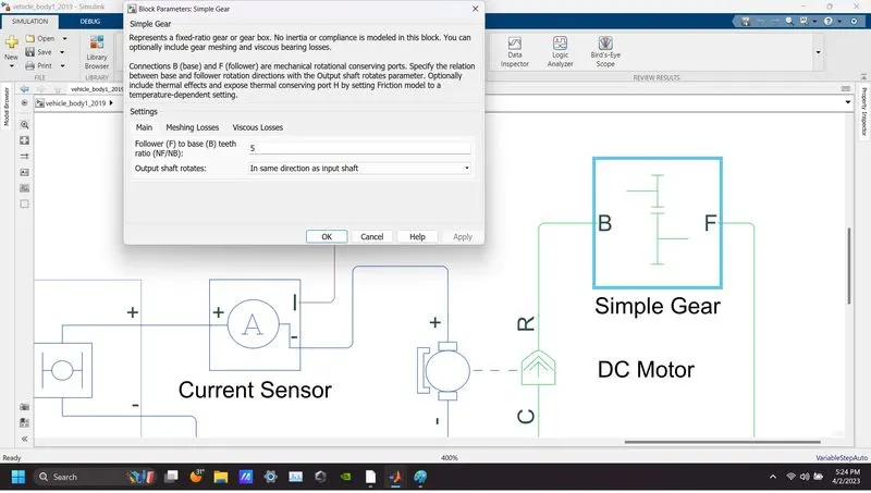
DC motor:
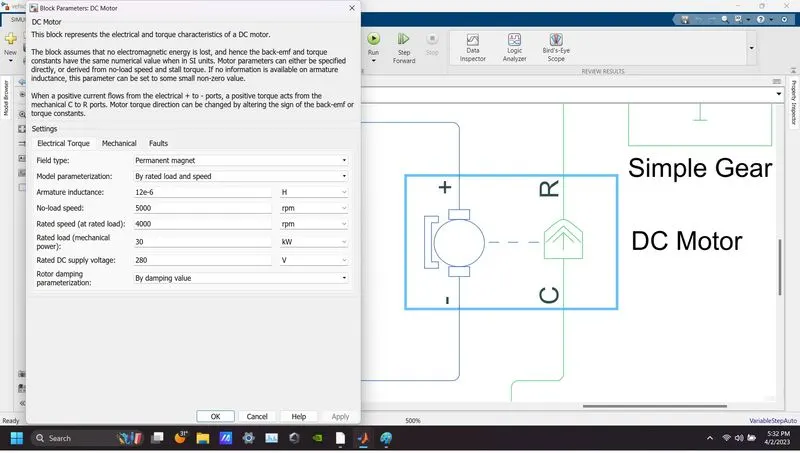
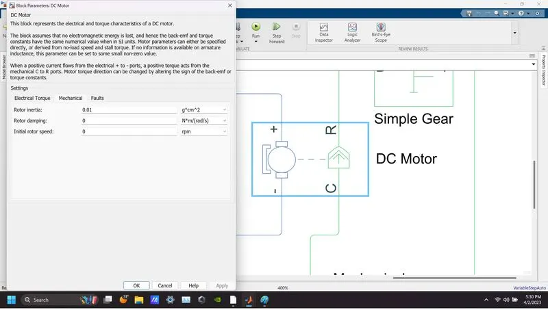
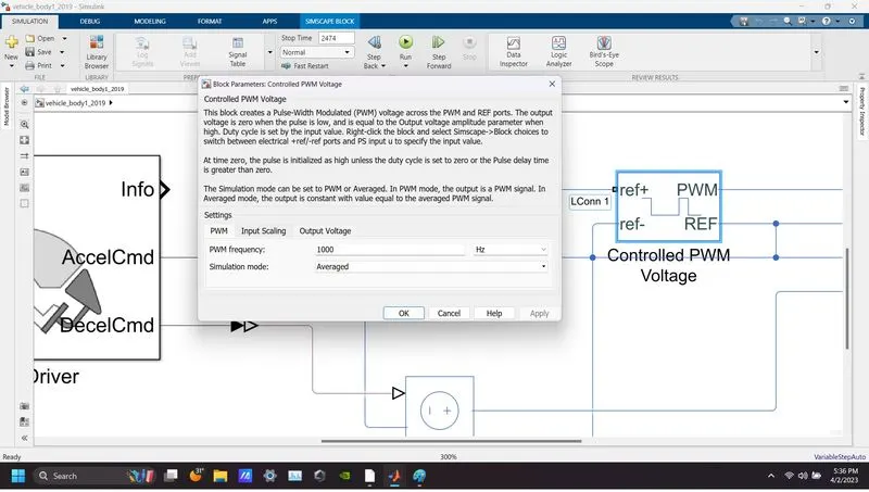
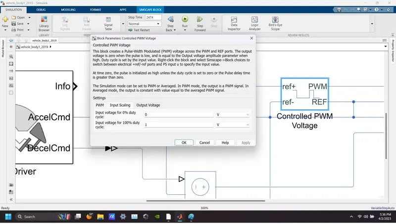
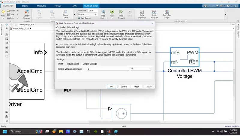
Controlled PWM volt:age:
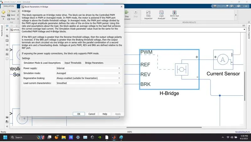
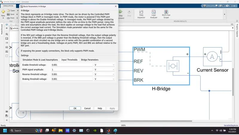
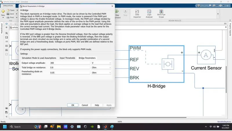
H-Bridge:
Drive cycle source:
Longitudinal Driver:
Generic Battery Model:
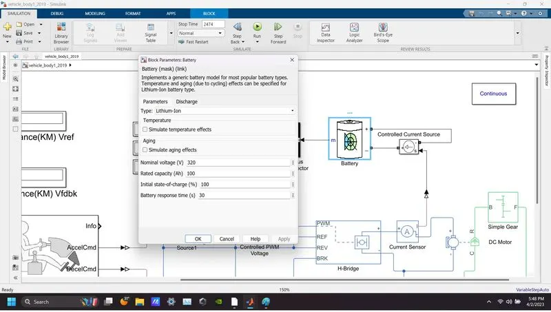
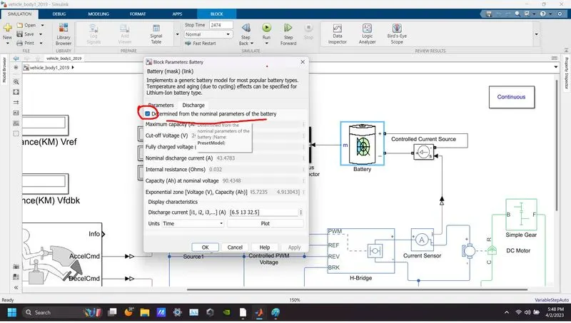
SIMULINK MODEL EXPLANATION:
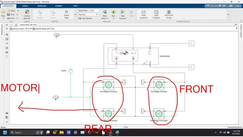
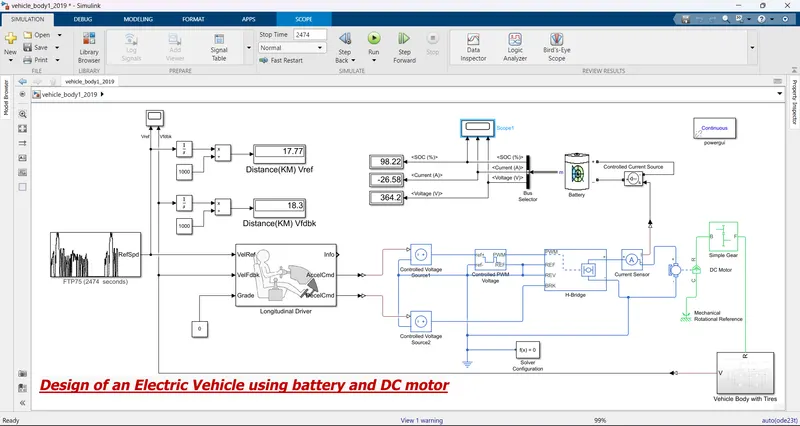
Step 1: I connected the vehicle body with 4 tires where the DC motor is connected to the rear wheel axle thus it makes a rear-wheel drive vehicle.
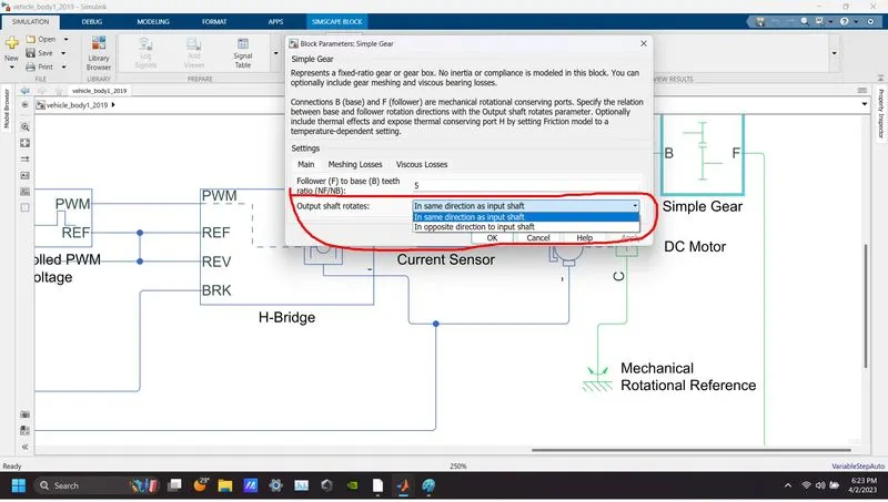
Step 2: Connect DC motor and gearbox (simple gear block) in series to the rear wheel axle and change the output shaft rotation in the same direction as the input shaft otherwise the car will drive backward which will be hilarious. Now, these are all the Mechanical parts of the car.
STEP3:
- Now I will connect the mechanical parts of the car to the electrical part which are controlled PWM voltage and H-bridge accordingly.
- In an electric vehicle (EV), the purpose of a controlled PWM voltage block is to regulate the voltage and current supplied to the motor controller. PWM stands for Pulse Width Modulation, which is a technique used to control the speed and torque of the electric motor. The controlled PWM voltage block typically consists of a DC/DC converter and a controller. The DC/DC converter converts the high-voltage DC power from the battery into a lower voltage that can be used by the motor controller. The controller then modulates the width of the voltage pulses supplied to the motor to control its speed and torque. By regulating the voltage and current supplied to the motor, the controlled PWM voltage block can improve the efficiency of the electric powertrain and extend the range of the vehicle. Additionally, it can help to protect the motor and other components from damage due to overloading or overvoltage.
- In an electric vehicle (EV), the purpose of an H-bridge block is to control the direction and speed of the electric motor. An H-bridge is an electronic circuit that allows the motor to be driven in both directions by changing the polarity of the voltage applied to it. The H-bridge block typically consists of four switches, usually, MOSFETs or IGBTs, arranged in a configuration that resembles the letter "H". The switches are controlled by a driver circuit that sends signals to turn them on or off, depending on the desired direction and speed of the motor.
- we need two controlled voltage blocks to connect directly to the acceleration and braking, in my case in the model one is connected to a positive i/p terminal of PWM voltage, and the other one is connected to braking in H-bridge.
- Last but not least connect all the negative terminals of the electrical blocks with the ground(electrical reference block) and use solver configuration.
STEP4: Need a driver for the vehicle which can be done by a longitudinal driver block that can control acceleration or braking if a reference velocity is provided to the model.
STEP5: The above-mentioned reference velocity can be provided with the help of the drive cycle source block or it can be done manually in Matlab workspace or excel sheet by providing the velocity of each sec.
STEP6: Connect a battery just to understand the relation of soc/battery voltage/ battery current with the drive cycle.
STEP 7: Use scope and display for a better understanding of the model.
RESULT OBSERVATION:
Below the attached picture is the final output of the model which is taken after simulating for 2472 sec.
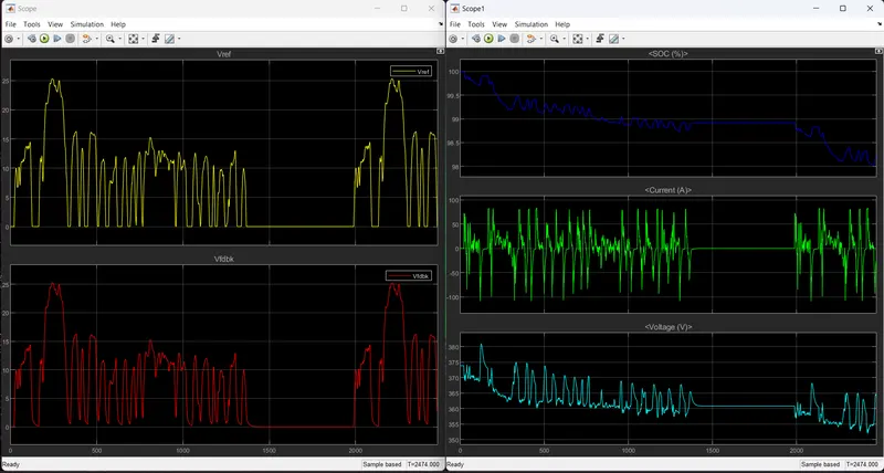
The below-attached picture consists of the result of the above model after simulating for 2474 sec, incase is unclear due to the lower quality of the image,
- Yellow is the reference voltage from the drive cycle source.
- Red is feedback voltage getting from the vehicle body.
- Blue is SOC (%) of Battery.
- Green is the charging or discharging current of the battery.
- cyan is the Voltage of the battery.
Gradability test:
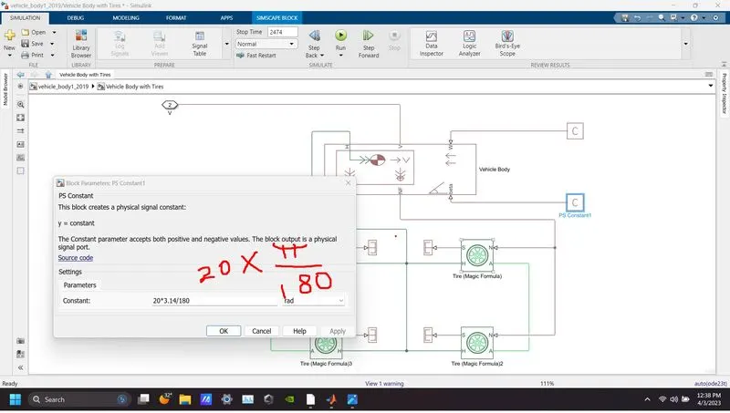
- To add greadibility in the model one has to convert the degree into radian first and add it to the vehicle body with the help of a ps constant block as I did in the above image.
- From the below table we can understand that by increasing the inclination angle we are increasing the hillclimbing force as a result the vehicle will be needing more tractive force to achieve the drive cycle set by the user as a result battery will start discharging at a much higher rate than the usual before and SOC and voltage will be reduced faster. At gradeability 20deg the car failed to achieve the Drive cycle set by the user as we can see SOC reached 0% already and in Simulink we can see that happens around 1910sec through the scope.
| Simulation Time | Distance covered according to Reference Velocity | Distance covered according to Feedback Velocity | Gradeability | SOC | Battery Voltage |
| FTP75(2474 sec) | 17.77Km | 18.3Km | 0 | 98.22% | 364.2 VDC |
| FTP75(2474 sec) | 17.77Km | 17.78Km | 5 | 65.33% | 345.1VDC |
| FTP75(2474 sec) | 17.77Km | 16.98Km | 10 | 32.87% | 336.8VDC |
| FTP75(2474 sec) | 17.77Km | 15.43Km | 15 | 0.9% | 228.7VDC |
| FTP75(2474 sec) | 17.77Km | 10.68Km | 20 | 0% | 0 VDC |
WOT test:
- WOT test evaluates a vehicle's maximum power and acceleration capability.
- In the below table we can observe that my vehicle can reach the highest 27.3m/s velocity if no hill climbing force is introduced.
- Higher hill climbing force lower the final speed of the vehicle.
| Simulation Time | Gradeability | max velocity(Vref) | max velocity(Vfdbk) |
| WOT(30 sec) | 0 | 30 | 27.3m/s |
| WOT(30 sec) | 5 | 30 | 22.1m/s |
| WOT(30 sec) | 10 | 30 | 16.9m/s |
| WOT(30 sec) | 15 | 30 | 11.7m/s |
| WOT(30 sec) | 20 | 30 | 6.5m/s |
CONCLUSION
- This model in Simulink is very primitive or basic level modeling and also I used mostly default parameters to get an appropriate output but if you use real-time parameters of a car (as an example TATA NEXON) the calculation is going to be much more complex.
- Distance covered according to reference velocity and feedback velocity is always different no matter what that is because if you follow the below image it can be observed according to reference velocity plots the car has stopped several times means speed was null in those scenarios but according to the feedback velocity my can never stop or reach the null speed that's why covered distance is always higher.
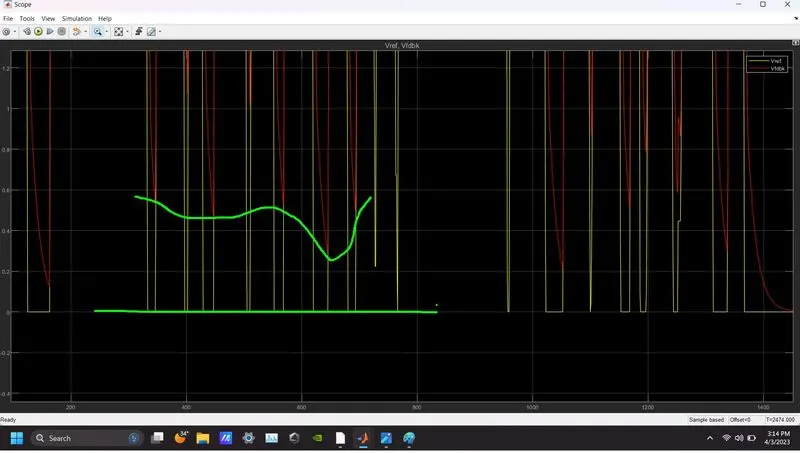
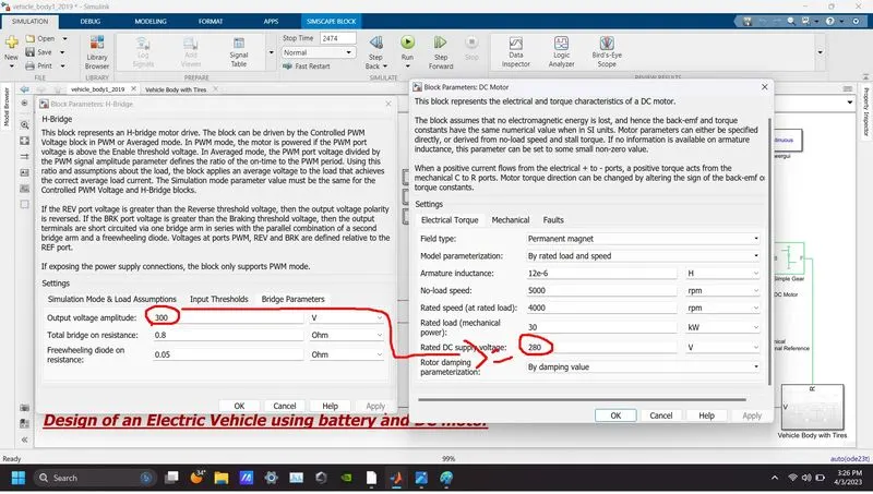
- I have noticed one minor detail which is if you consider the output of the H-bridge and the rating of the DC motor same value like 300VDC then sometimes during the simulation end around 1900sec for FTP75(2474sec) drive cycle so always feeds higher VDC(not much higher) than the rating of the motor as mentioned in the below image.
Pros and cons of EV modeling in Simulink:
Pros:
-
Accurate representation: Simulink provides a flexible environment for modeling EV components, such as batteries, motors, and controllers, which can accurately represent their physical behavior and interactions.
-
Integration with other systems: Simulink can be integrated with other software tools for system-level modeling and simulation, such as MATLAB, Stateflow, and Simscape. This allows for a comprehensive analysis of the EV's performance and behavior.
-
Visualization: Simulink provides powerful visualization tools, such as 2D and 3D plots, that can help users understand the EV's behavior and performance.
-
Rapid prototyping: Simulink enables rapid prototyping of EV models, which can reduce the time and cost of developing new EV technologies.
Cons:
-
Steep learning curve: Simulink can have a steep learning curve.
-
Complex models: EV models in Simulink can become complex and require significant computational resources to run.
-
Cost: Simulink can be expensive, and the cost can increase significantly if additional toolboxes are needed.
-
Maintenance: Maintaining and updating the EV model in Simulink can be time-consuming and require a significant amount of effort.
-
Model limitations: Simulink models can have limitations and may not be able to accurately represent all aspects of the EV's behavior and performance.